EP0147671B1 - Monitoring arrangement in a vehicle brake system provided with an antiskid control system - Google Patents
Monitoring arrangement in a vehicle brake system provided with an antiskid control system Download PDFInfo
- Publication number
- EP0147671B1 EP0147671B1 EP19840114643 EP84114643A EP0147671B1 EP 0147671 B1 EP0147671 B1 EP 0147671B1 EP 19840114643 EP19840114643 EP 19840114643 EP 84114643 A EP84114643 A EP 84114643A EP 0147671 B1 EP0147671 B1 EP 0147671B1
- Authority
- EP
- European Patent Office
- Prior art keywords
- pressure
- switch
- switches
- threshold
- switching
- Prior art date
- Legal status (The legal status is an assumption and is not a legal conclusion. Google has not performed a legal analysis and makes no representation as to the accuracy of the status listed.)
- Expired - Lifetime
Links
Images


Classifications
-
- B—PERFORMING OPERATIONS; TRANSPORTING
- B60—VEHICLES IN GENERAL
- B60T—VEHICLE BRAKE CONTROL SYSTEMS OR PARTS THEREOF; BRAKE CONTROL SYSTEMS OR PARTS THEREOF, IN GENERAL; ARRANGEMENT OF BRAKING ELEMENTS ON VEHICLES IN GENERAL; PORTABLE DEVICES FOR PREVENTING UNWANTED MOVEMENT OF VEHICLES; VEHICLE MODIFICATIONS TO FACILITATE COOLING OF BRAKES
- B60T8/00—Arrangements for adjusting wheel-braking force to meet varying vehicular or ground-surface conditions, e.g. limiting or varying distribution of braking force
- B60T8/32—Arrangements for adjusting wheel-braking force to meet varying vehicular or ground-surface conditions, e.g. limiting or varying distribution of braking force responsive to a speed condition, e.g. acceleration or deceleration
- B60T8/88—Arrangements for adjusting wheel-braking force to meet varying vehicular or ground-surface conditions, e.g. limiting or varying distribution of braking force responsive to a speed condition, e.g. acceleration or deceleration with failure responsive means, i.e. means for detecting and indicating faulty operation of the speed responsive control means
- B60T8/885—Arrangements for adjusting wheel-braking force to meet varying vehicular or ground-surface conditions, e.g. limiting or varying distribution of braking force responsive to a speed condition, e.g. acceleration or deceleration with failure responsive means, i.e. means for detecting and indicating faulty operation of the speed responsive control means using electrical circuitry
-
- B—PERFORMING OPERATIONS; TRANSPORTING
- B60—VEHICLES IN GENERAL
- B60T—VEHICLE BRAKE CONTROL SYSTEMS OR PARTS THEREOF; BRAKE CONTROL SYSTEMS OR PARTS THEREOF, IN GENERAL; ARRANGEMENT OF BRAKING ELEMENTS ON VEHICLES IN GENERAL; PORTABLE DEVICES FOR PREVENTING UNWANTED MOVEMENT OF VEHICLES; VEHICLE MODIFICATIONS TO FACILITATE COOLING OF BRAKES
- B60T8/00—Arrangements for adjusting wheel-braking force to meet varying vehicular or ground-surface conditions, e.g. limiting or varying distribution of braking force
- B60T8/32—Arrangements for adjusting wheel-braking force to meet varying vehicular or ground-surface conditions, e.g. limiting or varying distribution of braking force responsive to a speed condition, e.g. acceleration or deceleration
- B60T8/88—Arrangements for adjusting wheel-braking force to meet varying vehicular or ground-surface conditions, e.g. limiting or varying distribution of braking force responsive to a speed condition, e.g. acceleration or deceleration with failure responsive means, i.e. means for detecting and indicating faulty operation of the speed responsive control means
- B60T8/92—Arrangements for adjusting wheel-braking force to meet varying vehicular or ground-surface conditions, e.g. limiting or varying distribution of braking force responsive to a speed condition, e.g. acceleration or deceleration with failure responsive means, i.e. means for detecting and indicating faulty operation of the speed responsive control means automatically taking corrective action
- B60T8/94—Arrangements for adjusting wheel-braking force to meet varying vehicular or ground-surface conditions, e.g. limiting or varying distribution of braking force responsive to a speed condition, e.g. acceleration or deceleration with failure responsive means, i.e. means for detecting and indicating faulty operation of the speed responsive control means automatically taking corrective action on a fluid pressure regulator
-
- Y—GENERAL TAGGING OF NEW TECHNOLOGICAL DEVELOPMENTS; GENERAL TAGGING OF CROSS-SECTIONAL TECHNOLOGIES SPANNING OVER SEVERAL SECTIONS OF THE IPC; TECHNICAL SUBJECTS COVERED BY FORMER USPC CROSS-REFERENCE ART COLLECTIONS [XRACs] AND DIGESTS
- Y10—TECHNICAL SUBJECTS COVERED BY FORMER USPC
- Y10S—TECHNICAL SUBJECTS COVERED BY FORMER USPC CROSS-REFERENCE ART COLLECTIONS [XRACs] AND DIGESTS
- Y10S303/00—Fluid-pressure and analogous brake systems
- Y10S303/02—Brake control by pressure comparison
- Y10S303/03—Electrical pressure sensor
Definitions
- the invention relates to a monitoring device with the features of the preamble of claim 1.
- Such a braking system including monitoring is known from DE-A1-3237959.
- a warning switch that is designed as a break contact and, for example, warns immediately if a signal line is interrupted and if the pressure to be monitored drops below the threshold.
- the invention has for its object to improve the warning device in order to avoid that in the event of a fault in the warning device, despite falling pressure, a warning or shutdown does not occur.
- the pressure which is applied from the feed valve to the valve device for the anti-lock control can be the pressure of the pressure supply itself, but is preferably the upstream pressure derived from the pressure of the pressure supply by means of a brake control valve, with which the piston or pistons of the master brake cylinder are acted upon.
- the feed valve can disconnect the master brake cylinder from the anti-lock control valves during the anti-lock control or can also switch on the pressure on the valves.
- Fig. 1 shows a brake system that a master cylinder 1, a brake booster 2, a pressure supply 3 and a Control valve 4 for the brake of a wheel 5 contains. For reasons of simplification, only one control channel is shown.
- the arrangement further comprises a pressure switch arrangement 6.
- the switching signals of the pressure switch arrangement 6 reach an electronic control unit 7, a warning lamp 8 and a pump motor 3a.
- the output signals of the control unit 7 activate a feed valve 9 and the control valve 4.
- pressure medium from the hydraulic brake booster 9 is fed to the closed wheel circuit via the feed valve 9 in order to avoid pressure medium being exhausted by being released by means of the control valve 4.
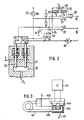
- Fig. 2 shows an embodiment for the safe monitoring of the pressure supply, in particular to avoid that when the pressure drops, the feed valve and the control valves remain actuated and there is a complete loss of pressure.
- FIG. 2 two pressure tappets 20 and 21 are shown, which protrude in a space 22 which is connected to the pressure accumulator 3b of FIG. 1. If the pressure is sufficient, the pressure tappets 20 and 21 are deflected upwards; Contacts S1 and S2 should then assume the switch positions shown.
- the switching thresholds are dimensioned such that when the pressure drops below a first threshold, the contact S2 reaches its central position, whereby the pump motor 3a is switched on and the store is thus reloaded. If, despite this reloading, the pressure continues to drop, the switch S2 moves to position c; in this ground potential is applied to an input of an AND gate 23 and to the input of an inverter 24, so that an OR gate 25 at its receives the middle input signal and delivers a switching signal to terminal 26, via which, for example, the anti-lock control valves and the feed valve are blocked. At the same time, the warning lamp 27 is actuated.
- the AND gate 23 On the other hand, is monitored by means of the AND gate 23 whether the switch S2 is functional. If this is not the case, when the switch S 1 is opened, the other input of the AND gate 23, since the switch position c has not been reached by S 2, still has a signal; the AND gate 23 thereby switches through and sets an error memory via the OR gate 28, which is connected to the terminal 29 and which switches off the control system until the system is serviced.
- the system is intrinsically safe due to this training.
- Timers 30-32 are provided for this. For example, if the motor 3a runs longer than the delay time T 1 of the timer 30, a switching signal is generated which also sets the error memory. This is achieved by means of an inverter 33.
- the timing element 31 is also set by a signal which sets the timing element 30, which then emits a signal immediately and after the input signal has dropped Output signal extended by the time T2.
- the time constant T2 of the timing element 31 is dimensioned such that the output signal of the timing element 31 has ended at a normal starting frequency of the pump before the pump is switched on again. Thus, the timer 32 is reset during normal operation each time the pump is switched on.
- time constant T3 is chosen so that it only delivers an output signal when the pump has been switched on, for example, once or twice in succession at a shorter time interval than in normal operation.
- the time constant is therefore greater than the normal duty cycle of the pump during normal operation plus the usual interval between two start-up phases or twice this sum during normal operation. So that at the output of the series connection of the timing elements 31 and 32, a signal is only generated when the timing element 31 emits a signal which exceeds the time period T3 because of the time constant T2 and the rapid reconnection of the pump.
- FIGS. 3 and 4 avoids this disadvantage.
- the circuit is based on a redundant pressure measurement using a Bourdon tube and Hall elements.
- the switching thresholds are implemented using comparators.
- Fig. 3 shows the measurement in principle.
- the Connecting part 41 connected to the pressure line and its lower tube part is deflected more or less according to arrow 42 in the case of pressure variation. This also varies the distance between magnets 43a and b connected to the tube and Hall sensors 44a and b and thus also their output signals. These signals are fed to an evaluation circuit 45.
- Each sensor 44a and b is connected to two threshold switches 46a and b or 47a and b, which emit an output signal when certain signal quantities are reached.
- the switching thresholds of the threshold switches are set so that e.g. the threshold switches 46a and 47a (also taking tolerances into account), below a limit of e.g. 100 bar (storage precharge pressure) and the threshold switches 46b and 47b below a lower limit of e.g. Give a signal 90 bar.
- a warning lamp 48 is activated and the power supply of a relay 52 is blocked via OR gates 49 and / or 50 and by means of the AND gate 51.
- a signal is given on line 57 via AND gates 55, 56, which leads to a shutdown of the ABS system.
- the power supply to the ABS valves is interrupted and pressure consumption is prevented redundantly until sufficient pressure has built up again.
- the threshold value transmitters 46b and 47b are used to monitor whether the threshold value switches 46a and 47a are functional. This is done using AND gates 53 and 54, in which the following connections are made:
- valve relay 52 If one of the AND gates 53 or 54 emits an error signal on the basis of such a signal combination, the valve relay 52 is again switched off via one of the OR gates 49 and 50. At the same time, however, AND gates 55 and 56 are blocked. The signal at terminal 57 thus disappears, which is evaluated as a system error when relay 52 is switched off. This locks the ABS system until external intervention (maintenance) and a fault memory is possibly set.
Abstract
Description
Die Erfindung betrifft eine Überwachungseinrichtung mit den Merkmalen des Oberbegriffs des Anspruchs 1.The invention relates to a monitoring device with the features of the preamble of claim 1.
Aus der DE-A1-3237959 ist ein derartiges Bremssystem samt Überwachung bekannt. Dort ist ein Warnschalter vorgesehen, der als Öffner ausgebildet ist und z.B. sofort warnt, wenn ein Signalleitung unterbrochen wird und wenn der zu überwachende Druck unter die Schwelle absinkt.Such a braking system including monitoring is known from DE-A1-3237959. There is a warning switch that is designed as a break contact and, for example, warns immediately if a signal line is interrupted and if the pressure to be monitored drops below the threshold.
Der Erfindung liegt die Aufgabe zugrunde die Warneinrichtung zu verbessern, um zu vermeiden, daß bei einer Störung in der Warneinrichtung trotz absinkenden Drucks eine Warnung oder Abschaltung nicht zustande kommt.The invention has for its object to improve the warning device in order to avoid that in the event of a fault in the warning device, despite falling pressure, a warning or shutdown does not occur.
Diese Aufgabe wird durch die Merkmale des Anspruchs 1 gelöst.This object is solved by the features of claim 1.
Weitere Verbesserungen und Ausgestaltungen ergeben sich aus den Unteransprüchen und der Figurenbeschreibung.Further improvements and refinements result from the subclaims and the description of the figures.
Der Druck, der vom Einspeiseventil an die Ventileinrichtung für die Antiblockierregelung gelegt wird, kann der Druck der Druckversorgung selbst sein, ist aber vorzugsweise der mittels eines Bremssteuerventils vom Druck der Druckversorgung abgeleitete Vordruck mit dem der oder die Kolben des Hauptbremszylinders beaufschlagt werden. Das Einspeiseventil kann dabei den Hauptbremszylinder während der Antiblockierregelung von den Antiblockierregelventilen abtrennen oder aber auch den Druck zusätzlich an die Ventile anschalten.The pressure which is applied from the feed valve to the valve device for the anti-lock control can be the pressure of the pressure supply itself, but is preferably the upstream pressure derived from the pressure of the pressure supply by means of a brake control valve, with which the piston or pistons of the master brake cylinder are acted upon. The feed valve can disconnect the master brake cylinder from the anti-lock control valves during the anti-lock control or can also switch on the pressure on the valves.
Anhand der Zeichnungen werden Ausführungsbeispiele der Erfindung näher erläutert. Es zeigen:
- Fig. 1
- ein Bremssystem, bei dem die Erfindung angewendet ist,
- Fig. 2
- eine erste detaillierte Überwachungseinrichtung,
- Fig. 3
- Druckmeßanordnung,
- Fig. 4
- eine zweite detaillierte Überwachungseinrichtung.
- Fig. 1
- a braking system to which the invention is applied,
- Fig. 2
- a first detailed monitoring device,
- Fig. 3
- Pressure measuring arrangement,
- Fig. 4
- a second detailed monitoring device.
Fig. 1 zeigt ein Bremssystem, das einen Hauptbremszylinder 1, einen Bremskraftverstärker 2, eine Druckversorgung 3 und ein Regelventil 4 für die Bremse eines Rads 5 enthält. Aus Gründen der Vereinfachung ist nur ein Regelkanal dargestellt. Die Anordnung umfaßt weiterhin eine Druckschalteranordnung 6. Die Schaltsignale der Druckschalteranordnung 6 gelangen zu einem elektronischen Steuergerät 7, zu einer Warnlampe 8 und zu einem Pumpenmotor 3a. Die Ausgagssignale des Steuergerätes 7 aktivieren ein Einspeiseventil 9 und das Regelventil 4.Fig. 1 shows a brake system that a master cylinder 1, a brake booster 2, a pressure supply 3 and a Control valve 4 for the brake of a wheel 5 contains. For reasons of simplification, only one control channel is shown. The arrangement further comprises a
Im vorliegenden Beispiel wird während der Antiblockierregelung über das Einspeiseventil 9 Druckmittel aus dem hydraulischen Bremskraftverstärker dem geschlossenen Radkreis zugeführt, um ein Erschöpfen von Druckmittel durch das Auslassen mittels des Regelventils 4 zu vermeiden.In the present example, during the anti-lock control, pressure medium from the
Fig. 2 zeigt ein Ausführungsbeispiel zur sicheren Überwachung der Druckversorgung, um insbesondere zu vermeiden, daß bei Druckabfall das Einspeiseventil und die Regelventile betätigt bleiben und es dadurch zu völligem Druckausfall kommt.Fig. 2 shows an embodiment for the safe monitoring of the pressure supply, in particular to avoid that when the pressure drops, the feed valve and the control valves remain actuated and there is a complete loss of pressure.
In Fig. 2 sind zwei Druckstößel 20 und 21 gezeigt, die in einem Raum 22 ragen, der mit dem Druckspeicher 3b der Fig. 1 verbunden ist. Bei einem ausreichenden Druck sind die Druckstößel 20 und 21 nach oben ausgelenkt; Kontakte S₁ und S₂ sollen dann die dargestellten Schaltstellungen einnehmen.In Fig. 2, two
Die Schaltschwellen sind so bemessen, daß bei Absinken des Drucks unter eine erste Schwelle der Kontakt S₂ in seine Mittelstellung gelangt, wodurch der Pumpenmotor 3a eingeschaltet und damit der Speicher nachgeladen wird. Sinkt trotz dieses Nachladens der Druck weiter ab, so gelangt der Schalter S₂ in die Stellung c; in dieser wird Massepotential an einen Eingang eines Und-Gatters 23 und an den Eingang eines Inverters 24 gelegt, so daß ein Oder-Gatter 25 an seinem mittleren Eingang Signal erhält und ein Schaltsignal an die Klemme 26 liefert, über die z.B. die Antiblockierregelventile und das Einspeiseventil gesperrt werden. Gleichzeitig wird die Warnlampe 27 betätigt.The switching thresholds are dimensioned such that when the pressure drops below a first threshold, the contact S₂ reaches its central position, whereby the
Sinkt der Druck im Speicher noch weiter ab, so öffnet der Schalter S₁ und läßt damit Signale an den Eingängen der Gatter 23 und 25 entstehen. Hat wegen eines Fehlers der Schalter S₂ die Abschaltung über das Oder-Gatter 25 noch nicht bewirkt, so wird durch dieses Öffnen nun die Abschaltung nachgeholt. Es ist also eine redundante Überwachung der Druckhöhe vorhanden.If the pressure in the memory drops even further, the switch S 1 opens, thus giving rise to signals at the inputs of the
Andererseits wird mittels des Und-Gatters 23 überwacht, ob der Schalter S₂ funktionsfähig ist. Ist dies nicht der Fall, so weist bei Öffnen des Schalters S₁ der andere Eingang des Und-Gatters 23, da die Schalterstellung c durch S₂ nicht erreicht ist, noch Signal; damit schaltet das Und-Gatter 23 durch und setzt über das Oder-Gatter 28 einen Fehlerspeicher, der an der Klemme 29 angeschlossen ist und der die Regelung bis zu einer Wartung der Anlage abschaltet.On the other hand, is monitored by means of the
Die Anlage ist aufgrund dieser Ausbildung eigensicher.The system is intrinsically safe due to this training.
Zusätzlich wird hier noch überwacht, ob der Pumpenmotor 3a zu häufig und zu lange angeschaltet wird. Hierzu sind Zeitglieder 30-32 vorgesehen. Läuft z.B. der Motor 3a länger als durch die Verzögerungszeit T₁ des Zeitglieds 30 vorgegeben, so wird ein Schaltsignal erzeugt, das ebenfalls der Fehlerspeicher setzt. Dies wird mittels eines Inverters 33 erreicht. Andererseits wird durch ein das Zeitglied 30 setzendes Signal auch das Zeitglied 31 gesetzt, das dann sofort ein Signal abgibt und nach Abfall des Eingangssignals sein Ausgangssignal um die Zeit T₂ verlängert. Die Zeitkonstante T₂ des Zeitglieds 31 ist so bemessen, daß bei normaler Einschaltfrequenz der Pumpe das Ausgangssignal des Zeitglieds 31 beendet ist, bevor die Pumpe erneut eingeschaltet wird. Damit wird das Zeitglied 32 bei Normalbetrieb jeweils bei Pumpeneinschaltung neu gesetzt. Seine Zeitkonstante T₃ ist so gewählt, daß es erst ein Ausgangssignal liefert, wenn die Pumpe z.B. ein- oder zweimal hintereinander in kürzerem Zeitabstand als bei Normalbetrieb angeschaltet wurde. Die Zeitkonstante ist also größer als die bei Normalbetrieb übliche Einschaltdauer der Pumpe plus dem bei Normalbetrieb üblichem Abstand zwischen zwei Einschaltphasen bzw, dem Zweifachen dieser Summe. Damit wird am Ausgang der Reihenschaltung der Zeitglieder 31 und 32 ein Signal nur erzeugt, wenn das Zeitglied 31 ein Signal abgibt, das wegen der Zeitkonstante T₂ und der zu schnellen Wiederanschaltung der Pumpe die Zeitdauer T₃ übersteigt.In addition, it is also monitored here whether the
Die Überwachungsschaltung der Fig. 2 läßt sich durch Einkoppeln von Signalen über die Verstärker 34 und 35 jederzeit überprüfen.2 can be checked at any time by coupling signals via the
Die Plausibilitätsprüfung an Und Gatter 23 der Fig. 2 setzt voraus, daß sich die Toleranzbänder der Überwachungsschwellen S1 und S2c nicht überlappen, so daß bei Ansprechen von S1, S2 c bereits sicher geschaltet hat, was zu Toleranzproblemen führen kann, da sich die Abschaltschwellen aus Sicherheitsgründen oberhalb des Speichervorladedrucks befinden müssen.The plausibility check on and
Das weitere Ausführungsbeispiel der Fig. 3 und 4 vermeidet diesen Nachteil. Die Schaltung basiert auf einer redundanten Druckmessung mittels Bourdon-Rohr und Hall-Elemente. Die Schaltschwellen sind mittels Komparatoren realisiert.The further embodiment of FIGS. 3 and 4 avoids this disadvantage. The circuit is based on a redundant pressure measurement using a Bourdon tube and Hall elements. The switching thresholds are implemented using comparators.
Fig. 3 zeigt die Messung im Prinzip. Mit 40 ist der als Bourdon-Rohr ausgebildete Druckmesser bezeichnet, der am Anschlußteil 41 an die Druckleitung angeschlossenen und dessen unteres Rohrteil bei Druckvariation entsprechend dem Pfeil 42 mehr oder weniger weit ausgelenkt wird. Damit wird auch der Abstand zwischen mit dem Rohr verbundenen Magneten 43a und b und Hall-Sensoren 44a und b variiert und damit auch deren Ausgangssignale. Diese Signale werden einer Auswerteschaltung 45 zugeführt.Fig. 3 shows the measurement in principle. With 40 is designed as a Bourdon tube pressure meter, the
Diese ist zusammen mit den Hall-Sensoren 44a und b in Fig. 4 dargestellt. Jeder Sensor 44a und b ist mit zwei Schwellwertschaltern 46a und b bzw. 47a und b verbunden, die bei Erreichen bestimmter Signalgrößen ein Ausgangssignal abgeben. Die Schaltschwellen der Schwellwertschalter sind so gelegt, daß z.B. die Schwellwertschalter 46a und 47a (auch unter Berücksichtigung von Toleranzen), unterhalb eines Grenzwertes von z.B. 100 bar (Speichervorladedruck) und die Schwellwertschalter 46b und 47b unterhalb eines niedrigeren Grenzwertes von z.B. 90 bar ein Signal abgeben.This is shown together with the Hall sensors 44a and b in FIG. 4. Each sensor 44a and b is connected to two
Gibt einer oder beide Grenzwertschalter ein Signal ab, so wird eine Warnlampe 48 angesteuert und über Oder-Gatter 49 und/oder 50 und mittels des Und-Gatters 51 die Stromversorgung eines Relais 52 gesperrt. Gleichzeitig wird über Und-Gatter 55, 56 ein Signal auf Leitung 57 gegeben, was zu einer Abschaltung des ABS-Systems führt. Hierdurch wird die Stromversorgung der ABS-Ventile unterbrochen und damit Druckverbrauch redundant unterbunden, bis sich wieder ein ausreichender Druck aufgebaut hat.If one or both limit switches give a signal, a warning
Mit den Schwellwertgebern 46b und 47b wird überwacht, ob die Schwellwertschalter 46a und 47a funktionsfähig sind. Dies geschieht mittels Und-Gatter 53 und 54, in denen folgende Verknüpfungen vorgenommen werden:
Gibt eines der Und-Gatter 53 oder 54 aufgrund einer solchen Signalkombination ein Fehlersignal ab, so wird wieder über eines der Oder-Gatter 49 und 50 eine Abschaltung des Ventilrelais 52 ausgelöst. Gleichzeitig werden jedoch Und-Gatter 55 und 56 gesperrt. Damit verschwindet das Signal an Klemme 57, was bei abgeschaltetem Relais 52 als Systemfehler gewertet wird. Damit wird das ABS-System bis zu einem Eingriff von außen (Wartung) gesperrt und eventuell ein Fehlerspeicher gesetzt.If one of the AND
Claims (11)
- Monitoring arrangement for a pressure supply (3) comprising a pump (3a) and hydraulic accumulator (3b) in a vehicle brake system (1, 2, 5) which is provided with an anti-skid control system and has at least one closed brake circuit into which at least one valve arrangement (4), actuated in the event of a tendency to lock up, is inserted for the purpose of varying the brake pressure, the pressure of the pressure supply or a pressure derived therefrom being fed to the valve arrangement (4) during the anti-skid control by means of a feed valve (9), and the monitoring device containing a pressure-switch arrangement (6) which is assigned to the pressure supply (3) and, when the pressure falls below a predetermined pressure threshold, produces a warning signal (at 8) and/or switching signal for switching off the pressure feed (9) and the valve arrangement (4), characterised in that the pressure-switch arrangement (6) has two switches (S₁, S₂; 43a 44a, 43b 44b) actuable at different pressure levels and in that the interconnection of the pressure switches (S₁, S₂; 43, 44) is such that a first warning and/or switching signal is produced when the upper threshold is undershot and a second warning and/or switching signal is produced when the pressure switch (S₁) with the lower threshold responds without the pressure switch (S₂) with the higher switching threshold having responded.
- Monitoring device according to Claim 1, characterised in that the pressure-switch arrangement (6) has two switching tappets, which are exposed to the pressure of the pressure supply (3) and to which switches (S₁, S₂) actuated by them are assigned.
- Monitoring arrangement according to Claim 1, characterised in that a Bourdon tube (40) is provided for the purpose of pressure measurement and in that two switches (43 and 44) are operative between the fixed and the movable part of this tube.
- Monitoring arrangement according to one of Claims 1-3, characterised in that the switches (43, 44) are designed as proximity switches, in particular Hall-effect sensors.
- Monitoring device according to Claim 2, characterised in that one of the switches (S₁ or S₂) to be actuated opens when the associated threshold is undershot and the other closes.
- Monitoring arrangement according to one of Claims 1-5, characterised in that two switching thresholds (46a and 47a and b respectively) are assigned to each switch.
- Monitoring arrangement according to Claim 6, characterised in that the second switching signal is produced when one of the switches responds with its lower pressure threshold (46b or 47b) without the other switch having responded with its higher pressure threshold.
- Monitoring arrangement according to one of Claims 1-7, characterised in that the first switching signal puts the anti-skid control system out of operation for the duration of its presence but that the second switching signal switches off the anti-skid control system permanently.
- Monitoring arrangement according to Claim 6, characterised in that the signal produced at the low switching threshold (46b or 47b) of a switch (44a, 44b) is in each case compared with the signal of the higher switching threshold (47a or 46a) of the other switch (44a, 44b).
- Monitoring arrangement according to one of Claims 1-9, characterised in that the pump motor (3a) is assigned a timing element (39) which produces a switching signal if the pump motor (3a) is switched on for longer than a predetermined time (T₁).
- Monitoring arrangement according to one of Claims 1-10, characterised in that the pump motor is assigned a combination of timing elements (31 and 32) which produces a switching signal after a time T₃ if the pump motor (3a) has been switched on again one or more times after the end of an ON period before the expiry of a predetermined time T₂.
Priority Applications (1)
| Application Number | Priority Date | Filing Date | Title |
|---|---|---|---|
| AT84114643T ATE65058T1 (en) | 1983-12-07 | 1984-12-01 | MONITORING DEVICE IN A VEHICLE BRAKING SYSTEM EQUIPPED WITH AN ANTI-LOCK CONTROL SYSTEM. |
Applications Claiming Priority (2)
| Application Number | Priority Date | Filing Date | Title |
|---|---|---|---|
| DE3344183 | 1983-12-07 | ||
| DE3344183 | 1983-12-07 |
Publications (3)
| Publication Number | Publication Date |
|---|---|
| EP0147671A2 EP0147671A2 (en) | 1985-07-10 |
| EP0147671A3 EP0147671A3 (en) | 1988-01-13 |
| EP0147671B1 true EP0147671B1 (en) | 1991-07-10 |
Family
ID=6216226
Family Applications (1)
| Application Number | Title | Priority Date | Filing Date |
|---|---|---|---|
| EP19840114643 Expired - Lifetime EP0147671B1 (en) | 1983-12-07 | 1984-12-01 | Monitoring arrangement in a vehicle brake system provided with an antiskid control system |
Country Status (4)
| Country | Link |
|---|---|
| US (1) | US4753492A (en) |
| EP (1) | EP0147671B1 (en) |
| JP (1) | JPS60139560A (en) |
| AT (1) | ATE65058T1 (en) |
Families Citing this family (14)
| Publication number | Priority date | Publication date | Assignee | Title |
|---|---|---|---|---|
| DE3538120A1 (en) * | 1985-10-26 | 1987-04-30 | Teves Gmbh Alfred | PRESSURE SUPPLY SYSTEM, ESPECIALLY FOR MOTOR VEHICLE BRAKE SYSTEMS |
| DE3636263A1 (en) * | 1986-10-24 | 1988-04-28 | Teves Gmbh Alfred | ELECTRICAL SWITCHING DEVICE |
| DE3729787A1 (en) * | 1987-04-01 | 1988-10-13 | Teves Gmbh Alfred | BLOCK-PROTECTED HYDRAULIC BRAKE SYSTEM FOR MOTOR VEHICLES |
| JP2677377B2 (en) * | 1987-08-30 | 1997-11-17 | 株式会社デンソー | Pressure control device for accumulator for braking device |
| JPS6490861A (en) * | 1987-09-30 | 1989-04-07 | Sumitomo Electric Industries | Tester for liquid pressure circuit of anti-lock control system |
| GB2245038B (en) * | 1990-06-07 | 1994-03-23 | Toyota Motor Co Ltd | Device for detecting accumulator fluid leakage through control valve and restoring proper valve seating |
| JP2762171B2 (en) * | 1991-01-09 | 1998-06-04 | 本田技研工業株式会社 | Pressure source for pressure equipment |
| GB9315895D0 (en) * | 1993-07-31 | 1993-09-15 | Lucas Ind Plc | Anti-lock braking system |
| JP3473209B2 (en) * | 1995-08-31 | 2003-12-02 | アイシン精機株式会社 | Pressure device |
| DE19807368A1 (en) * | 1998-02-21 | 1999-08-26 | Bosch Gmbh Robert | Method and device for controlling a brake system |
| US6119059A (en) * | 1998-03-26 | 2000-09-12 | Institute Of Occupational Safety And Health, Council Of Labor Affairs, Executive Yuan | Advanced warning device for monitoring the working conditions of hydraulic brakes system of motor vehicles |
| DE19828552C1 (en) * | 1998-06-26 | 2000-02-03 | Bosch Gmbh Robert | Pump control method for automobile electrohydraulic braking system |
| JP4588578B2 (en) * | 2004-12-16 | 2010-12-01 | 本田技研工業株式会社 | Brake device for vehicle |
| US9173342B2 (en) | 2012-09-06 | 2015-11-03 | Cnh Industrial America Llc | Storage tank sump arrangement for an agricultural implement |
Family Cites Families (21)
| Publication number | Priority date | Publication date | Assignee | Title |
|---|---|---|---|---|
| US2935875A (en) * | 1954-11-15 | 1960-05-10 | Licentia Gmbh | Device for electrically tele-transmitting the measured value of pressure indicators |
| US2947579A (en) * | 1957-04-17 | 1960-08-02 | Cook Electric Co | Antiskid device |
| US3180152A (en) * | 1962-02-09 | 1965-04-27 | Micro Metrics Sales Corp | Pressure transducer |
| FR1359829A (en) * | 1963-03-19 | 1964-04-30 | Further training in hydraulic braking signaling installations on motor vehicles | |
| US3251032A (en) * | 1963-08-13 | 1966-05-10 | Lawrence R Brayton | Brake failure warning device |
| DE1555132A1 (en) * | 1966-07-30 | 1970-07-30 | Daimler Benz Ag | Warning device for malfunctions on hydraulically or pneumatically actuated brakes of vehicles, in particular of motor vehicles |
| US3402972A (en) * | 1966-08-11 | 1968-09-24 | Gen Electric | Continuous pressure control system |
| US3529288A (en) * | 1967-01-10 | 1970-09-15 | Berg Mfg & Sales Co | Brake system safety indicator |
| DE2345860A1 (en) * | 1970-09-23 | 1975-03-27 | Teldix Gmbh | Hydraulic brake system with leak detector - monitors reservoir fluid level and pressure and shuts off respective brakes |
| DE2232832A1 (en) * | 1971-07-20 | 1973-02-01 | Fiat Spa | PROTECTIVE DEVICE FOR HYDRAULIC CIRCUITS |
| DE2249956C2 (en) * | 1972-10-12 | 1984-06-20 | Robert Bosch Gmbh, 7000 Stuttgart | Hydraulic storage unit for two separate supply circuits |
| DE2342307C2 (en) * | 1973-08-22 | 1984-12-20 | Robert Bosch Gmbh, 7000 Stuttgart | Arrangement for checking an anti-lock control system for vehicle brake systems |
| DE2360139A1 (en) * | 1973-12-03 | 1975-06-05 | Teldix Gmbh | Pressurised fluid supply system for motor vehicle - has central pump and valve kept open by given pressure level |
| US3963375A (en) * | 1974-03-12 | 1976-06-15 | Curtis George C | Time delayed shut-down circuit for recirculation pump |
| NO150656C (en) * | 1978-05-18 | 1984-11-28 | Oerlikon Buehrle Ag | DEVICE FOR MONITORING OF SLIDE PROTECTION TO A VEHICLE |
| DE2822143A1 (en) * | 1978-05-20 | 1979-11-22 | Bosch Gmbh Robert | ANTI-LOCK CONTROL SYSTEM |
| DE3237959A1 (en) * | 1981-11-14 | 1983-05-26 | Robert Bosch Gmbh, 7000 Stuttgart | Hydraulic dual circuit servo brake device |
| DE3232051A1 (en) * | 1982-08-28 | 1984-03-01 | Alfred Teves Gmbh, 6000 Frankfurt | METHOD FOR MONITORING AND CONTROLLING EXTERNAL ENERGY-SUPPLIED HYDRAULIC BRAKE-SLIP CONTROL SYSTEMS AND DEVICE FOR IMPLEMENTING THE METHOD |
| DE3421787A1 (en) * | 1983-06-14 | 1985-01-24 | Robert Bosch Gmbh, 7000 Stuttgart | Antilock control system |
| DE3421756A1 (en) * | 1983-06-14 | 1985-01-03 | Robert Bosch Gmbh, 7000 Stuttgart | Antilock control system |
| DE3418042A1 (en) * | 1984-05-15 | 1985-11-21 | Alfred Teves Gmbh, 6000 Frankfurt | DEVICE FOR MONITORING THE AUXILIARY ENERGY PRESSURE OF A SLIP-CONTROLLED BRAKE SYSTEM |
-
1984
- 1984-12-01 EP EP19840114643 patent/EP0147671B1/en not_active Expired - Lifetime
- 1984-12-01 AT AT84114643T patent/ATE65058T1/en not_active IP Right Cessation
- 1984-12-06 JP JP59256617A patent/JPS60139560A/en active Pending
-
1987
- 1987-04-27 US US07/049,034 patent/US4753492A/en not_active Expired - Fee Related
Also Published As
| Publication number | Publication date |
|---|---|
| ATE65058T1 (en) | 1991-07-15 |
| EP0147671A3 (en) | 1988-01-13 |
| JPS60139560A (en) | 1985-07-24 |
| US4753492A (en) | 1988-06-28 |
| EP0147671A2 (en) | 1985-07-10 |
Similar Documents
| Publication | Publication Date | Title |
|---|---|---|
| DE3418042C2 (en) | ||
| EP0147671B1 (en) | Monitoring arrangement in a vehicle brake system provided with an antiskid control system | |
| EP0979189B1 (en) | Circuit configuration for a motor vehicle control system | |
| DE2251472C3 (en) | Circuit arrangement for controlling the mechanical movement of a solenoid valve armature | |
| EP1966016B1 (en) | Pushbutton for actuating an electropneumatic parking brake (eph) | |
| DE2726465A1 (en) | CENTRAL CONTROL FOR VEHICLES | |
| DE3924988C2 (en) | Circuit arrangement for controlling the safety relay of an electronically controlled brake system of a motor vehicle | |
| DE3630342C2 (en) | Method for monitoring an anti-lock brake system | |
| DE3102227C2 (en) | ||
| DE3502451A1 (en) | BRAKE SYSTEM WITH SLIP CONTROL | |
| EP0082916A2 (en) | Installation d'antiblocage | |
| DE3137200A1 (en) | TWO-CIRCUIT BRAKING DEVICE | |
| DE1655460A1 (en) | Anti-lock control system for hydraulic brakes | |
| DE2813058C2 (en) | Tire pressure monitoring device | |
| EP0111672B1 (en) | Hydraulic vehicle brake system | |
| DE3835642C2 (en) | Circuit arrangement for monitoring a hydraulic motor vehicle brake system with an anti-lock device | |
| EP0284718B1 (en) | Anti-locking hydraulic-brake arrangement for motor vehicles | |
| EP0738640A2 (en) | Compressed air brake system for a commercial vehicle | |
| DE3418043C2 (en) | Anti-lock brake system for motor vehicles | |
| DE2345860A1 (en) | Hydraulic brake system with leak detector - monitors reservoir fluid level and pressure and shuts off respective brakes | |
| EP0535392A2 (en) | Diagnostic method for an electronically controlled fluid pressure brake installation of a vehicle | |
| DE3443880A1 (en) | Monitoring device in a vehicle brake system provided with an antilock control system | |
| DE2723847A1 (en) | Antiskid brake control system - has failsafe interlock which monitors relative pressures on wheels of each axle and regulates inhibit control | |
| DD299629A5 (en) | CIRCUIT ARRANGEMENT FOR TRANSMITTING THE END LEVELS OF A VARIETY OF VALVES | |
| DE4309243A1 (en) | Brake system with electronic control of the brake force distribution |
Legal Events
| Date | Code | Title | Description |
|---|---|---|---|
| PUAI | Public reference made under article 153(3) epc to a published international application that has entered the european phase |
Free format text: ORIGINAL CODE: 0009012 |
|
| AK | Designated contracting states |
Designated state(s): AT FR GB IT SE |
|
| RTI1 | Title (correction) | ||
| PUAL | Search report despatched |
Free format text: ORIGINAL CODE: 0009013 |
|
| AK | Designated contracting states |
Kind code of ref document: A3 Designated state(s): AT FR GB IT SE |
|
| 17P | Request for examination filed |
Effective date: 19880606 |
|
| 17Q | First examination report despatched |
Effective date: 19900206 |
|
| GRAA | (expected) grant |
Free format text: ORIGINAL CODE: 0009210 |
|
| AK | Designated contracting states |
Kind code of ref document: B1 Designated state(s): AT FR GB IT SE |
|
| REF | Corresponds to: |
Ref document number: 65058 Country of ref document: AT Date of ref document: 19910715 Kind code of ref document: T |
|
| ET | Fr: translation filed | ||
| GBT | Gb: translation of ep patent filed (gb section 77(6)(a)/1977) | ||
| ITF | It: translation for a ep patent filed |
Owner name: STUDIO JAUMANN |
|
| PGFP | Annual fee paid to national office [announced via postgrant information from national office to epo] |
Ref country code: SE Payment date: 19911106 Year of fee payment: 8 |
|
| PGFP | Annual fee paid to national office [announced via postgrant information from national office to epo] |
Ref country code: GB Payment date: 19911122 Year of fee payment: 8 |
|
| PGFP | Annual fee paid to national office [announced via postgrant information from national office to epo] |
Ref country code: AT Payment date: 19911125 Year of fee payment: 8 |
|
| PGFP | Annual fee paid to national office [announced via postgrant information from national office to epo] |
Ref country code: FR Payment date: 19911230 Year of fee payment: 8 |
|
| RAP4 | Party data changed (patent owner data changed or rights of a patent transferred) |
Owner name: ROBERT BOSCH GMBH |
|
| PLBE | No opposition filed within time limit |
Free format text: ORIGINAL CODE: 0009261 |
|
| STAA | Information on the status of an ep patent application or granted ep patent |
Free format text: STATUS: NO OPPOSITION FILED WITHIN TIME LIMIT |
|
| 26N | No opposition filed | ||
| PG25 | Lapsed in a contracting state [announced via postgrant information from national office to epo] |
Ref country code: GB Effective date: 19921201 Ref country code: AT Effective date: 19921201 |
|
| PG25 | Lapsed in a contracting state [announced via postgrant information from national office to epo] |
Ref country code: SE Effective date: 19921202 |
|
| GBPC | Gb: european patent ceased through non-payment of renewal fee |
Effective date: 19921201 |
|
| PG25 | Lapsed in a contracting state [announced via postgrant information from national office to epo] |
Ref country code: FR Effective date: 19930831 |
|
| REG | Reference to a national code |
Ref country code: FR Ref legal event code: ST |
|
| EUG | Se: european patent has lapsed |
Ref document number: 84114643.4 Effective date: 19930709 |