EP0146914A2 - Electromotoric drive for adjusting the head and foot support of lying furniture - Google Patents
Electromotoric drive for adjusting the head and foot support of lying furniture Download PDFInfo
- Publication number
- EP0146914A2 EP0146914A2 EP84115781A EP84115781A EP0146914A2 EP 0146914 A2 EP0146914 A2 EP 0146914A2 EP 84115781 A EP84115781 A EP 84115781A EP 84115781 A EP84115781 A EP 84115781A EP 0146914 A2 EP0146914 A2 EP 0146914A2
- Authority
- EP
- European Patent Office
- Prior art keywords
- drive
- spindle
- electric motor
- sleeve
- threaded spindle
- Prior art date
- Legal status (The legal status is an assumption and is not a legal conclusion. Google has not performed a legal analysis and makes no representation as to the accuracy of the status listed.)
- Granted
Links
Images


Classifications
-
- F—MECHANICAL ENGINEERING; LIGHTING; HEATING; WEAPONS; BLASTING
- F16—ENGINEERING ELEMENTS AND UNITS; GENERAL MEASURES FOR PRODUCING AND MAINTAINING EFFECTIVE FUNCTIONING OF MACHINES OR INSTALLATIONS; THERMAL INSULATION IN GENERAL
- F16H—GEARING
- F16H25/00—Gearings comprising primarily only cams, cam-followers and screw-and-nut mechanisms
- F16H25/18—Gearings comprising primarily only cams, cam-followers and screw-and-nut mechanisms for conveying or interconverting oscillating or reciprocating motions
- F16H25/20—Screw mechanisms
- F16H25/2021—Screw mechanisms with means for avoiding overloading
-
- A—HUMAN NECESSITIES
- A47—FURNITURE; DOMESTIC ARTICLES OR APPLIANCES; COFFEE MILLS; SPICE MILLS; SUCTION CLEANERS IN GENERAL
- A47C—CHAIRS; SOFAS; BEDS
- A47C20/00—Head -, foot -, or like rests for beds, sofas or the like
- A47C20/04—Head -, foot -, or like rests for beds, sofas or the like with adjustable inclination
- A47C20/041—Head -, foot -, or like rests for beds, sofas or the like with adjustable inclination by electric motors
-
- F—MECHANICAL ENGINEERING; LIGHTING; HEATING; WEAPONS; BLASTING
- F16—ENGINEERING ELEMENTS AND UNITS; GENERAL MEASURES FOR PRODUCING AND MAINTAINING EFFECTIVE FUNCTIONING OF MACHINES OR INSTALLATIONS; THERMAL INSULATION IN GENERAL
- F16H—GEARING
- F16H25/00—Gearings comprising primarily only cams, cam-followers and screw-and-nut mechanisms
- F16H25/18—Gearings comprising primarily only cams, cam-followers and screw-and-nut mechanisms for conveying or interconverting oscillating or reciprocating motions
- F16H25/20—Screw mechanisms
- F16H2025/2062—Arrangements for driving the actuator
- F16H2025/2071—Disconnecting drive source from the actuator, e.g. using clutches for release of drive connection during manual control
-
- F—MECHANICAL ENGINEERING; LIGHTING; HEATING; WEAPONS; BLASTING
- F16—ENGINEERING ELEMENTS AND UNITS; GENERAL MEASURES FOR PRODUCING AND MAINTAINING EFFECTIVE FUNCTIONING OF MACHINES OR INSTALLATIONS; THERMAL INSULATION IN GENERAL
- F16H—GEARING
- F16H25/00—Gearings comprising primarily only cams, cam-followers and screw-and-nut mechanisms
- F16H25/18—Gearings comprising primarily only cams, cam-followers and screw-and-nut mechanisms for conveying or interconverting oscillating or reciprocating motions
- F16H25/20—Screw mechanisms
- F16H2025/2062—Arrangements for driving the actuator
- F16H2025/2084—Perpendicular arrangement of drive motor to screw axis
-
- F—MECHANICAL ENGINEERING; LIGHTING; HEATING; WEAPONS; BLASTING
- F16—ENGINEERING ELEMENTS AND UNITS; GENERAL MEASURES FOR PRODUCING AND MAINTAINING EFFECTIVE FUNCTIONING OF MACHINES OR INSTALLATIONS; THERMAL INSULATION IN GENERAL
- F16H—GEARING
- F16H25/00—Gearings comprising primarily only cams, cam-followers and screw-and-nut mechanisms
- F16H25/18—Gearings comprising primarily only cams, cam-followers and screw-and-nut mechanisms for conveying or interconverting oscillating or reciprocating motions
- F16H25/20—Screw mechanisms
- F16H2025/2062—Arrangements for driving the actuator
- F16H2025/209—Arrangements for driving the actuator using worm gears
Definitions
- the present invention relates to an electric motor drive for adjusting the head or foot wedge of a piece of reclining furniture, which drive has an electric motor which drives a worm wheel via a worm, which in turn is drive-connected to a threaded spindle which engages in a push tube in such a way that a rotational movement of the electric motor is converted into a linear movement of the push tube.
- a so-called linear drive is usually used for the electromotive adjustment of a head or foot wedge of a piece of reclining furniture.
- This has a push and pull motor which is fixedly connected to the reclining furniture frame and has a linearly displaceable rod which is usually connected to the part to be adjusted via a linkage.
- the adjustment movement is controlled via manually operated control elements.
- In the known drives there is a positive connection between the part to be adjusted and the drive motor.
- the aim of the invention is to remedy the disadvantage mentioned.
- the electromotive drive according to the invention is characterized by the features of claim 1.
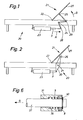
- a couch furniture frame is generally designated by the reference number 20.
- This reclining furniture has an adjustable head wedge 21.
- This head wedge 21 is articulated at a pivot point 22.
- the reference number 23 denotes the electric motor drive, a linear drive.
- the drive has a push or pull rod 3, which is also referred to as a push tube.
- This push tube 3 is articulated via a linkage arrangement with a pivot point 24 at 25 on the frame part 27 to be pivoted.
- the reference numerals 28 and 29 denote further, non-stationary articulation points of the individual link members. If the push tube moves in the direction of arrow A, the pivotable frame part 27 is pivoted in the direction of arrow B about the pivot point 22.
- FIG. 2 Another embodiment is shown in FIG. 2.
- the electromotive drive 23, which is firmly connected to the reclining furniture frame 20, is connected to its push or pressure pipe 3 via a swivel arm 30 mounted at the pivot point 24 with rollers 26.
- the pivotable frame part 27 rests on these rollers 26.
- These rollers 26 can be guided in a rail (not shown), so that here too the frame part 27 is forcibly guided in both directions of rotation.
- the pivoting part 27 can rest loosely on the rollers 26, so that the clockwise pivoting movement of the same takes place when the rollers 26 are lowered only by the action of gravity. It can also be seen here that a person can clamp between the same and the fixed frame part when the frame part 27 is lowered.
- FIG. 3 a sectional view of an embodiment of the electric motor drive is shown.
- the electric motor is generally designated by the reference number 7.
- the shaft of the electric motor 7 is connected to a worm 1.
- This worm 1 meshes with a worm wheel 2.
- This worm wheel is arranged on a sleeve 31.
- the sleeve 31 is supported by a roller bearing 32 in the housing 33.
- a tab 34 is connected to the housing 33 via cap screws 35.
- the drive is connected to the respective recliner furniture frame via this bracket 34.
- an annular space 36 is formed in the sleeve 31, in which an helical compression spring 9 serving as a return spring is arranged.
- the sleeve 31 is penetrated by a stub shaft 37, which with a Spindle 4 is rotatably connected.
- a truncated cone 6 is formed between the stub shaft 37 and the spindle 4, which truncated cone 6 forms a coupling half.
- the sleeve 31 has a frustoconical section 5 which overlaps the truncated cone 6 and forms the second coupling half.
- the spindle 4 runs in a sleeve 38 provided with an internal thread, via which the so-called push tube 3 is linearly displaced when the spindle 4 is rotated.
- the transmission elements which transmit the linear movement carried out by the push tube to the frame part to be adjusted, are articulated on the bracket 39.
- FIG. 4 in which a part of the sectional view of FIG. 3 is shown.
- the drive is designed in such a way that it has a safety device on tension when working on pressure.
- FIG. 1 In order to raise the frame part 27, that is to say the head part 21, the push tube 3 must exert a pressure. To pivot the frame part 27, the push tube 3 is therefore pressed by the rotation of the spindle 4 in the direction of arrow C of the lower illustration in FIG. 4. A counterforce thus arises, as is apparent to the person skilled in the art from the arrangements shown in FIGS. 1 and 2, which counterforce causes the truncated cone 6 connected to the spindle 4 to be pressed against the hollow truncated cone section 5 of the sleeve 31.
- the coupling halves 5 and 6 are in frictional engagement.
- the frame part 27 of FIG. 1 or 2 is now to be folded down.
- the direction of rotation of the spindle 4 is changed, for example, by changing the pole of the motor 7.
- the spindle now starts the thrust tube 3 from the lower position shown in FIG. 4, in which the front end of the thrust tube 3 facing the worm wheel 2 is at a distance from the housing of the motor or the worm gear against that in FIG. 4 withdraw the position shown above. If the frame part 27 is now opposed by, for example, a person jamming a limb under the frame part 27, a tensile force occurs in the push tube and thus in the spindle 4.
- the truncated cone 6 thus lifts off from the hollow truncated-cone-shaped section 5, so that there is a small space between their conical surfaces and the frictional engagement between these two coupling halves is thus eliminated.
- the frame part 27 will no longer pivot downward, although the motor 7 continues to drive. So that the pinched body part is not injured.
- FIG. 5 This figure shows an arrangement that is the reverse of that of FIG. 4, in that in the embodiment according to FIG. 5 the drive operates on a train and the fuse responds to pressure.
- the thrust tube 3 has the distance from the motor and transmission housing shown in the lower part of FIG. 5.
- the push tube 3 is pulled in the direction of arrow E.
- a counterforce thus arises again here, so that the truncated ball 6 is pulled into a frictional engagement against the frustoconical section 5. If the direction of rotation of the spindle 4 is now changed in order to pivot the frame part 27 down, the push tube 3 begins to move from the position shown in the upper part of FIG.
- FIG. 6 the Ab containing the helical compression spring 9 Section of the drive shown in FIG. 3 on an enlarged scale.
- the part of the stub shaft 37 is drawn which passes through the section of the sleeve 31 containing the helical compression spring 9.
- the helical compression spring 9 is arranged in an annular space 36 of the sleeve 31.
- a pressure bearing 8 is arranged between the front end of the sleeve 31 and a snap ring 40 seated in the stub shaft 37, here a roller bearing, ie a ball bearing.
- One race of the same rests on the sleeve 31 and the other race rests on the snap ring 40.
- the thrust bearing 8 can be inserted loosely.
- the helical compression spring 9 presses against the thrust bearing 8 and exerts a pressure on the snap ring 40.
- the two coupling halves, namely the truncated cone 6 and the frustoconical section 5 abut against one another with slight application of pressure. This ensures that there is also frictional engagement between the two coupling halves mentioned when the direction of rotation of the spindle 4 is such that the coupling is released when resistance occurs. It is evident that small frictional resistances due to the rod bearings and the pivot bearing of the pivotable frame part 27 must also be overcome in this working direction.
Abstract
Description
Die vorliegende Erfindung betrifft einen elektromotorischen Antrieb zum Verstellen des Kopf- oder Fusskeils eines Liegemöbels, welcher Antrieb einen Elektromotor aufweist, der über eine Schnecke ein Schneckenrad treibt, das seinerseits mit einer Gewindespindel antriebsverbunden ist, die in ein Schubrohr eingreift, derart, dass eine Rotationsbewegung des Elektromotors in eine lineare Bewegung des Schubrohres umgesetzt ist.The present invention relates to an electric motor drive for adjusting the head or foot wedge of a piece of reclining furniture, which drive has an electric motor which drives a worm wheel via a worm, which in turn is drive-connected to a threaded spindle which engages in a push tube in such a way that a rotational movement of the electric motor is converted into a linear movement of the push tube.
Zum elektromotorischen Verstellen eines Kopf- oder Fusskeils eines Liegemöbels wird üblicherweise ein sogenannter Linearantrieb verwendet. Dieser weist einen Schub-und Zugmotor auf, welcher mit dem Liegemöbel-Rahmen fest verbunden ist und eine linear verschiebbare Stange aufweist, welche üblicherweise über ein Gestänge mit dem zu verstellenden Teil verbunden ist. Dabei wird die Verstellbewegung über manuell zu betätigende Steuerorgane gesteuert. Bei den bekannten Antrieben ist eine Zwangsverbindung zwischen dem zu verstellenden Teil und dem Antriebsmotor vorhanden. Damit besteht die Gefahr, dass während des Betriebs der gesamten Verstellvorrichtung eine Person durch Unaufmerksamkeit beim Absenken des verstellbaren Liegemöbelkeiles Körperteile zwischen dem festen Liegemöbel-Rahmen und dem Liegemöbelkeil einklemmen kann.A so-called linear drive is usually used for the electromotive adjustment of a head or foot wedge of a piece of reclining furniture. This has a push and pull motor which is fixedly connected to the reclining furniture frame and has a linearly displaceable rod which is usually connected to the part to be adjusted via a linkage. The adjustment movement is controlled via manually operated control elements. In the known drives there is a positive connection between the part to be adjusted and the drive motor. Thus, there is a risk that during the operation of the entire adjusting a person can clamp iegemöbelkeil by inattention during the lowering of the adjustable reclining furniture wedge body parts between the fixed reclining furniture frame and the L.
Ziel der Erfindung ist, den angeführten Nachteil zu beheben.The aim of the invention is to remedy the disadvantage mentioned.
Der erfindungsgemässe elektromotorische Antrieb ist durch die Merkmale des Patentanspruches 1 gekennzeichnet.The electromotive drive according to the invention is characterized by the features of claim 1.
Nachfolgend wird der Erfindungsgegenstand anhand der Zeichnungen beispielsweise näher erläutert.The subject matter of the invention is explained in more detail below with reference to the drawings, for example.
Es zeigt:
- Fig. 1 einen ersten beispielsweisen Einsatz einer Verstellvorrichtung mit elektromotorischem Antrieb,
- Fig. 2 einen weiteren Einsatz einer Verstellvorrichtung mit elektromotorischem Antrieb,
- Fig. 3 einen Schnitt durch eine Ausführung eines elektromotorischen Antriebes,
- Fig. 4 die zwei Arbeitsstellungen des in der Fig.3 gezeigten elektromotorischen Antriebs,
- Fig. 5 eine der Fig. 4 gleichenden Darstellung einer weiteren Ausführung des elektromotorischen Antriebes, und
- Fig. 6 eine Einzelheit des elektromotorischen Antriebes der vorgängigen Ausführungen.
- 1 shows a first example of use of an adjusting device with an electric motor drive,
- 2 shows a further use of an adjusting device with an electric motor drive,
- 3 shows a section through an embodiment of an electric motor drive,
- 4 shows the two working positions of the electromotive drive shown in FIG. 3,
- 5 is a representation similar to FIG. 4 of a further embodiment of the electric motor drive, and
- Fig. 6 shows a detail of the electric motor drive of the previous versions.
In der Fig. 1 ist ein Liegemöbel-Rahmen allgemein mit der Bezugsziffer 20 bezeichnet. Dieses Liegemöbel weist einen verstellbaren Kopfkeil 21 auf. Dieser Kopfkeil 21 ist bei einer Schwenkstelle 22 angelenkt. Die Bezugsziffer 23 bezeichnet den elektromotorischen Antrieb, ein Linearantrieb. Der Antrieb weist eine Schub- bzw. Zugstange 3 auf, die auch als Schubrohr bezeichnet wird. Dieses Schubrohr 3 ist über eine Gestängeanordnung mit einem Drehpunkt 24 bei 25 am zu verschwenkenden Rahmenteil 27 angelenkt. Die Bezugsziffern 28 und 29 bezeichnen weitere, nicht ortsfeste Anlenkstellen der einzelnen Gestängeglieder. Bewegt sich das Schubrohr in Richtung des Pfeiles A, wird der schwenkbare Rahmenteil 27 in Richtung des Pfeiles B um die Schwenkstelle 22 geschwenkt. Bewegt sich das Schubrohr in der zu A entgegengesetzter Richtung, wird der Rahmenteil 27 heruntergeschwenkt. Es ist nun offensichtlich, dass eine Person, beispielsweise spielende Kinder beim Herunterschwenken des Rahmenteils 27 ein Körperglied zwischen diesem und dem feststehenden Rahmenteil einklemmen können und damit besteht eine erhebliche Verletzungsgefahr.In Fig. 1, a couch furniture frame is generally designated by the
Eine weitere Ausführung ist in der Fig. 2 gezeigt. Hier ist der mit dem Liegemöbel-Rahmen 20 fest verbundene elektromotorische Antrieb 23 mit seinem Schub- bzw. Druckrohr 3 über einen beim Drehpunkt 24 gelagerten Schwenkarm 30 mit Rollen 26 verbunden. Der schwenkbare Rahmenteil 27 liegt auf diesen Rollen 26 auf. Diese Rollen 26 können in einer (nicht gezeigten) Schiene geführt sein, so dass auch hier der Rahmenteil 27 in beiden Drehsinnen zwangsweise geführt ist. Alternativ kann der Schwenkteil 27 lose auf den Rollen 26 aufliegen, so dass die im Uhrzeigersinn erfolgende Schwenkbewegung desselben bei sich senkenden Rollen 26 lediglich durch Einwirkung der Schwerkraft erfolgt. Auch hier ist ersichtlich, dass eine Person bei sich absenkendem Rahmenteil 27 zwischen demselben und dem feststehenden Rahmenteil einklemmen kann.Another embodiment is shown in FIG. 2. Here, the
Es wird nun auf die Fig. 3 verwiesen, in welcher eine Schnittansicht einer Ausführung des elektromotorischen Antriebes dargestellt ist. Der Elektromotor ist allgemein mit der Bezugsziffer 7 bezeichnet. Die Welle des Elektromotors 7 ist mit einer Schnecke 1 verbunden. Diese Schnecke 1 kämmt mit einem Schneckenrad 2. Dieses Schnekkenrad ist auf einer Hülse 31 angeordnet. Die Hülse 31 ist über ein Wälzlager 32 im Gehäuse 33 abgestützt. Eine Lasche 34 ist über Kopfschrauben 35 mit dem Gehäuse 33 verbunden. Der Antrieb wird über diese Lasche 34 mit dem jeweiligen Liegemöbel-Rahmen verbunden. Beim in der Fig. 3 rechts liegenden Ende ist bei der Hülse 31 ein Ringraum 36 ausgebildet, in welchem eine als Rückstellfeder dienende Schraubendruckfeder 9 angeordnet ist. Die Hülse 31 ist von einer Stummelwelle 37 durchsetzt, welche mit einer Spindel 4 drehfest verbunden ist. Zwischen der Stummelwelle 37 und der Spindel 4 ist ein Kegelstumpf 6 ausgebildet, welcher Kegelstumpf 6 eine Kupplungshälfte bildet. Bei der gleichen Stelle weist die Hülse 31 einen den Kegelstumpf 6 übergreifenden hohlkegelstumpfförmigen Abschnitt 5 auf, welcher die zweite Kupplungshälfte bildet. Die Spindel 4 verläuft in einer mit einem Innengewinde versehenen Hülse 38, über welche beim Drehen der Spindel 4 das sogenannte Schubrohr 3 linear verschoben wird. Die Uebertragungsglieder, welche die vom Schubrohr durchgeführte lineare Bewegung auf den zu verstellenden Rahmenteil übertragen, sind an der Lasche 39 angelenkt.Reference is now made to FIG. 3, in which a sectional view of an embodiment of the electric motor drive is shown. The electric motor is generally designated by the reference number 7. The shaft of the electric motor 7 is connected to a worm 1. This worm 1 meshes with a
Es wird nun Bezug auf die Fig. 4 genommen, in welcher ein Teil der Schnittdarstellung der Fig. 3 wiedergegeben ist. Der Antrieb ist derart ausgebildet, dass er bei der sogenannten Arbeit auf Druck eine Sicherung auf Zug aufweist. Zur Erklärung dazu wird Bezug auf die Fig. 1 genommen. Um den Rahmenteil 27, also den Kopfteil 21 anzuheben, muss das Schubrohr 3 einen Druck ausüben. Zum Aufschwenken des Rahmenteils 27 wird daher das Schubrohr 3 durch die Rotation der Spindel 4 in Richtung des Pfeiles C der unteren Darstellung der Fig. 4 gedrückt. Es stellt sich somit eine Gegenkraft ein, wie dies aus den in den Fig. 1 und 2 gezeigten Anordnungen dem Fachmann offensichtlich ist, welche Gegenkraft bewirkt, dass der mit der Spindel 4 verbundene Kegelstumpf 6 gegen den hohlkegelstumpfförmigen Abschnitt 5 der Hülse 31 gepresst wird. Somit sind die Kupplungshälften 5 und 6 im Reibeingriff.Reference is now made to FIG. 4, in which a part of the sectional view of FIG. 3 is shown. The drive is designed in such a way that it has a safety device on tension when working on pressure. To explain this, reference is made to FIG. 1. In order to raise the
Es soll nun der Rahmenteil 27 der Fig. 1 oder 2 hinuntergeklappt werden. Dazu wird die Drehrichtung der Spindel 4 beispielsweise durch Polumschaltung des Motors 7 gewechselt. Die Spindel beginnt nun das Schubrohr 3 aus der in der Fig. 4 ersichtlichen unteren Stellung, bei der das stirnseitige, dem Schneckenrad 2 zugekehrte Ende des Schubrohres 3 vom Gehäuse des Motors bzw. des Schneckengetriebes einen Abstand aufweist gegen die in der Fig. 4 oben gezeigte Stellung zurückzuziehen. Wird nun dem Rahmenteil 27 ein Widerstand entgegengesetzt, indem beispielsweise eine Person ein Gliedmass unter dem Rahmenteil 27 einklemmt, tritt beim Schubrohr und somit bei der Spindel 4 eine Zugkraft auf. Damit hebt sich der Kegelstumpf 6 vom hohlkegelstumpfförmigen Abschnitt 5 ab, so dass ein kleiner Zwischenraum zwischen deren konischen Flächen entsteht und damit wird der Reibeingriff zwischen diesen zwei Kupplungshälften aufgehoben. Damit wird sich der Rahmenteil 27 nicht mehr weiter nach unten schwenken, obwohl der Motor 7 weiter treibt. Damit wird der eingeklemmte Körperteil nicht verletzt.The
Es wird nun auf die Fig. 5 verwiesen. Diese Figur zeigt eine im Vergleich mit der Fig. 4 umgekehrte Anordnung, indem bei der Ausführung nach der Fig. 5 der Antrieb auf Zug arbeitet und die Sicherung auf Druck anspricht. Das heisst, dass z.B. in der heruntergeklappten Stellung des Rahmenteiles 27 das Schubrohr 3 den im unteren Teil der Fig. 5 gezeigten Abstand vom Motor- und Getriebegehäuse aufweist. Zum Aufklappen des Rahmenteils 27 wird das Schubrohr 3 in Richtung des Pfeiles E gezogen. Es stellt sich somit auch hier wieder eine Gegenkraft ein, so dass der Kugelstumpf 6 gegen den hohlkegelstumpfförmigen Abschnitt 5 in einen Reibeingriff gezogen wird. Wird nun der Drehsinn der Spindel 4 gewechselt, um den Rahmenteil 27 herunterzuschwenken, beginnt sich das Schubrohr 3 aus der im oberen Teil der Fig. 5 gezeigten Stellung in Richtung des Pfeiles F zu bewegen. Wird nun bei der in der Richtung des Pfeiles F erfolgenden Bewegung des Schubrohres 3 ein Widerstand auftreten, entsteht eine Druckeinwirkung auf das Schubrohr 3 und die Spindel 4 und damit hebt sich der Kegelstumpf 6 vom hohlkegelstumpfförmigen Abschnitt 5 auf und die Kupplung ist gelöst. Damit wird eine weitere Bewegung des Schubrohres 3 unterbrochen.Reference is now made to FIG. 5. This figure shows an arrangement that is the reverse of that of FIG. 4, in that in the embodiment according to FIG. 5 the drive operates on a train and the fuse responds to pressure. This means that e.g. in the folded-down position of the
Es wird nun auf die Fig. 6 verwiesen. In dieser Figur ist der die Schraubendruckfeder 9 enthaltende Abschnitt des Antriebs gemäss der Fig. 3 in vergrössertem Massstab dargestellt. Insbesondere ist der Teil der Stummelwelle 37 gezeichnet, der den die Schraubendruckfeder 9 enthaltende Abschnitt der Hülse 31 durchsetzt. Die Schraubendruckfeder 9 ist in einem Ringraum 36 der Hülse 31 angeordnet. Zwischen dem stirnseitigen Ende der Hülse 31 und einem in der Stummelwelle 37 sitzenden Sprengring 40 ist ein Drucklager 8 angeordnet, hier ein Wälzlager, d.h. ein Kugellager. Der eine Laufring desselben liegt an der Hülse 31 an und der andere Laufring liegt am Sprengring 40 an. Das Drucklager 8 kann lose eingesetzt sein. Die Schraubendruckfeder 9 drückt gegen das Drucklager 8 und bewirkt die Ausübung eines Druckes auf den Sprengring 40. Das heisst, dass (siehe Figur) die zwei Kupplungshälften, nämlich Kegelstumpf 6 und hohlkegelstumpfförmiger Abschnitt 5 unter leichter Druckausübung aneinander anliegen. Dieses stellt sicher, dass auch dann ein Reibeingriff zwischen den zwei genannten Kupplungshälften vorhanden ist, wenn der Drehsinn der Spindel 4 derart ist, dass sich bei Auftreten eines Widerstandes die Kupplung löst. Es ist offendichtlich, dass auch in dieser genannten Arbeitsrichtung kleine Reibwiderstände aufgrund der Gestängelagerungen, der Schwenklagerung des schwenkbaren Rahmenteils 27 überwunden werden müssen.Reference is now made to FIG. 6. In this figure, the Ab containing the
Stellt sich nun der gehemmte Betriebszustand ein, bei dem die Kupplung gelöst wird, welcher Zustand beispielsweise in den Figuren 3 und 4 oben dargestellt ist, hat sich die Stummelwelle 37 in Richtung des Pfeiles G der Figur 6 nach links bewegt. Damit liegt der Sprengring 40 satt am Drucklager 8 an dieses seinerseits satt an der Hülse 31 an. Damit ist die Rotation des Schneckenrades 2 und somit des Motors 7 auch im Leerlauf abgesichert.If the inhibited operating state now arises, in which the clutch is released, which state is shown, for example, in FIGS. 3 and 4 above, the
Claims (3)
Priority Applications (1)
| Application Number | Priority Date | Filing Date | Title |
|---|---|---|---|
| AT84115781T ATE41856T1 (en) | 1983-12-22 | 1984-12-19 | ELECTROMORIC DRIVE FOR ADJUSTING THE HEAD OR FOOT WEDGE OF LOUNGE FURNITURE. |
Applications Claiming Priority (2)
| Application Number | Priority Date | Filing Date | Title |
|---|---|---|---|
| CH6863/83 | 1983-12-22 | ||
| CH6863/83A CH665942A5 (en) | 1983-12-22 | 1983-12-22 | ELECTRIC MOTOR DRIVE FOR ADJUSTING THE HEAD OR FOOT WEDGE OF A FURNITURE. |
Publications (3)
| Publication Number | Publication Date |
|---|---|
| EP0146914A2 true EP0146914A2 (en) | 1985-07-03 |
| EP0146914A3 EP0146914A3 (en) | 1987-04-08 |
| EP0146914B1 EP0146914B1 (en) | 1989-04-05 |
Family
ID=4316214
Family Applications (1)
| Application Number | Title | Priority Date | Filing Date |
|---|---|---|---|
| EP84115781A Expired EP0146914B1 (en) | 1983-12-22 | 1984-12-19 | Electromotoric drive for adjusting the head and foot support of lying furniture |
Country Status (4)
| Country | Link |
|---|---|
| EP (1) | EP0146914B1 (en) |
| AT (1) | ATE41856T1 (en) |
| CH (1) | CH665942A5 (en) |
| DE (1) | DE3477540D1 (en) |
Cited By (13)
| Publication number | Priority date | Publication date | Assignee | Title |
|---|---|---|---|---|
| GB2205232A (en) * | 1987-05-28 | 1988-12-07 | Egerton Hospital Equip | Bed with hinged panel safety feature |
| EP0606575A1 (en) * | 1993-01-15 | 1994-07-20 | Dewert Antriebs- und Systemtechnik GmbH & Co. KG | Lifting device |
| GB2275185A (en) * | 1993-02-02 | 1994-08-24 | Sichelschmidt Stanzwerk | An adjustable bed/seat in the form of an ottoman or recamiere |
| DE4433934A1 (en) * | 1994-09-23 | 1996-03-28 | Micas Gmbh & Co Kg | Furniture adjuster for e.g. bed ends and chairs |
| EP0968675A1 (en) * | 1998-06-29 | 2000-01-05 | Dewert Antriebs- und Systemtechnik GmbH & Co. KG | Electrically acuated drive for furniture |
| EP0994553A1 (en) * | 1998-10-12 | 2000-04-19 | Dewert Antriebs- und Systemtechnik GmbH & Co. KG | Electrically powered drive for furniture |
| EP1231412A3 (en) * | 2001-02-08 | 2003-08-20 | Linak A/S | A linear actuator |
| WO2004028305A1 (en) * | 2002-09-16 | 2004-04-08 | Dewert Antriebs- Und Systemtechnik Gmbh & Co. Kg | Electromotive furniture drive |
| EP1561970A3 (en) * | 2004-02-09 | 2008-06-11 | Ludwig Ehrhardt GmbH | Linear actuator |
| EP2080933A1 (en) | 2008-01-15 | 2009-07-22 | JTEKT Corporation | Ball screw unit |
| EP2172672A1 (en) * | 2008-10-02 | 2010-04-07 | Rational AG | Drive device for connecting a motorised drive unit with a lifting cylinder, method for connecting a motorised drive unit with a lifting cylinder and food treatment device |
| WO2010149558A1 (en) * | 2009-06-23 | 2010-12-29 | Magna Powertrain Ag & Co Kg | Actuator |
| US8375814B2 (en) | 2009-01-28 | 2013-02-19 | Stabilus Gmbh | Drive device |
Families Citing this family (2)
| Publication number | Priority date | Publication date | Assignee | Title |
|---|---|---|---|---|
| DE102004058152C5 (en) * | 2004-12-02 | 2008-04-24 | OKIN Gesellschaft für Antriebstechnik mbH | Bearing seat and drive unit |
| DE102012211508A1 (en) * | 2012-07-03 | 2014-01-09 | Dewertokin Gmbh | Device for controlling a furniture drive |
Citations (3)
| Publication number | Priority date | Publication date | Assignee | Title |
|---|---|---|---|---|
| FR1439800A (en) * | 1965-04-23 | 1966-05-20 | Bedframe | |
| FR2351629A1 (en) * | 1976-05-21 | 1977-12-16 | Hanning Elektro Werke | ELECTROMECHANICAL ADJUSTMENT DEVICE INTENDED FOR BED SUMMERS |
| CH615333A5 (en) * | 1977-04-04 | 1980-01-31 | Magnetic Elektromotoren Ag | Drive for an adjusting device of a bedstead |
-
1983
- 1983-12-22 CH CH6863/83A patent/CH665942A5/en not_active IP Right Cessation
-
1984
- 1984-12-19 AT AT84115781T patent/ATE41856T1/en not_active IP Right Cessation
- 1984-12-19 DE DE8484115781T patent/DE3477540D1/en not_active Expired
- 1984-12-19 EP EP84115781A patent/EP0146914B1/en not_active Expired
Patent Citations (3)
| Publication number | Priority date | Publication date | Assignee | Title |
|---|---|---|---|---|
| FR1439800A (en) * | 1965-04-23 | 1966-05-20 | Bedframe | |
| FR2351629A1 (en) * | 1976-05-21 | 1977-12-16 | Hanning Elektro Werke | ELECTROMECHANICAL ADJUSTMENT DEVICE INTENDED FOR BED SUMMERS |
| CH615333A5 (en) * | 1977-04-04 | 1980-01-31 | Magnetic Elektromotoren Ag | Drive for an adjusting device of a bedstead |
Cited By (16)
| Publication number | Priority date | Publication date | Assignee | Title |
|---|---|---|---|---|
| GB2205232A (en) * | 1987-05-28 | 1988-12-07 | Egerton Hospital Equip | Bed with hinged panel safety feature |
| GB2205232B (en) * | 1987-05-28 | 1991-04-03 | Egerton Hospital Equip | Bed with hinged panel safety feature |
| EP0606575A1 (en) * | 1993-01-15 | 1994-07-20 | Dewert Antriebs- und Systemtechnik GmbH & Co. KG | Lifting device |
| GB2275185A (en) * | 1993-02-02 | 1994-08-24 | Sichelschmidt Stanzwerk | An adjustable bed/seat in the form of an ottoman or recamiere |
| GB2275185B (en) * | 1993-02-02 | 1996-11-06 | Sichelschmidt Stanzwerk | An adjustable bed/seat |
| DE4433934A1 (en) * | 1994-09-23 | 1996-03-28 | Micas Gmbh & Co Kg | Furniture adjuster for e.g. bed ends and chairs |
| EP0968675A1 (en) * | 1998-06-29 | 2000-01-05 | Dewert Antriebs- und Systemtechnik GmbH & Co. KG | Electrically acuated drive for furniture |
| EP0994553A1 (en) * | 1998-10-12 | 2000-04-19 | Dewert Antriebs- und Systemtechnik GmbH & Co. KG | Electrically powered drive for furniture |
| EP1231412A3 (en) * | 2001-02-08 | 2003-08-20 | Linak A/S | A linear actuator |
| WO2004028305A1 (en) * | 2002-09-16 | 2004-04-08 | Dewert Antriebs- Und Systemtechnik Gmbh & Co. Kg | Electromotive furniture drive |
| EP1561970A3 (en) * | 2004-02-09 | 2008-06-11 | Ludwig Ehrhardt GmbH | Linear actuator |
| EP2080933A1 (en) | 2008-01-15 | 2009-07-22 | JTEKT Corporation | Ball screw unit |
| US8424402B2 (en) | 2008-01-15 | 2013-04-23 | Jtekt Corporation | Ball screw unit |
| EP2172672A1 (en) * | 2008-10-02 | 2010-04-07 | Rational AG | Drive device for connecting a motorised drive unit with a lifting cylinder, method for connecting a motorised drive unit with a lifting cylinder and food treatment device |
| US8375814B2 (en) | 2009-01-28 | 2013-02-19 | Stabilus Gmbh | Drive device |
| WO2010149558A1 (en) * | 2009-06-23 | 2010-12-29 | Magna Powertrain Ag & Co Kg | Actuator |
Also Published As
| Publication number | Publication date |
|---|---|
| EP0146914A3 (en) | 1987-04-08 |
| DE3477540D1 (en) | 1989-05-11 |
| EP0146914B1 (en) | 1989-04-05 |
| ATE41856T1 (en) | 1989-04-15 |
| CH665942A5 (en) | 1988-06-30 |
Similar Documents
| Publication | Publication Date | Title |
|---|---|---|
| EP0146914B1 (en) | Electromotoric drive for adjusting the head and foot support of lying furniture | |
| DE10017978C2 (en) | Furniture drive | |
| EP1294255B1 (en) | Furniture drive device for moving parts of a piece of furniture in relation to each other | |
| DE102014115033A1 (en) | Electromotive adjustable support device | |
| CH658029A5 (en) | DEVICE FOR TENSIONING, SEALING AND CUTTING PLASTIC TAPES FOR PACKAGE STRAPS. | |
| DE3102402C2 (en) | ||
| DE2141276A1 (en) | DRIVE AND BRAKE DEVICE FOR AN OPEN-END SPINNING UNIT | |
| EP2974622A1 (en) | Support device adjustable with an electric motor | |
| DE102016116253A1 (en) | Electromotive double drive | |
| EP0364394A2 (en) | Bed for adjustably keeping the legs of a person lying on it in a high position | |
| CH683496A5 (en) | Drive for displacement of movable part of mechanism | |
| DE4416689C9 (en) | Bed, partic. hospital bed | |
| EP0486984A1 (en) | Device for tightening a driving belt | |
| DE2531112A1 (en) | HEIGHT ADJUSTABLE BED | |
| DE102004016050B4 (en) | Electromotive furniture drive for adjusting parts of a furniture relative to each other | |
| DE102020131206A1 (en) | Support device adjustable by electric motor | |
| DE10046752C1 (en) | Double drive for furniture adjustment has support face for actuator lower than pivot axis, to support pivot lever | |
| EP1285645B1 (en) | Bath lift for elderly and disabled persons | |
| DE2834617C3 (en) | Double block wire accumulator | |
| DE19921300A1 (en) | Adjustment device for furniture of the living, working or care area which has an adjustable element | |
| DE834657C (en) | Automatic speed change gearbox for light vehicles, such as bicycles with auxiliary motor or the like. | |
| EP0079998A1 (en) | Frame for sitting and sleeping furniture | |
| DE102020131204A1 (en) | Support device adjustable by electric motor | |
| DE102016116251A1 (en) | Electromotive double drive | |
| CH692805A5 (en) | Patient position manual adjusting device for a hospital trolley |
Legal Events
| Date | Code | Title | Description |
|---|---|---|---|
| PUAI | Public reference made under article 153(3) epc to a published international application that has entered the european phase |
Free format text: ORIGINAL CODE: 0009012 |
|
| AK | Designated contracting states |
Designated state(s): AT BE CH DE FR GB IT LI LU NL SE |
|
| PUAL | Search report despatched |
Free format text: ORIGINAL CODE: 0009013 |
|
| AK | Designated contracting states |
Kind code of ref document: A3 Designated state(s): AT BE CH DE FR GB IT LI LU NL SE |
|
| 17P | Request for examination filed |
Effective date: 19870926 |
|
| 17Q | First examination report despatched |
Effective date: 19880603 |
|
| GRAA | (expected) grant |
Free format text: ORIGINAL CODE: 0009210 |
|
| ITF | It: translation for a ep patent filed |
Owner name: BARZANO' E ZANARDO ROMA S.P.A. |
|
| AK | Designated contracting states |
Kind code of ref document: B1 Designated state(s): AT BE CH DE FR GB IT LI LU NL SE |
|
| PG25 | Lapsed in a contracting state [announced via postgrant information from national office to epo] |
Ref country code: SE Effective date: 19890405 Ref country code: NL Effective date: 19890405 Ref country code: GB Effective date: 19890405 Ref country code: BE Effective date: 19890405 |
|
| REF | Corresponds to: |
Ref document number: 41856 Country of ref document: AT Date of ref document: 19890415 Kind code of ref document: T |
|
| REF | Corresponds to: |
Ref document number: 3477540 Country of ref document: DE Date of ref document: 19890511 |
|
| ET | Fr: translation filed | ||
| NLV1 | Nl: lapsed or annulled due to failure to fulfill the requirements of art. 29p and 29m of the patents act | ||
| GBV | Gb: ep patent (uk) treated as always having been void in accordance with gb section 77(7)/1977 [no translation filed] | ||
| PG25 | Lapsed in a contracting state [announced via postgrant information from national office to epo] |
Ref country code: AT Effective date: 19891219 |
|
| PG25 | Lapsed in a contracting state [announced via postgrant information from national office to epo] |
Ref country code: LU Free format text: LAPSE BECAUSE OF NON-PAYMENT OF DUE FEES Effective date: 19891231 |
|
| PLBE | No opposition filed within time limit |
Free format text: ORIGINAL CODE: 0009261 |
|
| STAA | Information on the status of an ep patent application or granted ep patent |
Free format text: STATUS: NO OPPOSITION FILED WITHIN TIME LIMIT |
|
| 26N | No opposition filed | ||
| PGFP | Annual fee paid to national office [announced via postgrant information from national office to epo] |
Ref country code: FR Payment date: 19921125 Year of fee payment: 9 |
|
| PGFP | Annual fee paid to national office [announced via postgrant information from national office to epo] |
Ref country code: DE Payment date: 19921211 Year of fee payment: 9 |
|
| ITTA | It: last paid annual fee | ||
| PG25 | Lapsed in a contracting state [announced via postgrant information from national office to epo] |
Ref country code: FR Effective date: 19940831 |
|
| PG25 | Lapsed in a contracting state [announced via postgrant information from national office to epo] |
Ref country code: DE Effective date: 19940901 |
|
| REG | Reference to a national code |
Ref country code: FR Ref legal event code: ST |
|
| PGFP | Annual fee paid to national office [announced via postgrant information from national office to epo] |
Ref country code: CH Payment date: 19941216 Year of fee payment: 11 |
|
| PG25 | Lapsed in a contracting state [announced via postgrant information from national office to epo] |
Ref country code: LI Effective date: 19951231 Ref country code: CH Effective date: 19951231 |
|
| REG | Reference to a national code |
Ref country code: CH Ref legal event code: PL |