EP0146820A1 - Comminuter for turnings - Google Patents
Comminuter for turnings Download PDFInfo
- Publication number
- EP0146820A1 EP0146820A1 EP84114517A EP84114517A EP0146820A1 EP 0146820 A1 EP0146820 A1 EP 0146820A1 EP 84114517 A EP84114517 A EP 84114517A EP 84114517 A EP84114517 A EP 84114517A EP 0146820 A1 EP0146820 A1 EP 0146820A1
- Authority
- EP
- European Patent Office
- Prior art keywords
- crusher
- housing
- rotor
- knife
- chip
- Prior art date
- Legal status (The legal status is an assumption and is not a legal conclusion. Google has not performed a legal analysis and makes no representation as to the accuracy of the status listed.)
- Granted
Links
Images


Classifications
-
- B—PERFORMING OPERATIONS; TRANSPORTING
- B02—CRUSHING, PULVERISING, OR DISINTEGRATING; PREPARATORY TREATMENT OF GRAIN FOR MILLING
- B02C—CRUSHING, PULVERISING, OR DISINTEGRATING IN GENERAL; MILLING GRAIN
- B02C18/00—Disintegrating by knives or other cutting or tearing members which chop material into fragments
- B02C18/06—Disintegrating by knives or other cutting or tearing members which chop material into fragments with rotating knives
- B02C18/16—Details
- B02C18/18—Knives; Mountings thereof
-
- B—PERFORMING OPERATIONS; TRANSPORTING
- B02—CRUSHING, PULVERISING, OR DISINTEGRATING; PREPARATORY TREATMENT OF GRAIN FOR MILLING
- B02C—CRUSHING, PULVERISING, OR DISINTEGRATING IN GENERAL; MILLING GRAIN
- B02C18/00—Disintegrating by knives or other cutting or tearing members which chop material into fragments
- B02C18/06—Disintegrating by knives or other cutting or tearing members which chop material into fragments with rotating knives
Definitions
- the invention relates to a chip crusher with a rotor arranged drivably in the crusher housing, on the inlet side of which at least one pre-crushing arm is arranged, the pre-crushing knife cooperates with crushing bars arranged on the crusher housing and on the outlet side several rotor knives of a fine crusher distributed over the circumference, the breaking edges of which are arranged interact with the breaking edges of several stator knives distributed over the circumference in the crusher housing.
- a chip breaker of this type is known from DE-OS 25 47 980.
- the crusher housing is U-shaped or trough-shaped in cross section at right angles to the rotor axis, and the upper flat side of the crusher housing is designed as a lid that can be opened.
- the inner wall of the crusher housing runs essentially parallel to the rotor axis.
- the chip breaker has no restriction in the direction of the material flow.
- the rotor is driven by a slip clutch so that nothing is destroyed if the rotor is overloaded or blocked.
- the drive is controlled so that the direction of rotation is changed when the rotor is blocked so that the rotor can work freely again.
- the present invention has for its object to provide a chip breaker in which the removal of a coarse part causing a blockage of the rotor is made possible quickly and without effort.
- this object is achieved according to the invention in that at least one stator knife in the crusher housing is guided in a radially movable manner from an operating position into an opening position which releases a coarse part outlet.
- a coarse part for example a rod end piece, blocks the rotor in the chip breaker according to the invention because it has become jammed between the rotor knife and the stator knife, the coarse part is removed by changing the direction of rotation of the rotor and releasing the coarse part outlet.
- the radially movable stator knife is held in the working position by a drive, for example by a hydraulic cylinder.
- a drive for example by a hydraulic cylinder.
- the coarse part outlet is advantageously arranged at the deepest point of the crusher chamber, namely in the region of the lowest casing surface line.
- the chip crusher according to FIG. 1 has a precher housing 1 in which a rotor 2 is drivably mounted.
- the rotor 2 has a pre-breaking arm 3 with a pre-breaking knife 4, the breaking edges of which cooperate with the breaking edges of breaking bars 5, which are fixedly arranged in the breaker housing 1.
- rotor knives 6 of a fine crusher are arranged on the rotor, the breaking edges of which cooperate with the breaking edges of a plurality of stator knives 7 distributed over the circumference in the crusher housing 1.
- the chips to be crushed pass from the hopper 8 into the crusher housing 1, where they are gripped by the pre-crushing arm 3 and broken between the crushing bars 5 and the pre-crushing knife 4 sliding past them at a distance.
- the block 14 is conical and is pressed into a correspondingly conical guide 17 which is placed on the crusher housing 1 and which absorbs the shear forces which act on the stator blades 7 '.
- the stator blades 7 ' are blocked hydraulically by means of the piston-cylinder unit 15. If a coarse part causes a blockage of the rotor, this coarse part can be removed from the crusher chamber by opening the coarse part outlet and reversing the drive of the rotor. The coarse part passes through the coarse part outlet 10 'onto the outlet chute 11. Canach, the stator blades 7' are pressed back into their working position and the chip breaker can resume its normal operation.
- the rotor rotates, for example, at a speed of 60 to 80 rpm.
- the rotor drive is controlled to reverse three to four times. If the rotor has not yet cleared itself, the piston-cylinder drive 15 is given an impulse to open the coarse part outlet 10 'by pulling back the radially movable stator blades 7'. The rotor is then driven reversibly at a speed of 2 to 4 rpm, for example. It has been shown that in most cases the coarse part causing the blocking moves to the open coarse part outlet 10 'and leaves the crusher chamber.
- the chip crusher must be switched off and the cover 12 opened towards the crusher chamber.
- signal generators are attached to this chip breaker, which give an optical and acoustic signal when, after opening the coarse part outlet 10 'and after the motor has been reversed several times, the rotor has not yet cleared itself.
- the housing cover 12 can be opened with a handle and the crusher chamber can be cleared by hand.
- the rotor 2 is fastened to a rotor shaft which is mounted in a frame 13 via a slide bearing and a rolling element bearing.
- the outlet chute 11 is arranged between the crusher housing 1 and the frame 13.
- a co-rotating wiper 30 is arranged on the underside of the rotor and pushes the broken chips out of the outlet space 10 so that they reach the outlet chute 11.
- stator knife 7 ' is arranged to be radially movable.
- This stator knife 7 ' is attached via a block 14 to a rigid lever 18 which is pivotally mounted on the crusher housing 1 about the axis 19 and which can be moved into an open position and a closed position by a piston-cylinder drive 15 via the piston rod 16 . So that the shear forces acting on the stator knife 7 'during chip breaking do not have to be absorbed by the bearing 19, the stator knife 7 1 and the associated block 14 are guided in a guide 17 which is placed on the crusher housing 1.
- the length of the lever 18 corresponds approximately to the diameter of the chip breaker, so that the cylinder-piston drive 15, which is supported against a bracket 20, can be arranged on one side of the chip breaker.
- stator knives 7 1 are arranged to be axially movable, but also the wall 24 of the crusher housing 1 adjoining this stator knife 7 1 and a part 23 of the ceiling 22 of the outlet mouth 21.
- the radially displaceable part 24 of the wall of the crusher housing 1 and the displaceable part 23 of the ceiling 22 of the outlet mouth 21 form with guide walls 26 a slide 25 which is guided radially in a guide housing 27 in relation to the rotor axis 9.
- this guide housing 27 there is the piston-cylinder unit 15, the cylinder of which is rigidly attached to a wall of the housing 27.
Abstract
Es handelt sich um einen Spänebrecher mit einem im Brechergehäuse (1) antreibbar angeordneten Rotor (2), an dem einlaßseitig mindestens ein Vorbrecharm (3) angeordnet ist, dessen Vorbrechmesser (4) mit am Brechergehäuse angeordneten Brechleisten (5) zusammenwirkt, und an dem auslaßseitig mehrere über den Umfang verteilte Rotormesser (6) eines Feinbrechwerkes angeordnet sind, deren Brechkanten mit den Brechkanten mehrerer im Brechergehäuse (1) über den Umfang verteilt angeordneter Statormesser (7) zusammenwirken. Damit Grobteile, die das Feinbrechwerk blockieren, aus dem Brechergehäuse entfernt werden können, ist mindestens ein Statormesser (7') aus seiner Arbeitsstellung in eine einen Grobteilauslaß (10') freigebende Öffnungsstellung im Brechergehäuse (1) radial beweglich geführt.It is a chip crusher with a rotor (2) drivably arranged in the crusher housing (1), on the inlet side of which at least one pre-crushing arm (3) is arranged, the pre-crushing knife (4) of which cooperates with crushing bars (5) arranged on the crusher housing, and on which On the outlet side, a plurality of rotor knives (6) of a fine crusher distributed over the circumference are arranged, the breaking edges of which cooperate with the breaking edges of several stator knives (7) distributed over the circumference in the crusher housing (1). So that coarse parts, which block the fine crusher, can be removed from the crusher housing, at least one stator knife (7 ') is guided from its working position into an open position in the crusher housing (1) which releases a coarse part outlet (10').
Description
Die Erfindung bezieht sich auf einen Spänebrecher mit einem im Brechergehäuse antreibbar angeordneten Rotor, an dem einlaßseitig mindestens ein Vorbrecharm angeordnet ist, dessen Vorbrechmesser mit am Brechergehäuse angeordneten Brechleisten zusammenwirkt und an dem auslaßseitig mehrere, über den Umfang verteilte Rotormesser eines Feinbrechwerkes angeordnet sind, deren Brechkanten mit den Brechkanten mehrerer, im Brechergehäuse über den Umfang verteilt angeordneter Statormesser zusammenwirken.The invention relates to a chip crusher with a rotor arranged drivably in the crusher housing, on the inlet side of which at least one pre-crushing arm is arranged, the pre-crushing knife cooperates with crushing bars arranged on the crusher housing and on the outlet side several rotor knives of a fine crusher distributed over the circumference, the breaking edges of which are arranged interact with the breaking edges of several stator knives distributed over the circumference in the crusher housing.
Ein Spänebrecher dieser Art ist aus der DE-OS 25 47 980 bekannt. Bei diesem Spänebrecher ist das Brechergehäuse im Querschnitt rechtwinklig zur Rotorachse U- oder trogförmig ausgebildet und die obere flache Seite des Brechergehäuses ist als zu öffnender Deckel ausgebildet. Die Innenwandung des Brechergehäuses verläuft im wesentlichen parallel zur Rotorachse. Dadurch hat der Spänebrecher in Richtung des Materialflusses keine Einengung. Der Rotor wird über eine Rutschkupplung angetrieben, damit bei Überlastung oder bei Blockierung des Rotors nichts zerstört wird. Der Antrieb ist so gesteuert, daß bei Blockieren des Rotors die Drehrichtung geändert wird, damit sich der Rotor wieder freiarbeiten kann. Bei diesem reversierenden Antrieb können auch Grobteile, die im Feinbrechwerk den Rotor blockierten, zum Auslaß gelangen. Diese Maßnahme führt aber nicht immer zum Ziel, insbesondere dann, wenn das Grobteil größer ist als die Lücken zwischen dem Rotormesser und Statormesser des Feinbrechwerkes. In diesem Fall muß der Spänebrecher abgeschaltet und der Gehäusedeckel geöffnet werden, so daß der Brecherraum zumindest teilweise von Hand entleert werden kann und das Grobteil aus dem Brecherraum herausgenommen werden kann. Wegen der Scharfkantigkeit der Späne müssen während dieser Arbeit Schutzhandschuhe getragen werden. Diese Arbeiten sind zeitaufwendig und führen deshalb zu längeren Stillstandzeiten der Maschine.A chip breaker of this type is known from DE-OS 25 47 980. In this chip crusher, the crusher housing is U-shaped or trough-shaped in cross section at right angles to the rotor axis, and the upper flat side of the crusher housing is designed as a lid that can be opened. The inner wall of the crusher housing runs essentially parallel to the rotor axis. As a result, the chip breaker has no restriction in the direction of the material flow. The rotor is driven by a slip clutch so that nothing is destroyed if the rotor is overloaded or blocked. The drive is controlled so that the direction of rotation is changed when the rotor is blocked so that the rotor can work freely again. With this reversing drive, coarse parts that blocked the rotor in the fine crusher can also reach the outlet. However, this measure does not always lead to the goal, especially if the coarse part is larger than the gaps between the rotor knife and stator knife of the fine crusher. In this case, the chip crusher must be switched off and the housing cover opened so that the crusher space can be at least partially emptied by hand and the coarse part can be removed from the crusher room. Because of the sharp edges of the chips, protective gloves must be worn during this work. This work is time-consuming and therefore leads to longer machine downtimes.
Der vorliegenden Erfindung liegt die Aufgabe zugrunde, einen Spänebrecher zu schaffen, bei dem das Entfernen eines eine Blockade des Rotors bewirkenden Grobteiles schnell und ohne Aufwand ermöglicht ist.The present invention has for its object to provide a chip breaker in which the removal of a coarse part causing a blockage of the rotor is made possible quickly and without effort.
Ausgehend'von einemSpänebrecher der eingangs genannten Art wird diese Aufgabe erfindungsgemäß dadurch gelöst, daß mindestens ein Statormesser im Brechergehäuse von einer Arbeitsstellung in eine einen Grobteilauslaß freigebende öffnungsstellung radial beweglich geführt ist.Starting from a chip crusher of the type mentioned at the outset, this object is achieved according to the invention in that at least one stator knife in the crusher housing is guided in a radially movable manner from an operating position into an opening position which releases a coarse part outlet.
Wenn bei dem erfindungsgemäßen Spänebrecher ein Grobteil, zum Beispiel ein Stangenendstück, den Rotor blockiert, weil es sich zwischen Rotormesser und Statormesser eingeklemmt hat, wird durch wechselnde Drehrichtung des Rotors und Freigeben des Grobteilauslasses das Grobteil entfernt.If a coarse part, for example a rod end piece, blocks the rotor in the chip breaker according to the invention because it has become jammed between the rotor knife and the stator knife, the coarse part is removed by changing the direction of rotation of the rotor and releasing the coarse part outlet.
Das radial bewegliche Statormesser wird über einen Antrieb, beispielsweise über einen Hydraulikzylinder, in Arbeitsstellung gehalten. Wenn eine Blockade auftritt und ein Grobteil den Auslaß passieren soll, wird das radial bewegliche Statormesser nach außen bewegt, wodurch eine Passage für das Grobteil frei wird.The radially movable stator knife is held in the working position by a drive, for example by a hydraulic cylinder. When a blockage occurs and a coarse part is to pass through the outlet, the radially movable stator knife is moved outwards, thereby clearing a passage for the coarse part.
Bei einem Spänebrecher mit zur Vertikalen geneigten Rotorachse ist der Grobteilauslaß vorteilhafterweise an der tiefsten Stelle des Brecherraumes angeordnet, nämlich im Bereich der untersten Gehäusemantellinie.In the case of a chip crusher with the rotor axis inclined to the vertical, the coarse part outlet is advantageously arranged at the deepest point of the crusher chamber, namely in the region of the lowest casing surface line.
Weitere Merkmale der Erfindung ergeben sich aus den Unteransprüchen.Further features of the invention emerge from the subclaims.
In der folgenden Beschreibung werden Ausführungsbeispiele des erfindungsgemäßen Spänebrechers unter Bezugnahme auf die Zeichnungen näher erläutert. DieZeichnungen zeigen in
- Fig. 1 eine Schnittansicht des neuen Spänebrechers,
- Fig. 2 eine Ansicht nach der Schnittlinie II-II in Fig. 1,
- Fig. 3 eine Ansicht nach der Schnittlinie III-III in Fig. 2,
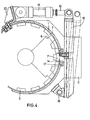
- Fig. 4 eineSchnittansicht eines Spänebrechers mit an einem Hebel befestigten Statormesser,
- Fig. 5 Schnittansicht entsprechend Fig. 2 einer abgewandelten Ausführungsform des erfindungsgemäßen Spänebrechers,
- Fig. 6 eine Ansicht nach der Schnittlinie VI-VI in Fig. 5.
- 1 is a sectional view of the new chip breaker,
- 2 is a view along the section line II-II in Fig. 1,
- 3 is a view along the section line III-III in Fig. 2,
- 4 is a sectional view of a chip breaker with a stator knife attached to a lever,
- 5 a sectional view corresponding to FIG. 2 of a modified embodiment of the chip breaker according to the invention,
- 6 is a view along the section line VI-VI in Fig. 5th
Der Spänebrecher nach Fig. 1 weist ein Prechergehäuse 1 auf, in dem ein Rotor 2 antreibbar gelagert ist. Der Rotor 2 weist einen Vorbrecharm 3 auf mit einem Vorbrechmesser 4, dessen Brechkanten mit den Brechkanten von Brechleisten 5 zusammenwirken, die fest im Brechergehäuse 1 angeordnet sind. Ferner sind am Rotor 2 Rotormesser 6 eines Feinbrechwerkes angeordnet, deren Brechkanten mit den Brechkanten mehrerer, im Brechergehäuse 1 über den Umfang verteilt angeordneter Statormesser 7 zusammenwirken. Die zu brechenden Späne gelangen aus dem Einfülltrichter 8 in das Brechergehäuse 1. Dort werden sie vom Vorbrecharm 3 erfaßt und zwischen den Brechleisten 5 und dem darin im Abstand vorbeigleitenden Vorbrechmesser 4 gebrochen. Diese vorgebrochenen Späne gelangen dann zum Feinbrechwerk und werden von dem Rotormesser 6 und Statormesser 7 feingebrochen und gelangen über den Auslaßraum 10 und der Auslaßrutsche 11 auf ein Förderband oder in einen Kübel. Da die Achse 9 des Rotors geneigt ist, hat der Brecherraum eine tiefste Stelle. Im Bereich der untersten Mantellinie des Brechergehäuses 1 sind die dort befindlichen Statormesser 71 radial beweglich angeordnet. Die Statormesser 7' sind an einem Block 14 befestigt, an dem eine Kolbenstange 16 einer hydraulischen Kolben-Zylinder-Einheit 15 angreift.The chip crusher according to FIG. 1 has a
Wie Fig. 2 zeigt, ist der Block 14 konisch ausgebildet und wird in eine entsprechend konische Führung 17 gedrückt, die auf das Brechergehäuse 1 aufgesetzt ist und die die Scherkräfte aufnimmt, welche auf die Statormesser 7' einwirken. In dieser, in Fig. 2 dargestellten Arbeitsstellung werden die Statormesser 7' mittels der Kolben-Zylinder-Einheit 15 hydraulisch blockiert. Falls ein Grobteil eine Blockade des Rotors verursacht, kann dieses Grobteil durch öffnen des Grobteilauslasses und reversierendem Antrieb des Rotors aus dem Brecherraum entfernt werden. Das Grobteil gelangt über den Grobteilauslaß 10' auf die Auslaßrutsche 11. Canach werden die Statormesser 7' wieder in ihre Arbeitsstellung gedrückt und der Spänebrecher kann seinen normalen Betrieb wieder aufnehmen. Der Rotor rotiert beispielsweise mit einer Drehzahl von 60 bis 80 U/min. Wenn der Rotor blockiert wird, ist der Rotorantrieb so gesteuert, daß er drei bis viermal reversiert. Sofern dann der Rotor sich noch nicht freigearbeitet hat, wird dem Kolben-Zylinder-Antrieb 15 ein Impuls gegeben, den Grobteilauslaß 10' durch Zurückziehen der radial beweglichen Statormesser 7' zu öffnen. Danach wird der Rotor mit einer Drehzahl von beispielswiese 2 bis 4 U/min reversierend angetrieben. Es hat sich gezeigt, daß in den meisten Fällen sich dadurch das die Blockierung bewirkende Grobteil zum geöffneten Grobteilauslaß 10' bewegt und den Brecherraum verläßt.2 shows, the
Sollte sich trotz geöffnetem Grobteilauslasses und trotz zwei oder dreimaligem Drehrichtungswechsel des Rotors der Rotor noch nicht freigearbeitet haben, muß der Spänebrecher abgeschaltet und der Deckel 12 zum Brecherraum hin geöffnet werden.If, despite the large part outlet being opened and despite two or three changes in the direction of rotation of the rotor, the rotor has not yet cleared, the chip crusher must be switched off and the
Zweckmäßigerweise sind an diesem Spänebrecher Signalgeber angebracht, die ein optisches und akustisches Signal geben, wenn nach öffnen des Grobteilauslasses 10' und nach mehrmaligem Reversieren des Motors der Rotor sich noch nicht freigearbeitet hat.Expediently, signal generators are attached to this chip breaker, which give an optical and acoustic signal when, after opening the coarse part outlet 10 'and after the motor has been reversed several times, the rotor has not yet cleared itself.
Wenn das Signal ertönt, schaltet sich der Motor ab. Nach Lösen des Deckelverschlusses kann über einen Handgriff der Gehäusedeckel 12 geöffnet werden und der Brecherraum von Hand ausgeräumt werden.When the signal sounds, the engine switches off. After loosening the cover lock, the
Der Rotor 2 ist an einer Rotorwelle befestigt, die über ein Gleitlager und ein Wälzkörperlager in einem Gestell 13 gelagert ist. Zwischen dem Brechergehäuse 1 und dem Gestell 13 ist die Auslaßrutsche 11 angeordnet. An der Unterseite des Rotors ist ein mitrotierender Wischer 30 angeordnet, der die zerbrochenen Späne aus dem Auslaßraum 10 herausschiebt, damit sie auf die Auslaßrutsche 11 gelangen.The
Bei dem Ausführungsbeispiel nach Fig. 4 ist nur ein Statormesser 7' radial beweglich angeordnet. Dieses Statormesser 7' ist über einen Block 14 an einem steifen Hebel 18 befestigt, der um dieAchse 19 schwenkbar am Brechergehäuse 1 gelagert ist und der von einem Kolben-Zylinder-Antrieb 15 über die Kolbenstange 16 in eine öffnungsstellung und in eine Schließstellung bewegt werden kann. Damit die beim Spänebrechen auf das Statormesser 7' wirkenden Scherkräfte nicht vom Lager 19 aufgenommen werden müssen, ist das Statormesser 71 und der damit verbundene Block 14 in einer Führung 17 geführt, die auf das Brechergehäuse 1 aufgesetzt ist.In the exemplary embodiment according to FIG. 4, only one stator knife 7 'is arranged to be radially movable. This stator knife 7 'is attached via a
Die Länge des Hebels 18 entspricht etwa dem Durchmesser des Spänebrechers, so daß der gegen eine Konsole 20 sich abstützende Zylinder-Kolben-Antrieb 15 an einer Seite des Spänebrechers angeordnet werden kann.The length of the
Bei der Ausführungsform nach Fig. 5 und 6 sind nicht nur die Statormesser 71 axial beweglich angeordnet, sondern auch die an diese Statormesser 71 angrenzende Wandung 24 des Brechergehäuses 1 und ein Teil 23 der Decke 22 der Auslaßmündung 21.In the embodiment according to FIGS. 5 and 6, not only the
Auf diese Weise wird der freie Querschnitt des geöffneten Grobteilauslasses 10' erheblich vergrößert.In this way, the free cross section of the opened coarse part outlet 10 'is considerably enlarged.
Der radial verschiebbare Teil 24 der Wandung des Brechergehäuses 1 sowie der verschiebbare Teil 23 der Decke 22 der Auslaßmündung 21 bilden mit Führungswänden 26 einen Schlitten 25, der radial zur Rotorachse 9 verschiebbar in einem Führungsgehäuse 27 geführt ist. In diesem Führungsgehäuse 27 befindet sich die Kolben-Zylinder-Einheit 15, deren Zylinder starr an einer Wand des Gehäuses 27 befestigt ist.The radially
- 1 Brechergehäuse1 crusher housing
- 2 Rotor2 rotor
- 3 Vorbrecharm3 pre-crushing arm
- 4 Vorbrechmesser4 primary crushing knives
- 5 Brechleiste5 crowbar
- 6 Rotormesser des Feinbrechers6 rotor knives of the fine crusher
- 7 Statormesser des Feinbrechers7 stator blades of the fine crusher
- 71 Statormesser des Feinbrechers7 1 Stator knife of the fine crusher
- 8 Einfülltrichter8 funnels
- 9 Rotorachse9 rotor axis
- 10 Auslaßraum10 outlet space
- 10' Grobteilauslaß10 'large part outlet
- 11 Auslaßrutsche11 outlet chute
- 12 Gehäusedeckel12 housing cover
- 13 Gestell13 frame
- 14 Block14 block
- 15 Zylinder-Kolben-Einheit15 cylinder-piston unit
- 16 Kolbenstange16 piston rod
- 17 Führung17 leadership
- 18 Hebel18 levers
- 19 Schwenklager19 swivel bearings
- 20 Konsole20 console
- 21 Auslaßmündung21 outlet mouth
- 22 Decke22 blanket
- 23 verschiebbarer Teil23 movable part
- 24 Teil der Gehäusewandung24 part of the housing wall
- 25 Schlitten25 sledges
- 26 Führungswände26 guide walls
- 27 Führungsgehäuse27 guide housing
Claims (7)
mindestens ein Statormesser (71) im Brechergehäuse(1) aus seiner Arbeitsstellung in eine einen Grobteilauslaß (101) freigebende öffnungsstellung radial beweglich geführt ist.1. Chip crusher with a rotor (2) arranged to be drivable in the crusher housing (1), on the inlet side of which at least one pre-breaking arm (3) is arranged, the pre-breaking knife (4) cooperating with the crusher bars (5) arranged on the crusher housing, and on the outlet side several of them the circumferentially distributed rotor knives (6) of a fine crusher are arranged, the breaking edges of which cooperate with the breaking edges of a plurality of stator knives (7) distributed over the circumference in the crusher housing (1), characterized in that
at least one stator knife (7 1 ) in the crusher housing ( 1 ) is guided in a radially movable manner from its working position into an opening position which releases a coarse part outlet (10 1 ).
Applications Claiming Priority (2)
| Application Number | Priority Date | Filing Date | Title |
|---|---|---|---|
| DE8335662U | 1983-12-13 | ||
| DE19838335662U DE8335662U1 (en) | 1983-12-13 | 1983-12-13 | CHIPBREAKER |
Publications (2)
| Publication Number | Publication Date |
|---|---|
| EP0146820A1 true EP0146820A1 (en) | 1985-07-03 |
| EP0146820B1 EP0146820B1 (en) | 1987-03-04 |
Family
ID=6759787
Family Applications (1)
| Application Number | Title | Priority Date | Filing Date |
|---|---|---|---|
| EP84114517A Expired EP0146820B1 (en) | 1983-12-13 | 1984-11-30 | Comminuter for turnings |
Country Status (4)
| Country | Link |
|---|---|
| US (1) | US4903904A (en) |
| EP (1) | EP0146820B1 (en) |
| JP (1) | JPS60209264A (en) |
| DE (2) | DE8335662U1 (en) |
Cited By (6)
| Publication number | Priority date | Publication date | Assignee | Title |
|---|---|---|---|---|
| US5224656A (en) * | 1991-08-20 | 1993-07-06 | Okawara Mfg. Co., Ltd. | Method of and apparatus for producing a granular product |
| DE4239342A1 (en) * | 1992-11-23 | 1994-05-26 | Breckner Fritz | Grinding machine for agricultural and industrial products and scrap - comprises rotating wheel with funnel-shaped round cutters and fixed shear elements in housing |
| EP0738560A1 (en) * | 1995-04-18 | 1996-10-23 | Russell Dean Dudley | Apparatus for shredding, handling and conveying scrap |
| US5631356A (en) * | 1992-04-03 | 1997-05-20 | Gist-Brocades, N.V. | Selective N-acylation of amino alcohols |
| US5769337A (en) * | 1997-01-14 | 1998-06-23 | Abilfida (Chiasso) S.A. | Waste container made of synthetic material with means of reducing the volume of said waste |
| US5785261A (en) * | 1993-09-13 | 1998-07-28 | Lanner; Klaus | Device for reducing the size of steel or metal chips |
Families Citing this family (3)
| Publication number | Priority date | Publication date | Assignee | Title |
|---|---|---|---|---|
| US7748655B2 (en) * | 2007-06-15 | 2010-07-06 | Riley Power, Inc. | Crusher block assembly for particulate size reduction system |
| CN112302119B (en) * | 2020-08-24 | 2022-04-22 | 宁波新冠联机电有限公司 | Processor capable of beating long fiber food waste |
| DE102021126898B3 (en) | 2021-10-17 | 2023-03-23 | Thomas Spyra | Shredder for crushing chips |
Citations (1)
| Publication number | Priority date | Publication date | Assignee | Title |
|---|---|---|---|---|
| DE2547980A1 (en) * | 1975-10-27 | 1977-04-28 | Richard Steimel | SPA CRUSHER |
Family Cites Families (2)
| Publication number | Priority date | Publication date | Assignee | Title |
|---|---|---|---|---|
| US3703970A (en) * | 1971-02-23 | 1972-11-28 | Benson Ind Ltd | Apparatus for treating waste material |
| JPS5823142A (en) * | 1981-07-31 | 1983-02-10 | Toshiba Corp | Manufacture of cathode structure |
-
1983
- 1983-12-13 DE DE19838335662U patent/DE8335662U1/en not_active Expired
-
1984
- 1984-11-30 EP EP84114517A patent/EP0146820B1/en not_active Expired
- 1984-11-30 DE DE8484114517T patent/DE3462437D1/en not_active Expired
- 1984-12-12 JP JP59260988A patent/JPS60209264A/en active Pending
-
1989
- 1989-05-15 US US07/352,130 patent/US4903904A/en not_active Expired - Fee Related
Patent Citations (1)
| Publication number | Priority date | Publication date | Assignee | Title |
|---|---|---|---|---|
| DE2547980A1 (en) * | 1975-10-27 | 1977-04-28 | Richard Steimel | SPA CRUSHER |
Cited By (6)
| Publication number | Priority date | Publication date | Assignee | Title |
|---|---|---|---|---|
| US5224656A (en) * | 1991-08-20 | 1993-07-06 | Okawara Mfg. Co., Ltd. | Method of and apparatus for producing a granular product |
| US5631356A (en) * | 1992-04-03 | 1997-05-20 | Gist-Brocades, N.V. | Selective N-acylation of amino alcohols |
| DE4239342A1 (en) * | 1992-11-23 | 1994-05-26 | Breckner Fritz | Grinding machine for agricultural and industrial products and scrap - comprises rotating wheel with funnel-shaped round cutters and fixed shear elements in housing |
| US5785261A (en) * | 1993-09-13 | 1998-07-28 | Lanner; Klaus | Device for reducing the size of steel or metal chips |
| EP0738560A1 (en) * | 1995-04-18 | 1996-10-23 | Russell Dean Dudley | Apparatus for shredding, handling and conveying scrap |
| US5769337A (en) * | 1997-01-14 | 1998-06-23 | Abilfida (Chiasso) S.A. | Waste container made of synthetic material with means of reducing the volume of said waste |
Also Published As
| Publication number | Publication date |
|---|---|
| EP0146820B1 (en) | 1987-03-04 |
| JPS60209264A (en) | 1985-10-21 |
| DE8335662U1 (en) | 1984-03-08 |
| US4903904A (en) | 1990-02-27 |
| DE3462437D1 (en) | 1987-04-09 |
Similar Documents
| Publication | Publication Date | Title |
|---|---|---|
| DE2047006C3 (en) | Plant for shredding and partial separation of garbage | |
| EP1287878B1 (en) | Apparatus fot treatment of materials | |
| EP1255612B1 (en) | Method and device for reducing cuttings | |
| EP0346661A2 (en) | Chopping and shredding machine | |
| EP0146820B1 (en) | Comminuter for turnings | |
| EP1071343B1 (en) | Device for crushing fruit | |
| DE2547980C2 (en) | ||
| DE102008039258A1 (en) | crusher | |
| DE3704300A1 (en) | HAMMER CRUSHER TO BREAK HARD AND SOFT MATERIALS | |
| DE4328506C1 (en) | Chip breaker | |
| DE4026795A1 (en) | Machine for cutting up pieces of scrap wood - has slowly rotating rotor which cooperates with two fixed blades | |
| DE4423150C1 (en) | Pump for waste water system | |
| DE3431658C1 (en) | Formation of the working gap in a shredding machine with a horizontally arranged hammer breaker rotor | |
| DE2026479C3 (en) | Continuously working centrifuge | |
| AT520985B1 (en) | crushing device | |
| DE102011007960B3 (en) | Pump for use with machine tool for conveying metal shavings contaminated coolant, has cutting mechanism comprising cutting body, and wear plate provided in pump housing, where cutting plate is detachably secured on cutting mechanism | |
| DE2925030C2 (en) | Device for shredding waste such as turnings or the like. | |
| DE3245373A1 (en) | Apparatus for disintegrating waste wood, in particular stumps, to form wood chips | |
| DE4400228C2 (en) | Device for opening and emptying containers | |
| EP0614700B1 (en) | Unloading disc for cutter-mixer | |
| DE1453759C (en) | Centrifugal pump, especially for collecting dirty water | |
| DE3045810C2 (en) | Device and method for controlling a wood grinder | |
| DE10306765A1 (en) | Empty beverage container crusher has housing wall of concave curved shape having radius of curvature greater than radius of crushing roller and has free edge located within working range of roller | |
| DE219227C (en) | ||
| EP0089571A2 (en) | Wood disintegrating device |
Legal Events
| Date | Code | Title | Description |
|---|---|---|---|
| PUAI | Public reference made under article 153(3) epc to a published international application that has entered the european phase |
Free format text: ORIGINAL CODE: 0009012 |
|
| AK | Designated contracting states |
Designated state(s): DE FR GB IT |
|
| 17P | Request for examination filed |
Effective date: 19851204 |
|
| 17Q | First examination report despatched |
Effective date: 19860610 |
|
| GRAA | (expected) grant |
Free format text: ORIGINAL CODE: 0009210 |
|
| AK | Designated contracting states |
Kind code of ref document: B1 Designated state(s): DE FR GB IT |
|
| ITF | It: translation for a ep patent filed |
Owner name: ING. C. GREGORJ S.P.A. |
|
| REF | Corresponds to: |
Ref document number: 3462437 Country of ref document: DE Date of ref document: 19870409 |
|
| ET | Fr: translation filed | ||
| PLBE | No opposition filed within time limit |
Free format text: ORIGINAL CODE: 0009261 |
|
| STAA | Information on the status of an ep patent application or granted ep patent |
Free format text: STATUS: NO OPPOSITION FILED WITHIN TIME LIMIT |
|
| 26N | No opposition filed | ||
| ITTA | It: last paid annual fee | ||
| PGFP | Annual fee paid to national office [announced via postgrant information from national office to epo] |
Ref country code: FR Payment date: 19951017 Year of fee payment: 12 |
|
| PGFP | Annual fee paid to national office [announced via postgrant information from national office to epo] |
Ref country code: GB Payment date: 19951113 Year of fee payment: 12 |
|
| PGFP | Annual fee paid to national office [announced via postgrant information from national office to epo] |
Ref country code: DE Payment date: 19960123 Year of fee payment: 12 |
|
| PG25 | Lapsed in a contracting state [announced via postgrant information from national office to epo] |
Ref country code: GB Effective date: 19961130 |
|
| GBPC | Gb: european patent ceased through non-payment of renewal fee |
Effective date: 19961130 |
|
| PG25 | Lapsed in a contracting state [announced via postgrant information from national office to epo] |
Ref country code: FR Effective date: 19970731 |
|
| PG25 | Lapsed in a contracting state [announced via postgrant information from national office to epo] |
Ref country code: DE Effective date: 19970801 |
|
| REG | Reference to a national code |
Ref country code: FR Ref legal event code: ST |