EP0146788B1 - Apparatus for coating steel objects with an alloy of zinc and aluminium - Google Patents
Apparatus for coating steel objects with an alloy of zinc and aluminium Download PDFInfo
- Publication number
- EP0146788B1 EP0146788B1 EP84114110A EP84114110A EP0146788B1 EP 0146788 B1 EP0146788 B1 EP 0146788B1 EP 84114110 A EP84114110 A EP 84114110A EP 84114110 A EP84114110 A EP 84114110A EP 0146788 B1 EP0146788 B1 EP 0146788B1
- Authority
- EP
- European Patent Office
- Prior art keywords
- steel objects
- cage means
- bath
- cage
- tray
- Prior art date
- Legal status (The legal status is an assumption and is not a legal conclusion. Google has not performed a legal analysis and makes no representation as to the accuracy of the status listed.)
- Expired
Links
- 229910000831 Steel Inorganic materials 0.000 title claims abstract description 41
- 239000010959 steel Substances 0.000 title claims abstract description 41
- 238000000576 coating method Methods 0.000 title claims abstract description 17
- 239000004411 aluminium Substances 0.000 title claims abstract description 15
- XAGFODPZIPBFFR-UHFFFAOYSA-N aluminium Chemical compound [Al] XAGFODPZIPBFFR-UHFFFAOYSA-N 0.000 title claims abstract description 15
- 239000011248 coating agent Substances 0.000 title claims abstract description 15
- 229910001297 Zn alloy Inorganic materials 0.000 title claims abstract description 10
- 229910000838 Al alloy Inorganic materials 0.000 title claims abstract description 5
- 229910052782 aluminium Inorganic materials 0.000 claims abstract description 10
- 230000001681 protective effect Effects 0.000 claims abstract description 8
- 229910045601 alloy Inorganic materials 0.000 claims description 8
- 239000000956 alloy Substances 0.000 claims description 8
- 238000010438 heat treatment Methods 0.000 claims description 4
- 239000012535 impurity Substances 0.000 claims description 3
- 238000000034 method Methods 0.000 claims description 3
- 238000001816 cooling Methods 0.000 claims 1
- 239000000463 material Substances 0.000 claims 1
- HCHKCACWOHOZIP-UHFFFAOYSA-N Zinc Chemical compound [Zn] HCHKCACWOHOZIP-UHFFFAOYSA-N 0.000 abstract description 18
- 239000011701 zinc Substances 0.000 abstract description 18
- 229910052725 zinc Inorganic materials 0.000 abstract description 18
- PNEYBMLMFCGWSK-UHFFFAOYSA-N Alumina Chemical compound [O-2].[O-2].[O-2].[Al+3].[Al+3] PNEYBMLMFCGWSK-UHFFFAOYSA-N 0.000 description 3
- 238000005119 centrifugation Methods 0.000 description 3
- 239000007789 gas Substances 0.000 description 3
- IJGRMHOSHXDMSA-UHFFFAOYSA-N Atomic nitrogen Chemical compound N#N IJGRMHOSHXDMSA-UHFFFAOYSA-N 0.000 description 2
- XEEYBQQBJWHFJM-UHFFFAOYSA-N Iron Chemical compound [Fe] XEEYBQQBJWHFJM-UHFFFAOYSA-N 0.000 description 2
- 230000005540 biological transmission Effects 0.000 description 2
- 229910001873 dinitrogen Inorganic materials 0.000 description 2
- 239000006023 eutectic alloy Substances 0.000 description 2
- 230000004907 flux Effects 0.000 description 2
- 229910052751 metal Inorganic materials 0.000 description 2
- 239000002184 metal Substances 0.000 description 2
- 238000007796 conventional method Methods 0.000 description 1
- 238000005260 corrosion Methods 0.000 description 1
- 230000007797 corrosion Effects 0.000 description 1
- 230000000694 effects Effects 0.000 description 1
- 229910052742 iron Inorganic materials 0.000 description 1
- 239000000155 melt Substances 0.000 description 1
- 230000003647 oxidation Effects 0.000 description 1
- 238000007254 oxidation reaction Methods 0.000 description 1
- 230000001590 oxidative effect Effects 0.000 description 1
- 239000002893 slag Substances 0.000 description 1
- 230000008023 solidification Effects 0.000 description 1
- 238000007711 solidification Methods 0.000 description 1
Images


Classifications
-
- C—CHEMISTRY; METALLURGY
- C23—COATING METALLIC MATERIAL; COATING MATERIAL WITH METALLIC MATERIAL; CHEMICAL SURFACE TREATMENT; DIFFUSION TREATMENT OF METALLIC MATERIAL; COATING BY VACUUM EVAPORATION, BY SPUTTERING, BY ION IMPLANTATION OR BY CHEMICAL VAPOUR DEPOSITION, IN GENERAL; INHIBITING CORROSION OF METALLIC MATERIAL OR INCRUSTATION IN GENERAL
- C23C—COATING METALLIC MATERIAL; COATING MATERIAL WITH METALLIC MATERIAL; SURFACE TREATMENT OF METALLIC MATERIAL BY DIFFUSION INTO THE SURFACE, BY CHEMICAL CONVERSION OR SUBSTITUTION; COATING BY VACUUM EVAPORATION, BY SPUTTERING, BY ION IMPLANTATION OR BY CHEMICAL VAPOUR DEPOSITION, IN GENERAL
- C23C2/00—Hot-dipping or immersion processes for applying the coating material in the molten state without affecting the shape; Apparatus therefor
- C23C2/14—Removing excess of molten coatings; Controlling or regulating the coating thickness
-
- C—CHEMISTRY; METALLURGY
- C23—COATING METALLIC MATERIAL; COATING MATERIAL WITH METALLIC MATERIAL; CHEMICAL SURFACE TREATMENT; DIFFUSION TREATMENT OF METALLIC MATERIAL; COATING BY VACUUM EVAPORATION, BY SPUTTERING, BY ION IMPLANTATION OR BY CHEMICAL VAPOUR DEPOSITION, IN GENERAL; INHIBITING CORROSION OF METALLIC MATERIAL OR INCRUSTATION IN GENERAL
- C23C—COATING METALLIC MATERIAL; COATING MATERIAL WITH METALLIC MATERIAL; SURFACE TREATMENT OF METALLIC MATERIAL BY DIFFUSION INTO THE SURFACE, BY CHEMICAL CONVERSION OR SUBSTITUTION; COATING BY VACUUM EVAPORATION, BY SPUTTERING, BY ION IMPLANTATION OR BY CHEMICAL VAPOUR DEPOSITION, IN GENERAL
- C23C2/00—Hot-dipping or immersion processes for applying the coating material in the molten state without affecting the shape; Apparatus therefor
- C23C2/04—Hot-dipping or immersion processes for applying the coating material in the molten state without affecting the shape; Apparatus therefor characterised by the coating material
- C23C2/06—Zinc or cadmium or alloys based thereon
-
- C—CHEMISTRY; METALLURGY
- C23—COATING METALLIC MATERIAL; COATING MATERIAL WITH METALLIC MATERIAL; CHEMICAL SURFACE TREATMENT; DIFFUSION TREATMENT OF METALLIC MATERIAL; COATING BY VACUUM EVAPORATION, BY SPUTTERING, BY ION IMPLANTATION OR BY CHEMICAL VAPOUR DEPOSITION, IN GENERAL; INHIBITING CORROSION OF METALLIC MATERIAL OR INCRUSTATION IN GENERAL
- C23C—COATING METALLIC MATERIAL; COATING MATERIAL WITH METALLIC MATERIAL; SURFACE TREATMENT OF METALLIC MATERIAL BY DIFFUSION INTO THE SURFACE, BY CHEMICAL CONVERSION OR SUBSTITUTION; COATING BY VACUUM EVAPORATION, BY SPUTTERING, BY ION IMPLANTATION OR BY CHEMICAL VAPOUR DEPOSITION, IN GENERAL
- C23C2/00—Hot-dipping or immersion processes for applying the coating material in the molten state without affecting the shape; Apparatus therefor
- C23C2/02—Pretreatment of the material to be coated, e.g. for coating on selected surface areas
- C23C2/022—Pretreatment of the material to be coated, e.g. for coating on selected surface areas by heating
- C23C2/0222—Pretreatment of the material to be coated, e.g. for coating on selected surface areas by heating in a reactive atmosphere, e.g. oxidising or reducing atmosphere
Abstract
Description
- From the zinc coating of thin steel sheets it is known that a coating comprising an eutectic alloy of zinc and 5% aluminium is two to three times more durable in corrosion protection than a conventional zinc or iron/zinc coating.
- However, small steel products, such as bolts, cannot be coated with this zinc alloy by means of a conventional flux-based dip zinc coating method, because the flux reacts with the aluminium contained in the zinc, which results in a poor quality and adhesion of the coating. Further, in a conventional zinc coating method the excess zinc melt is removed, for example, form the threads of bolts by means of a centrifuge in an oxidizing atmosphere. When centrifuging the alloy of zinc and 5% aluminium, molten aluminium is rapidly oxidized while producing an aluminium oxide film on the melt surface, which prevents a uniform removal of excess molten metal from beneath the film.
- According to the present invention, the steel objects to be coated are preheated to a temperature within the range 400°C-950°C in a furnace containing a protective, reducing gas and are introduced in a zinc bath containing at least approximately 5% of aluminium, into a cage which after a predetermined time is lifted out of the bath into a centrifuging chamber containing an oxygen-free atmosphere, such as nitrogen gas.
- The present invention provides an apparatus by means of which small steel objects conveniently can be zinc-coated in the above summarized manner, when the temperature of the zinc bath is in the range 390°C to 430°C.
- The apparatus according to the invention comprises means for pre-heating the steel objects, a reservoir containing a bath of molten alloyofzinc and aluminium, a chute for feeding the steel objects from the preheating means to a cage means,
- a centrifuging chamber above the bath,
- said cage means being movably arranged between a first position within the bath to receive the steel objects fed into the bath, and a second position in the centrifuging chamber above the bath in which the cage means is arranged to rotate in order to remove excess coating alloy from the steel objects, a guiding pipe arranged between the protective chute and the cage means to lead the steel objects into the cage means, means provided to produce a flow of molten alloy in the guiding pipe in the same direction as the steel objects move through the guiding pipe, and
- means for removing the steel objects from the cage means to the outside of the centrifuging chamber.
- Preferred embodiments of the apparatus will appear from the following detailed description where reference is made to the accompanying schematical drawing, as well as from the subclaims.
- Further, the invention relates to a process for coating steel objects with an alloy of zinc and aluminium as recited in
claims - Figure 1 illustrates the step of introducing the steel objects into the cage immersed in the zinc bath.
- Figure 2 is a section taken along line A,-A2 in Figure 1.
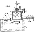
- Figure 3 illustrates the centrifuging step.
- Figure 4 illustrates the step of removing the coated objects from the centrifuging chamber.
- In the drawing,
reference numeral 1 designates a reservoirfora azinc bath 2 containing preferably 5% of aluminium, at least approximately. The temperature of the bath is preferably within the range 390°C to 430°C. - The steel objects to be coated are indicated by short, thick arrows and are, before being fed into the bath, preheated to a temperature within the range 400°C to 950°C in a furnace containing a protective, reducing atmosphere. The furnace arrangement is not shown in the drawing since it is such is earlier known, as one example US Patent Specification No. 4,170,495 can be mentioned.
- As illustrated in Figure 1, the objects to be coated enter the
bath 2 through aprotective chute 3 which together with a receiving guidingpipe 4 forms a gas tight seal at the bath surface. The supports ofpipe 4 are schematically indicated at 5. The objects proceed throughpipe 4 conveyed by means of a molten metal flow indicated by longer narrow arrows and produced by schematically shownpump 11 to a perforatedcentrifuging cage 6. The steel objects are prevented from leaving thecentrifuging cage 6 by means of aguide ring 7 integral with the guidingpipe 4 and by means of a cover 8 of the centrifuging cage. The centrifuging cage rotates all the time, at a speed of e.g. 20-60 r.p.m., by means of amotor 13, through a chain orbelt transmission 14, aclutch shaft 12, while permitting a uniform placement of the steel objects on theconical bottom 10 of thecage 6. The time the cage stays in the bath can be adjusted steplessly, by the use of arrangement well known and therefore not further described here. - The adjustment of the thickness of the zinc coating takes place, as in a conventional method, by means of centrifuging, as shown in Figure 3. Above the zinc bath is mounted a
centrifuging chamber 17 which through awall protrusion 18 forms a tight gas seal and is filled with nitrogen gas which prevents the oxidation of the aluminium in the eutectic alloy during centrifugation and thus improves the centrifuging result. Thecentrifuging cage 6 is lifted up by means of e.g. a hydraulic cylinder not shown, into a firmcentrifuging support 20 which has a clutch means 21 engaging corresponding clutch means 9 on top of the cage cover 8 and is rotated in cycles of about 10 seconds in a reciprocating manner, at a speed of e.g. 200-500 r.p.m., by anelectric motor 23 the rotary speed of which is steplessly adjustable, over e.g. a chain orbelt transmission 24. The centrifuging efficiency depends on the rotary speed of the centrifuge, and a desired coating thickness can be achieved by adjusting the rotary speed. Thecentrifuging chamber 17 can, when required, be heated by means ofelectric resistances 22 so that a too early solidification of the molten zinc alloy can be eliminated. Surplus molten zinc hurled on thewalls 19 of the chamber due to the centrifugation flows back into the zinc bath. - After centrifugation, the steel objects are discharged, according to Figure 4, onto a
tray 28 pushed in from the side of the centrifuging chamber by a cylinder the piston rod of which is designated 30. At the same time, afront plate 29 of the tray cleans the surface of the zinc bath of any impurities (surface slag). Hereafter thecylinder 23 pushes thebottom cone 10 of thecentrifuging cage 4 down, by arod 32 telescopical with theshaft 12, thereby dropping the steel objects onto thetray 12. Thebottom cone 10 is lifted up again and thetray 28 is returned back to adischarge chamber 25. Hereafter the centrifuged steel objects are discharged from thetray 28 by means of a transfer plate orrake 26 operated by a working cylinder the piston rod of which is designated 27. - The
cage 6 is again lowered into the bath and receives a new bath of articles to be coated. The cover 8 of thecage 6 axially releasable from the cage and stops on top of theannular plate 7. In the position of Figures 3 and 4 the cover 8 of thecage 6 is of course not rotatable with respect to thesupport 20, although no specific means to this effect are shown in the drawing, the arrangement of such means will not present difficulties for a person skilled in the art.
Claims (13)
Priority Applications (1)
| Application Number | Priority Date | Filing Date | Title |
|---|---|---|---|
| AT84114110T ATE41954T1 (en) | 1983-11-29 | 1984-11-23 | DEVICE FOR PRODUCTION OF COATINGS OF TIN-ALUMINUM ALLOYS ON STEEL PARTS. |
Applications Claiming Priority (2)
| Application Number | Priority Date | Filing Date | Title |
|---|---|---|---|
| US06/556,019 US4526127A (en) | 1983-11-29 | 1983-11-29 | Apparatus for coating steel objects with an alloy of zinc and aluminium |
| US556019 | 1983-11-29 |
Publications (3)
| Publication Number | Publication Date |
|---|---|
| EP0146788A2 EP0146788A2 (en) | 1985-07-03 |
| EP0146788A3 EP0146788A3 (en) | 1985-08-21 |
| EP0146788B1 true EP0146788B1 (en) | 1989-04-05 |
Family
ID=24219546
Family Applications (1)
| Application Number | Title | Priority Date | Filing Date |
|---|---|---|---|
| EP84114110A Expired EP0146788B1 (en) | 1983-11-29 | 1984-11-23 | Apparatus for coating steel objects with an alloy of zinc and aluminium |
Country Status (9)
| Country | Link |
|---|---|
| US (1) | US4526127A (en) |
| EP (1) | EP0146788B1 (en) |
| JP (1) | JPS60155659A (en) |
| KR (1) | KR920001273B1 (en) |
| AT (1) | ATE41954T1 (en) |
| AU (1) | AU575600B2 (en) |
| CA (1) | CA1229724A (en) |
| DE (1) | DE3477586D1 (en) |
| FI (1) | FI77267C (en) |
Families Citing this family (10)
| Publication number | Priority date | Publication date | Assignee | Title |
|---|---|---|---|---|
| US4724795A (en) * | 1985-06-03 | 1988-02-16 | Acheson Industries, Inc. | Automatic solution concentration monitoring system |
| SE8503651L (en) * | 1985-07-31 | 1987-02-01 | Defab Int Ab | CONTAINER FOR SURFACE TREATMENT LIKE HEAT ZINCING OF GOODS |
| AU594844B2 (en) * | 1986-12-12 | 1990-03-15 | Jeffrey Dudley Jones | Surface treatment of articles |
| DE3823981A1 (en) * | 1987-09-10 | 1989-03-23 | Rolf Mintert | Galvanising unit for small components |
| US4847815A (en) * | 1987-09-22 | 1989-07-11 | Anadrill, Inc. | Sinusoidal pressure pulse generator for measurement while drilling tool |
| DE4016172C1 (en) * | 1990-05-19 | 1991-03-28 | Werner 5900 Siegen De Ackermann | |
| US5173334A (en) * | 1991-06-12 | 1992-12-22 | Pierre Lavaux | Apparatus and method for improved hot dip metallic coating of metal objects |
| EP2198067A4 (en) * | 2007-09-10 | 2011-10-05 | Pertti J Sippola | Method and apparatus for improved formability of galvanized steel having high tensile strength |
| WO2013162978A1 (en) * | 2012-04-23 | 2013-10-31 | Ni Industries, Inc. | A METHOD FOR PRODUCING TiAL3, AND AL-TiAL3, Ti-TiAL3 COMPOSITES |
| CN112226716B (en) * | 2020-09-09 | 2023-01-17 | 余姚市永林机械科技有限公司 | Hot galvanizing suspension device |
Family Cites Families (11)
| Publication number | Priority date | Publication date | Assignee | Title |
|---|---|---|---|---|
| DE443429C (en) * | 1927-04-30 | Albert Knepper | Device for the production of coatings, especially metallic ones, on small objects | |
| US1418412A (en) * | 1918-04-24 | 1922-06-06 | Agnes B Watrous Being | Method of metal coating and apparatus therefor |
| US1961301A (en) * | 1930-05-17 | 1934-06-05 | Nier Bruno | Apparatus for coating objects with a liquid |
| US2369592A (en) * | 1943-04-03 | 1945-02-13 | Marinsky Davis | Method of treating bobbins |
| CH272272A (en) * | 1949-06-08 | 1950-12-15 | Fischer Ag Georg | Centrifugal centrifugal device for throwing off the excess coating metal applied to metal objects by a dipping process. |
| GB777353A (en) * | 1954-07-01 | 1957-06-19 | Armco Int Corp | Finishing machine and method for use in the hot dip metallic coating of steel strip,and coated strip produced thereby |
| DE1063436B (en) * | 1958-02-25 | 1959-08-13 | Elmasch Bau Sachsenwerk Veb | Device for the production of melt coatings, in particular made of metal, on small parts in the dipping process |
| NL6513832A (en) * | 1964-10-28 | 1966-04-29 | ||
| GB1433019A (en) * | 1973-06-26 | 1976-04-22 | Turner Lisle Ltd | Galvanizing plant |
| DE2707921C3 (en) * | 1977-02-24 | 1980-12-11 | Albert Prof. Dr.-Ing. Cebulj | Method and device for removing excess metal from dip-metallized objects |
| FR2477577A1 (en) * | 1980-03-10 | 1981-09-11 | Ballin Evelyne | Hot dip zinc coating of small iron and steel parts - which are kept at high temp. after leaving zinc bath to permit diffusion of zinc |
-
1983
- 1983-11-29 US US06/556,019 patent/US4526127A/en not_active Expired - Lifetime
-
1984
- 1984-11-22 FI FI844591A patent/FI77267C/en not_active IP Right Cessation
- 1984-11-22 AU AU35782/84A patent/AU575600B2/en not_active Ceased
- 1984-11-23 EP EP84114110A patent/EP0146788B1/en not_active Expired
- 1984-11-23 AT AT84114110T patent/ATE41954T1/en not_active IP Right Cessation
- 1984-11-23 DE DE8484114110T patent/DE3477586D1/en not_active Expired
- 1984-11-28 CA CA000468788A patent/CA1229724A/en not_active Expired
- 1984-11-28 KR KR1019840007460A patent/KR920001273B1/en not_active IP Right Cessation
- 1984-11-29 JP JP59250647A patent/JPS60155659A/en active Pending
Also Published As
| Publication number | Publication date |
|---|---|
| KR920001273B1 (en) | 1992-02-10 |
| US4526127A (en) | 1985-07-02 |
| EP0146788A2 (en) | 1985-07-03 |
| ATE41954T1 (en) | 1989-04-15 |
| AU575600B2 (en) | 1988-08-04 |
| FI77267C (en) | 1989-02-10 |
| AU3578284A (en) | 1985-06-06 |
| FI77267B (en) | 1988-10-31 |
| DE3477586D1 (en) | 1989-05-11 |
| JPS60155659A (en) | 1985-08-15 |
| EP0146788A3 (en) | 1985-08-21 |
| CA1229724A (en) | 1987-12-01 |
| FI844591A0 (en) | 1984-11-22 |
| FI844591L (en) | 1985-05-30 |
| KR850005001A (en) | 1985-08-19 |
Similar Documents
| Publication | Publication Date | Title |
|---|---|---|
| EP0146788B1 (en) | Apparatus for coating steel objects with an alloy of zinc and aluminium | |
| DE4016172C1 (en) | ||
| EP0745694B1 (en) | Method and apparatus for shaping semisolid metals | |
| EP2527476B1 (en) | Flexible minimum energy utlilisation electric arc furnace system and processes for making steel products. | |
| CA2360306A1 (en) | Continuous charge preheating, melting, refining and casting | |
| CN214300303U (en) | Brazing filler metal surface hot dip tinning device | |
| DE3767262D1 (en) | PLANT FOR PRODUCING SEMI-FINISHED PRODUCTS FROM A BATCH OF METAL, AND AN APPROPRIATE MELTING AND CASTING METHOD. | |
| US3247555A (en) | Aluminum melting furnace | |
| JP4291995B2 (en) | Warm sizing equipment for ferrous sintered alloy parts | |
| KR100221703B1 (en) | Method for manufacturing copper covered steel wire | |
| US4150971A (en) | Start-up method for an electroslag remelting system | |
| EP0030441A1 (en) | Apparatus for and method of feeding molten metal at a controlled rate | |
| RU2032762C1 (en) | Apparatus for the application of coating on the inner surface of pipes | |
| US305442A (en) | Apparatus for coating pipes | |
| EP0450070A1 (en) | Method of continuously plating metal plates | |
| US1191435A (en) | Process for the electric melting of metals. | |
| CN1173069C (en) | Coating metal strip | |
| JP3111035B2 (en) | Continuous metal strip coating pot | |
| JPH06330203A (en) | Method for charging material to vacuum induction melting furnace for al-li alloy | |
| US1110208A (en) | Process of electrically treating, melting, and refining metals. | |
| SU831855A1 (en) | Device for hot zinc-plating | |
| EP0339790A1 (en) | Application of bearing alloy to bearing surfaces | |
| JPS6342128Y2 (en) | ||
| JPH01142016A (en) | Continuous vacuum degassing apparatus for molten copper | |
| JPH06218532A (en) | Automatic continuous melting/casting apparatus |
Legal Events
| Date | Code | Title | Description |
|---|---|---|---|
| PUAI | Public reference made under article 153(3) epc to a published international application that has entered the european phase |
Free format text: ORIGINAL CODE: 0009012 |
|
| PUAL | Search report despatched |
Free format text: ORIGINAL CODE: 0009013 |
|
| AK | Designated contracting states |
Designated state(s): AT CH DE FR GB LI NL SE |
|
| AK | Designated contracting states |
Designated state(s): AT CH DE FR GB LI NL SE |
|
| 17P | Request for examination filed |
Effective date: 19860215 |
|
| 17Q | First examination report despatched |
Effective date: 19870714 |
|
| RAP1 | Party data changed (applicant data changed or rights of an application transferred) |
Owner name: RASMET KY |
|
| GRAA | (expected) grant |
Free format text: ORIGINAL CODE: 0009210 |
|
| AK | Designated contracting states |
Kind code of ref document: B1 Designated state(s): AT CH DE FR GB LI NL SE |
|
| REF | Corresponds to: |
Ref document number: 41954 Country of ref document: AT Date of ref document: 19890415 Kind code of ref document: T |
|
| REF | Corresponds to: |
Ref document number: 3477586 Country of ref document: DE Date of ref document: 19890511 |
|
| ET | Fr: translation filed | ||
| PLBE | No opposition filed within time limit |
Free format text: ORIGINAL CODE: 0009261 |
|
| STAA | Information on the status of an ep patent application or granted ep patent |
Free format text: STATUS: NO OPPOSITION FILED WITHIN TIME LIMIT |
|
| 26N | No opposition filed | ||
| EAL | Se: european patent in force in sweden |
Ref document number: 84114110.4 |
|
| PGFP | Annual fee paid to national office [announced via postgrant information from national office to epo] |
Ref country code: AT Payment date: 19990512 Year of fee payment: 15 |
|
| PGFP | Annual fee paid to national office [announced via postgrant information from national office to epo] |
Ref country code: GB Payment date: 19990514 Year of fee payment: 15 |
|
| PGFP | Annual fee paid to national office [announced via postgrant information from national office to epo] |
Ref country code: FR Payment date: 19990519 Year of fee payment: 15 |
|
| PGFP | Annual fee paid to national office [announced via postgrant information from national office to epo] |
Ref country code: CH Payment date: 19990528 Year of fee payment: 15 |
|
| PGFP | Annual fee paid to national office [announced via postgrant information from national office to epo] |
Ref country code: SE Payment date: 19990531 Year of fee payment: 15 Ref country code: NL Payment date: 19990531 Year of fee payment: 15 |
|
| PG25 | Lapsed in a contracting state [announced via postgrant information from national office to epo] |
Ref country code: GB Free format text: LAPSE BECAUSE OF NON-PAYMENT OF DUE FEES Effective date: 19991123 Ref country code: AT Free format text: LAPSE BECAUSE OF NON-PAYMENT OF DUE FEES Effective date: 19991123 |
|
| PG25 | Lapsed in a contracting state [announced via postgrant information from national office to epo] |
Ref country code: SE Free format text: LAPSE BECAUSE OF NON-PAYMENT OF DUE FEES Effective date: 19991124 |
|
| PG25 | Lapsed in a contracting state [announced via postgrant information from national office to epo] |
Ref country code: CH Free format text: LAPSE BECAUSE OF NON-PAYMENT OF DUE FEES Effective date: 19991130 Ref country code: LI Free format text: LAPSE BECAUSE OF NON-PAYMENT OF DUE FEES Effective date: 19991130 |
|
| PG25 | Lapsed in a contracting state [announced via postgrant information from national office to epo] |
Ref country code: NL Free format text: LAPSE BECAUSE OF NON-PAYMENT OF DUE FEES Effective date: 20000601 |
|
| PGFP | Annual fee paid to national office [announced via postgrant information from national office to epo] |
Ref country code: DE Payment date: 20000607 Year of fee payment: 16 |
|
| GBPC | Gb: european patent ceased through non-payment of renewal fee |
Effective date: 19991123 |
|
| REG | Reference to a national code |
Ref country code: CH Ref legal event code: PL |
|
| EUG | Se: european patent has lapsed |
Ref document number: 84114110.4 |
|
| PG25 | Lapsed in a contracting state [announced via postgrant information from national office to epo] |
Ref country code: FR Free format text: LAPSE BECAUSE OF NON-PAYMENT OF DUE FEES Effective date: 20000731 |
|
| NLV4 | Nl: lapsed or anulled due to non-payment of the annual fee |
Effective date: 20000601 |
|
| REG | Reference to a national code |
Ref country code: FR Ref legal event code: ST |
|
| PG25 | Lapsed in a contracting state [announced via postgrant information from national office to epo] |
Ref country code: DE Free format text: LAPSE BECAUSE OF NON-PAYMENT OF DUE FEES Effective date: 20010801 |