EP0146753B1 - Verfahren und Vorrichtung zum Befestigen von Einbauteilen in Hohlkörpern aus thermoplastischen Kunststoffen - Google Patents
Verfahren und Vorrichtung zum Befestigen von Einbauteilen in Hohlkörpern aus thermoplastischen Kunststoffen Download PDFInfo
- Publication number
- EP0146753B1 EP0146753B1 EP84113557A EP84113557A EP0146753B1 EP 0146753 B1 EP0146753 B1 EP 0146753B1 EP 84113557 A EP84113557 A EP 84113557A EP 84113557 A EP84113557 A EP 84113557A EP 0146753 B1 EP0146753 B1 EP 0146753B1
- Authority
- EP
- European Patent Office
- Prior art keywords
- anvil
- head
- built
- hollow body
- welding
- Prior art date
- Legal status (The legal status is an assumption and is not a legal conclusion. Google has not performed a legal analysis and makes no representation as to the accuracy of the status listed.)
- Expired
Links
- 238000000034 method Methods 0.000 title claims description 13
- 229920005992 thermoplastic resin Polymers 0.000 title 1
- 238000003466 welding Methods 0.000 claims description 23
- 238000007493 shaping process Methods 0.000 claims description 2
- 229920001169 thermoplastic Polymers 0.000 claims description 2
- 239000004416 thermosoftening plastic Substances 0.000 claims 1
- 239000004033 plastic Substances 0.000 description 5
- 229920003023 plastic Polymers 0.000 description 5
- 238000002604 ultrasonography Methods 0.000 description 5
- PPBRXRYQALVLMV-UHFFFAOYSA-N Styrene Chemical compound C=CC1=CC=CC=C1 PPBRXRYQALVLMV-UHFFFAOYSA-N 0.000 description 4
- 238000006073 displacement reaction Methods 0.000 description 3
- 238000009434 installation Methods 0.000 description 3
- 239000007788 liquid Substances 0.000 description 3
- 229920000642 polymer Polymers 0.000 description 3
- 238000005192 partition Methods 0.000 description 2
- -1 polyethylene Polymers 0.000 description 2
- OKTJSMMVPCPJKN-UHFFFAOYSA-N Carbon Chemical compound [C] OKTJSMMVPCPJKN-UHFFFAOYSA-N 0.000 description 1
- ZAMOUSCENKQFHK-UHFFFAOYSA-N Chlorine atom Chemical compound [Cl] ZAMOUSCENKQFHK-UHFFFAOYSA-N 0.000 description 1
- 239000004952 Polyamide Substances 0.000 description 1
- 239000004698 Polyethylene Substances 0.000 description 1
- 239000004743 Polypropylene Substances 0.000 description 1
- 239000004793 Polystyrene Substances 0.000 description 1
- 229910001069 Ti alloy Inorganic materials 0.000 description 1
- RTAQQCXQSZGOHL-UHFFFAOYSA-N Titanium Chemical compound [Ti] RTAQQCXQSZGOHL-UHFFFAOYSA-N 0.000 description 1
- 239000000654 additive Substances 0.000 description 1
- 239000002216 antistatic agent Substances 0.000 description 1
- 230000015572 biosynthetic process Effects 0.000 description 1
- 238000007664 blowing Methods 0.000 description 1
- 229910052799 carbon Inorganic materials 0.000 description 1
- 229910052801 chlorine Inorganic materials 0.000 description 1
- 239000000460 chlorine Substances 0.000 description 1
- 238000010276 construction Methods 0.000 description 1
- 238000001816 cooling Methods 0.000 description 1
- 229920001577 copolymer Polymers 0.000 description 1
- 238000002845 discoloration Methods 0.000 description 1
- 238000005516 engineering process Methods 0.000 description 1
- 239000004744 fabric Substances 0.000 description 1
- 239000000835 fiber Substances 0.000 description 1
- 239000000945 filler Substances 0.000 description 1
- 239000003063 flame retardant Substances 0.000 description 1
- 239000002828 fuel tank Substances 0.000 description 1
- 239000011521 glass Substances 0.000 description 1
- 239000000314 lubricant Substances 0.000 description 1
- 238000004519 manufacturing process Methods 0.000 description 1
- 239000000203 mixture Substances 0.000 description 1
- 239000004745 nonwoven fabric Substances 0.000 description 1
- 239000000049 pigment Substances 0.000 description 1
- 229920003229 poly(methyl methacrylate) Polymers 0.000 description 1
- 229920002647 polyamide Polymers 0.000 description 1
- 239000004417 polycarbonate Substances 0.000 description 1
- 229920000515 polycarbonate Polymers 0.000 description 1
- 229920000573 polyethylene Polymers 0.000 description 1
- 239000004926 polymethyl methacrylate Substances 0.000 description 1
- 229920000098 polyolefin Polymers 0.000 description 1
- 229920001155 polypropylene Polymers 0.000 description 1
- 229920002223 polystyrene Polymers 0.000 description 1
- 239000004800 polyvinyl chloride Substances 0.000 description 1
- 229920000915 polyvinyl chloride Polymers 0.000 description 1
- 239000003381 stabilizer Substances 0.000 description 1
- 239000000126 substance Substances 0.000 description 1
- 230000008961 swelling Effects 0.000 description 1
- 239000012815 thermoplastic material Substances 0.000 description 1
- 229910052719 titanium Inorganic materials 0.000 description 1
- 239000010936 titanium Substances 0.000 description 1
Images


Classifications
-
- B—PERFORMING OPERATIONS; TRANSPORTING
- B29—WORKING OF PLASTICS; WORKING OF SUBSTANCES IN A PLASTIC STATE IN GENERAL
- B29C—SHAPING OR JOINING OF PLASTICS; SHAPING OF MATERIAL IN A PLASTIC STATE, NOT OTHERWISE PROVIDED FOR; AFTER-TREATMENT OF THE SHAPED PRODUCTS, e.g. REPAIRING
- B29C65/00—Joining or sealing of preformed parts, e.g. welding of plastics materials; Apparatus therefor
- B29C65/78—Means for handling the parts to be joined, e.g. for making containers or hollow articles, e.g. means for handling sheets, plates, web-like materials, tubular articles, hollow articles or elements to be joined therewith; Means for discharging the joined articles from the joining apparatus
- B29C65/7802—Positioning the parts to be joined, e.g. aligning, indexing or centring
-
- B—PERFORMING OPERATIONS; TRANSPORTING
- B29—WORKING OF PLASTICS; WORKING OF SUBSTANCES IN A PLASTIC STATE IN GENERAL
- B29C—SHAPING OR JOINING OF PLASTICS; SHAPING OF MATERIAL IN A PLASTIC STATE, NOT OTHERWISE PROVIDED FOR; AFTER-TREATMENT OF THE SHAPED PRODUCTS, e.g. REPAIRING
- B29C65/00—Joining or sealing of preformed parts, e.g. welding of plastics materials; Apparatus therefor
- B29C65/02—Joining or sealing of preformed parts, e.g. welding of plastics materials; Apparatus therefor by heating, with or without pressure
- B29C65/08—Joining or sealing of preformed parts, e.g. welding of plastics materials; Apparatus therefor by heating, with or without pressure using ultrasonic vibrations
-
- B—PERFORMING OPERATIONS; TRANSPORTING
- B29—WORKING OF PLASTICS; WORKING OF SUBSTANCES IN A PLASTIC STATE IN GENERAL
- B29C—SHAPING OR JOINING OF PLASTICS; SHAPING OF MATERIAL IN A PLASTIC STATE, NOT OTHERWISE PROVIDED FOR; AFTER-TREATMENT OF THE SHAPED PRODUCTS, e.g. REPAIRING
- B29C66/00—General aspects of processes or apparatus for joining preformed parts
- B29C66/01—General aspects dealing with the joint area or with the area to be joined
- B29C66/05—Particular design of joint configurations
- B29C66/10—Particular design of joint configurations particular design of the joint cross-sections
- B29C66/11—Joint cross-sections comprising a single joint-segment, i.e. one of the parts to be joined comprising a single joint-segment in the joint cross-section
- B29C66/112—Single lapped joints
-
- B—PERFORMING OPERATIONS; TRANSPORTING
- B29—WORKING OF PLASTICS; WORKING OF SUBSTANCES IN A PLASTIC STATE IN GENERAL
- B29C—SHAPING OR JOINING OF PLASTICS; SHAPING OF MATERIAL IN A PLASTIC STATE, NOT OTHERWISE PROVIDED FOR; AFTER-TREATMENT OF THE SHAPED PRODUCTS, e.g. REPAIRING
- B29C66/00—General aspects of processes or apparatus for joining preformed parts
- B29C66/01—General aspects dealing with the joint area or with the area to be joined
- B29C66/05—Particular design of joint configurations
- B29C66/10—Particular design of joint configurations particular design of the joint cross-sections
- B29C66/13—Single flanged joints; Fin-type joints; Single hem joints; Edge joints; Interpenetrating fingered joints; Other specific particular designs of joint cross-sections not provided for in groups B29C66/11 - B29C66/12
- B29C66/131—Single flanged joints, i.e. one of the parts to be joined being rigid and flanged in the joint area
-
- B—PERFORMING OPERATIONS; TRANSPORTING
- B29—WORKING OF PLASTICS; WORKING OF SUBSTANCES IN A PLASTIC STATE IN GENERAL
- B29C—SHAPING OR JOINING OF PLASTICS; SHAPING OF MATERIAL IN A PLASTIC STATE, NOT OTHERWISE PROVIDED FOR; AFTER-TREATMENT OF THE SHAPED PRODUCTS, e.g. REPAIRING
- B29C66/00—General aspects of processes or apparatus for joining preformed parts
- B29C66/50—General aspects of joining tubular articles; General aspects of joining long products, i.e. bars or profiled elements; General aspects of joining single elements to tubular articles, hollow articles or bars; General aspects of joining several hollow-preforms to form hollow or tubular articles
- B29C66/51—Joining tubular articles, profiled elements or bars; Joining single elements to tubular articles, hollow articles or bars; Joining several hollow-preforms to form hollow or tubular articles
- B29C66/54—Joining several hollow-preforms, e.g. half-shells, to form hollow articles, e.g. for making balls, containers; Joining several hollow-preforms, e.g. half-cylinders, to form tubular articles
-
- B—PERFORMING OPERATIONS; TRANSPORTING
- B29—WORKING OF PLASTICS; WORKING OF SUBSTANCES IN A PLASTIC STATE IN GENERAL
- B29C—SHAPING OR JOINING OF PLASTICS; SHAPING OF MATERIAL IN A PLASTIC STATE, NOT OTHERWISE PROVIDED FOR; AFTER-TREATMENT OF THE SHAPED PRODUCTS, e.g. REPAIRING
- B29C66/00—General aspects of processes or apparatus for joining preformed parts
- B29C66/50—General aspects of joining tubular articles; General aspects of joining long products, i.e. bars or profiled elements; General aspects of joining single elements to tubular articles, hollow articles or bars; General aspects of joining several hollow-preforms to form hollow or tubular articles
- B29C66/51—Joining tubular articles, profiled elements or bars; Joining single elements to tubular articles, hollow articles or bars; Joining several hollow-preforms to form hollow or tubular articles
- B29C66/54—Joining several hollow-preforms, e.g. half-shells, to form hollow articles, e.g. for making balls, containers; Joining several hollow-preforms, e.g. half-cylinders, to form tubular articles
- B29C66/545—Joining several hollow-preforms, e.g. half-shells, to form hollow articles, e.g. for making balls, containers; Joining several hollow-preforms, e.g. half-cylinders, to form tubular articles one hollow-preform being placed inside the other
-
- B—PERFORMING OPERATIONS; TRANSPORTING
- B29—WORKING OF PLASTICS; WORKING OF SUBSTANCES IN A PLASTIC STATE IN GENERAL
- B29C—SHAPING OR JOINING OF PLASTICS; SHAPING OF MATERIAL IN A PLASTIC STATE, NOT OTHERWISE PROVIDED FOR; AFTER-TREATMENT OF THE SHAPED PRODUCTS, e.g. REPAIRING
- B29C66/00—General aspects of processes or apparatus for joining preformed parts
- B29C66/50—General aspects of joining tubular articles; General aspects of joining long products, i.e. bars or profiled elements; General aspects of joining single elements to tubular articles, hollow articles or bars; General aspects of joining several hollow-preforms to form hollow or tubular articles
- B29C66/61—Joining from or joining on the inside
-
- B—PERFORMING OPERATIONS; TRANSPORTING
- B29—WORKING OF PLASTICS; WORKING OF SUBSTANCES IN A PLASTIC STATE IN GENERAL
- B29C—SHAPING OR JOINING OF PLASTICS; SHAPING OF MATERIAL IN A PLASTIC STATE, NOT OTHERWISE PROVIDED FOR; AFTER-TREATMENT OF THE SHAPED PRODUCTS, e.g. REPAIRING
- B29C66/00—General aspects of processes or apparatus for joining preformed parts
- B29C66/70—General aspects of processes or apparatus for joining preformed parts characterised by the composition, physical properties or the structure of the material of the parts to be joined; Joining with non-plastics material
- B29C66/73—General aspects of processes or apparatus for joining preformed parts characterised by the composition, physical properties or the structure of the material of the parts to be joined; Joining with non-plastics material characterised by the intensive physical properties of the material of the parts to be joined, by the optical properties of the material of the parts to be joined, by the extensive physical properties of the parts to be joined, by the state of the material of the parts to be joined or by the material of the parts to be joined being a thermoplastic or a thermoset
- B29C66/739—General aspects of processes or apparatus for joining preformed parts characterised by the composition, physical properties or the structure of the material of the parts to be joined; Joining with non-plastics material characterised by the intensive physical properties of the material of the parts to be joined, by the optical properties of the material of the parts to be joined, by the extensive physical properties of the parts to be joined, by the state of the material of the parts to be joined or by the material of the parts to be joined being a thermoplastic or a thermoset characterised by the material of the parts to be joined being a thermoplastic or a thermoset
- B29C66/7392—General aspects of processes or apparatus for joining preformed parts characterised by the composition, physical properties or the structure of the material of the parts to be joined; Joining with non-plastics material characterised by the intensive physical properties of the material of the parts to be joined, by the optical properties of the material of the parts to be joined, by the extensive physical properties of the parts to be joined, by the state of the material of the parts to be joined or by the material of the parts to be joined being a thermoplastic or a thermoset characterised by the material of the parts to be joined being a thermoplastic or a thermoset characterised by the material of at least one of the parts being a thermoplastic
- B29C66/73921—General aspects of processes or apparatus for joining preformed parts characterised by the composition, physical properties or the structure of the material of the parts to be joined; Joining with non-plastics material characterised by the intensive physical properties of the material of the parts to be joined, by the optical properties of the material of the parts to be joined, by the extensive physical properties of the parts to be joined, by the state of the material of the parts to be joined or by the material of the parts to be joined being a thermoplastic or a thermoset characterised by the material of the parts to be joined being a thermoplastic or a thermoset characterised by the material of at least one of the parts being a thermoplastic characterised by the materials of both parts being thermoplastics
-
- B—PERFORMING OPERATIONS; TRANSPORTING
- B29—WORKING OF PLASTICS; WORKING OF SUBSTANCES IN A PLASTIC STATE IN GENERAL
- B29C—SHAPING OR JOINING OF PLASTICS; SHAPING OF MATERIAL IN A PLASTIC STATE, NOT OTHERWISE PROVIDED FOR; AFTER-TREATMENT OF THE SHAPED PRODUCTS, e.g. REPAIRING
- B29C66/00—General aspects of processes or apparatus for joining preformed parts
- B29C66/70—General aspects of processes or apparatus for joining preformed parts characterised by the composition, physical properties or the structure of the material of the parts to be joined; Joining with non-plastics material
- B29C66/71—General aspects of processes or apparatus for joining preformed parts characterised by the composition, physical properties or the structure of the material of the parts to be joined; Joining with non-plastics material characterised by the composition of the plastics material of the parts to be joined
-
- B—PERFORMING OPERATIONS; TRANSPORTING
- B29—WORKING OF PLASTICS; WORKING OF SUBSTANCES IN A PLASTIC STATE IN GENERAL
- B29C—SHAPING OR JOINING OF PLASTICS; SHAPING OF MATERIAL IN A PLASTIC STATE, NOT OTHERWISE PROVIDED FOR; AFTER-TREATMENT OF THE SHAPED PRODUCTS, e.g. REPAIRING
- B29C66/00—General aspects of processes or apparatus for joining preformed parts
- B29C66/80—General aspects of machine operations or constructions and parts thereof
- B29C66/83—General aspects of machine operations or constructions and parts thereof characterised by the movement of the joining or pressing tools
- B29C66/832—Reciprocating joining or pressing tools
-
- B—PERFORMING OPERATIONS; TRANSPORTING
- B29—WORKING OF PLASTICS; WORKING OF SUBSTANCES IN A PLASTIC STATE IN GENERAL
- B29L—INDEXING SCHEME ASSOCIATED WITH SUBCLASS B29C, RELATING TO PARTICULAR ARTICLES
- B29L2031/00—Other particular articles
- B29L2031/712—Containers; Packaging elements or accessories, Packages
- B29L2031/7172—Fuel tanks, jerry cans
Definitions
- the invention relates to a method for fastening built-in parts in hollow bodies made of thermoplastic materials according to the preamble of claim 1 and to an apparatus for performing the method.
- the invention is based on the object of improving the fastening of built-in parts in hollow bodies and, in particular, of allowing greater flexibility in the construction of the hollow body and the built-in parts.
- This object is basically achieved in that the built-in parts are held in the welding position by the head of a welding anvil and the welding connections are made by two or more welding sonotrodes acting from outside through different walls of the hollow body against the inner anvil.
- an installation part can be welded to a plurality of walls of a hollow body.
- a further improvement in this sense can be achieved by placing the built-in parts on the head of the welding anvil and inserting them together with the anvil into the hollow body and shifting them into the welding position.
- the built-in parts are introduced into the hollow bodies before or after the final shaping and are subjected to the action of ultrasound energy with slight pressure, a pressure of 1 to 12 bar generally being sufficient.
- Ultrasound devices with the usual sonotrodes, which can be made of titanium or titanium alloys, for example, can be used.
- the frequency range is generally between 10 and 30, preferably between 18 and 25 kHz; the amplitude range between 20 and 40, optionally between 5 and 60 ⁇ m.
- the assembly parts are welded to the hollow body walls particularly quickly, with neither preheating nor cooling times required. There is practically no discoloration in the area of the welds.
- hollow bodies and built-in parts made of practically all thermoplastically processable plastics can be welded to one another, for example hollow bodies and built-in parts made of olefin polymers, such as polyethylene or polypropylene; Styrene polymers, such as polystyrene or copolymers of styrene; Polymers containing chlorine, such as polyvinyl chloride; Polyamides, polymethyl methacrylate, polycarbonate, and mixtures of these polymers.
- olefin polymers such as polyethylene or polypropylene
- Styrene polymers such as polystyrene or copolymers of styrene
- Polymers containing chlorine such as polyvinyl chloride
- Polyamides, polymethyl methacrylate, polycarbonate, and mixtures of these polymers such as polyvinyl chloride.
- plastics can contain the usual additives, such as fillers, pigments, antistatic agents, stabilizers, flame retardants or lubricants as well as fibrous substances in the form of mats, nonwovens, felts or fabrics made of glass, carbon or plastic fibers.
- additives such as fillers, pigments, antistatic agents, stabilizers, flame retardants or lubricants as well as fibrous substances in the form of mats, nonwovens, felts or fabrics made of glass, carbon or plastic fibers.
- the device according to the invention consists of an ultrasound generator, converters, welding sonotrodes and welding anvil and is constructed in such a way that a total of two or more welding sonotrodes arranged at a distance from one another are provided, which are operatively connected to a hook-shaped welding anvil.
- the hollow body is designated by (1).
- An installation part is arranged between the top wall (2) and the bottom (3) of the hollow body.
- the built-in part is designed as an intermediate wall (4) and has two flanges (5) and (6), which are connected to the upper wall (2) and to the floor (3) by ultrasonic welding.
- the corresponding welding device essentially consists of an ultrasonic generator, converters (not shown in the drawings), welding sonotrodes (9) and (10) and a welding anvil (8).
- the anvil (8) is introduced into the interior of the hollow body (1), the head (7) of the anvil for receiving the built-in part or the intermediate wall (4) and for supporting the two flanges (5) and (6) serves.
- the head (7) thus acts as an abutment for the welding sonotrodes (9) and (10) directed against the outer walls of the hollow body.
- the hook-shaped shape of the welding anvil (8) allows it to be displaced laterally by the distance X in the direction of arrow B after it has been introduced through the opening (11), so that the intermediate wall (4) at a point on the hollow body which is not broken through the opening (11) can be supported and fastened by the head (7) of the anvil (8).
- the intermediate wall (14) according to FIGS. 3 and 4 is designed so that it is upside down (7) of the anvil (8), inserted with the anvil (8) together through the opening (11) into the interior of the hollow body and after a lateral shift by the path X into their final position (14 ') for carrying out the fastening welding can.
- the size of the displacement path X and thus the distance Z of the partition (4) or (14) from the edge of the opening (11) depends essentially on the size of the opening (11) and on the cross-section on the anvil (which is determined by the dimension Y) 8) from.
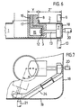
- FIG. 6 shows a piston (12) actuated by a pressure medium with a piston rod (13) to which the head (7) is attached.
- the piston (12) is guided in a cylinder (15).
- the displacement of the piston into its two end positions results in a pressure medium (liquid, gas) which is optionally directed through one of the two supply lines (16, 17) against the two working surfaces of the piston.
- the anvil (8) depending on the shape of the intermediate wall (4) relative to the hollow body (1) in addition to a lateral displacement, also perform an angular movement - angle a - (FIG. 7) and thus the fastening of an intermediate wall (24) at several points of the Allow hollow body (1). It is thus possible to connect the intermediate wall (24) not only to the top wall (2) and / or the bottom (3) of the hollow body, but also to at least one of its side walls (18, 19).
- the welding sonotrodes (10, 20, 21) show the possible connection points.
- the cross section of the intermediate wall (4, 14, 24, 34) depends on the tasks of the intermediate wall and on the position of the fastening point. While the intermediate walls (4) and (14) form a U-shaped cross section with the two flanges (5) and (6), the cross section of the intermediate wall (24) is partly U-, partly double-T-shaped.
- the intermediate wall (34) in turn has an angular cross section to which the two flanges (35) and (36) are attached.
- a built-in part designed in this way can also be inserted with the anvil into the interior of the hollow body, sitting on the head of the anvil, if, for example, a retaining lug is attached to the flange. Further embodiments of the built-in part or the partition wall depend on the respective requirements.
- the head (7) of the anvil (8) can not only be inserted into the hollow body by straight movements. If the shape of the hollow body and the built-in part permit, pivoting of the head (7) into the interior of the hollow body is particularly simple in terms of movement technology (FIG. 5).
- the direction of arrow A indicates the swivel direction.
Landscapes
- Engineering & Computer Science (AREA)
- Mechanical Engineering (AREA)
- Lining Or Joining Of Plastics Or The Like (AREA)
Description
- Die Erfindung bezieht sich auf ein Verfahren zum Befestigen von Einbauteilen in Hohlkörpern aus thermoplastischen Kunststoffen nach dem Oberbegriff des Patentanspruchs 1 sowie auf eine Vorrichtung zur Durchführung des Verfahrens.
- Bei relativ grossen Flüssigkeitsbehältern, beispielsweise Kraftstofftanks, ist es erforderlich, im Innenraum Einbauteile anzuordnen, mit denen die Behälter versteift und die bei Ihrem Transport entstehenden hydrodynamischen Kräfte der schwallenden Flüssigkeit zumindest teilweise kompensiert werden.
- Es ist bekannt, Einbauteile, wie Schwall- oder Schlingerwände bzw. Schotts, in einen nach dem Hohlkörperblasverfahren hergestellten Behälter dadurch einzubringen, dass ein warmplastischer, aus einer Ringdüse austretender schlauchförmiger Vorformling über das auf einer Haltevorrichtung sitzende vorgefertigte Einbauteil gefahren und anschliessend von einer Blasform umschlossen und durch ein Druckmedium aufgeweitet wird. Der Vorformling legt sich dabei an die Innenwände der ihn umschliessenden Blasform an, wo er abkühlt und erstarrt. Bei diesem Vorgang verbindet sich das ebenfalls aus thermoplastischem Kunststoff bestehende Einbauteil mitden es berührenden, noch warmen Partien der Behälterwände. Nachteilig an diesem Verfahren ist jedoch, dass der Vorformling auf die Grösse des darin aufzunehmenden Einbauteils abgestimmt sein muss und keine Freizügigkeit in der wahl seiner für die Formung des Behälters optimalen Abmessungen erlaubt.
- Weiterhin wurde gemäss der DE-A-2 338 908, von der zur Darstellung der Erfindungs-Gattung im Oberbegriff des Anspruchs 1 ausgegangen ist, auch schon vorgeschlagen, in Kunststoffbehälter Einbauteile, insbesondere Giessstutzen einzubringen und diese mittels Ultraschallenergie an der Behälterinnenwand zu befestigen. Dabei wird an einer Öffnung des Behälters ein Ultraschallkopf (Sonotrode) einer Ultraschall-Schweisseinrichtung zum einen gegen das Einbauteil und die die Öffnung enthaltende Behälterwand und zum anderen zusammen mit dem Behälter gegen einen auf der Behälter-Aussenseite liegenden zweiteiligen Amboss gedrückt und so eine Schweissverbindung herbeigeführt. Nach diesem Verfahren kann das Einbauteil zwar mit der an die Öffnung unmittelbar angrenzenden Behälterwand, nicht aber mit anderen, d.h. seitlichen Behälterwänden verbunden werden.
- Der Erfindung liegt nun die Aufgabe zugrunde, das Befestigen von Einbauteilen in Hohlkörpern noch zu verbessern und insbesondere eine grössere Flexibilität bei der Konstruktion der Hohlkörper und der Einbauteile zu ermöglichen.
- Diese Aufgabe wird grundsätzlich dadurch gelöst, dass die Einbauteile vom Kopf eines Schweissambosses in der Schweissposition gehalten und die Schweissverbindungen durch zwei oder mehrere von aussen über verschiedene Wände des Hohlkörpers gegen den innenliegenden Amboss wirkende Schweisssonotroden hergestellt werden. Hierdurch kann ein Einbauteil mit mehreren Wänden eines Hohlkörpers verschweisst werden. Eine weitere Verbesserung in diesem Sinne lässt sich dadurch erreichen, dass die Einbauteile auf den Kopf des Schweissambosses aufgesetzt und zusammen mit dem Amboss in den Hohlkörper eingebracht und in Schweissposition verschoben werden.
- Bei dem neuen Verfahren werden die Einbauteile vor oder nach der endgültigen Formgebung der Hohlkörper in diese eingebracht und unter leichtem Andrücken, wobei im allgemeinen ein Druck von 1 bis 12 bar ausreicht, der Einwirkung von Ultraschallenergie ausgesetzt. Dabei können Ultraschallgeräte mit den üblichen Sonotroden, die beispielsweise aus Titan oder Titanlegierungen hergestellt sein können, verwendet werden. Der Frequenzbereich liegt im allgemeinen zwischen 10 und 30, vorzugsweise zwischen 18 und 25 kHz; der Amplitudenbereich zwischen 20 bis 40, gegebenenfalls zwischen 5 und 60 µm. Das Verschweissen der Einbauteile mit den Hohlkörperwänden erfolgt besonders rasch, wobei weder Vorwärmzeiten noch Abkühlzeiten erforderlich sind. Verfärbungen im Bereich der Schweissstellen treten praktisch nicht auf.
- Nach dem Verfahren sind Hohlkörper und Einbauteile aus praktisch allen thermoplastisch verarbeitbaren Kunststoffen miteinander verschweissbar, beispielsweise Hohlkörper und Einbauteile aus Olefinpolymerisaten, wie Polyethylen oder Polypropylen; Styrolpolymerisate, wie Polystyrol oder Copolymere des Styrols; Chlor enthaltende Polymerisate, wie Polyvinylchlorid; Polyamide, Polymethylmethacrylat, Polycarbonat, sowie Mischungen dieser Polymerisate.
- Diese Kunststoffe können die üblichen Zusatzstoffe, wie Füllstoffe, Pigmente, Antistatika, Stabilisatoren, Flammschutzmittel oder Gleitmittel sowie faserige Substanzen in Form von Matten, Vliesen, Filzen oder Geweben aus Glas-, Kohlenstoff- oder Kunststoff-Fasern enthalten.
- Die erfindungsgemässe Vorrichtung besteht aus Ultraschall-Generator, Konvertern, Schweisssonotroden und Schweissamboss und ist derart aufgebaut, dass insgesamt zwei oder mehrere, im Abstand zueinander angeordnete Schweisssonotroden vorgesehen sind, die mit einem hakenförmig ausgebildeten Schweissamboss in Wirkverbindung stehen.
- Weitere vorteilhafte Ausgestaltungen der Vorrichtung nach der Erfindung sind Gegenstand der Unteransprüche 4 bis 6.
- Im folgenden wird die Erfindung unter Hinweis auf die Zeichnungen näher erläutert.
- Es zeigt:
- Figur 1 einen Querschnitt durch einen Hohlkörper mit einem Einbauteil in Form einer Zwischenwand sowie Teile der Vorrichtung zur Befestigung der Zwischenwand,
- Figur 2 eine Draufsicht der Darstellung nach Figur 1 mit teilweise geschnittenem Oberboden des Hohlkörpers,
- Figur 3 und
- Figur 4 die Verfahrensschritte zum Befestigen einer Zwischenwand in zwei Ansichten,
- Figur 5 eine Seitenansicht eines hakenförmig ausgebildeten Schweissambosses,
- Figur 6 eine Ausführungsform im Querschnitt mit vergrössertem Wirkungsbereich des Schweissambosses,
- Figur 7 eine Draufsicht der Darstellung nach Figur 6 und
- Figur 8 einen der Figur 1 entsprechenden Querschnitt, jedoch durch eine andere Ausführungsform.
- In den Darstellungen gemäss Fig. 1 und Fig. 2 ist der Hohlkörper mit (1) bezeichnet. Zwischen der Oberwand (2) und dem Boden (3) des Hohlkörpers ist ein Einbauteil angeordnet. Das Einbauteil ist als Zwischenwand (4) ausgebildet und hat zwei Flansche (5) und (6), die sowohl mit der Oberwand (2) als auch mit dem Boden (3) durch Ultraschall-Schweissung verbunden werden. Die entsprechende Schweisseinrichtung besteht im wesentlichen aus einem Ultraschall-Generator, Konvertern (in den Zeichnungen nicht dargestellt), Schweisssonotroden (9) und (10) und einem Schweissamboss (8). Für die Herstellung der Schweissverbindungen wird der Amboss (8) in das Innere des Hohlkörpers (1) eingebracht, wobei der Kopf (7) des Ambosses zur Aufnahme des Einbauteils bzw. der Zwischenwand (4) und zum Unterstützen der beiden Flansche (5) und (6) dient. Der Kopf (7) wirkt somit als Widerlager für die gegen die Hohlkörperaussenwände gerichteten Schweisssonotroden (9) und (10). Die hakenförmige Gestalt des Schweissambosses (8) erlaubt nach seinem Einführen durch die Öffnung (11) eine seitliche Verschiebung, um den Abstand X in Pfeilrichtung B, so dass die Zwischenwand (4) an einer nicht durch die Öffnung (11) durchbrochenen Stelle des Hohlkörpers durch den Kopf (7) des Ambosses (8) unterstützt und befestigt werden kann.
- Während die Zwischenwand (4) nach den Figuren 1 und 2 infolge ihrer Abmessungen nicht durch die Öffnung (11) in den Hohlkörper eingebracht werden kann, ist die Zwischenwand (14) gemäss Fig. 3 und 4 so gestaltet, dass sie, auf den Kopf (7) des Ambosses (8) aufgesteckt, mit dem Amboss (8) zusammen durch die Öffnung (11) hindurch in das Hohlkörperinnere eingebracht und nach einer Seitenverschiebung um den Weg X in ihre endgültige Position (14') zur Durchführung der Befestigungsschweissung gebracht werden kann.
- Die Grösse des Verschiebweges X und damit der Abstand Z der Zwischenwand (4) bzw. (14) vom Rand der Öffnung (11) hängt im wesentlichen von der Grösse der Öffnung (11) und von dem durch das Mass Y mitbestimmten Querschnitt am Amboss (8) ab.
- Der Abstand Z (Fig. 3) kann auf Z' vergrössert werden, wenn der Amboss (8) mit einer Einrichtung zum Verschieben des Kopfes (7) gegenüber dem Ambosskörper ausgestattet ist. Als Beispiel einer solchen Einrichtung zeigt Fig. 6 einen mit einem Druckmittel betätigten Kolben (12) mit einer Kolbenstange (13), an der der Kopf (7) befestigt ist. Der Kolben (12) ist in einem Zylinder (15) geführt. Die Verschiebung des Kolbens in seine beiden Endlagen bewirkt ein Druckmittel (Flüssigkeit, Gas), das wahlweise durch eine der beiden Zuführleitungen (16, 17) gegen die beiden Arbeitsflächen des Kolbens geleitet wird. Der Amboss (8) kann, je nach Gestalt der Zwischenwand (4) gegenüber dem Hohlkörper (1) neben einer Seitenverschiebung auch eine Winkelbewegung - Winkel a - ausführen (Fig. 7) und so das Befestigen einer Zwischenwand (24) an mehreren Stellen des Hohlkörpers (1) ermöglichen. So ist es möglich, die Zwischenwand (24) nicht nur mit der Oberwand (2) und/oder dem Boden (3) des Hohlkörpers, sondern auch mit wenigstens einer seiner Seitenwände (18, 19) zu verbinden. Die Schweisssonotroden (10, 20, 21) zeigen die möglichen Verbindungsstellen.
- Der Querschnitt der Zwischenwand (4, 14, 24, 34) richtet sich nach den Aufgaben der Zwischenwand und nach der Lage der Befestigungsstelle. Während die Zwischenwände (4) und (14) einen U-förmigen Querschnitt mit den beiden Flanschen (5) und (6) bilden, ist der Querschnitt der Zwischenwand (24) teils U-, teils doppel-T-förmig. Die Zwischenwand (34) wiederum hat einen winkelförmigen Querschnitt, an den die beiden Flansche (35) und (36) angefügt sind. Auch ein derart ausgebildetes Einbauteil kann - auf dem Kopf (7) des Ambosses (8) sitzend - mit dem Amboss in das Hohlkörperinnere eingeführt werden, wenn beispielsweise an den Flansch (35) eine Haltenase (33) angefügt wird. Weitere Ausführungsformen des Einbauteils bzw. der Zwischenwand richten sich nach den jeweiligen Anforderungen.
- Der Kopf (7) des Ambosses (8) kann nicht nur durch geradlinige Bewegungen in den Hohlkörper eingeführt werden. Wenn es die Gestalt von Hohlkörper und Einbauteil zulassen, ist auch ein bewegungstechnisch besonders einfaches Einschwenken des Kopfs (7) in das Hohlkörperinnere möglich (Fig. 5). Pfeilrichtung A deutet hierbei die Schwenkrichtung an.
Claims (6)
Applications Claiming Priority (2)
| Application Number | Priority Date | Filing Date | Title |
|---|---|---|---|
| DE3341697 | 1983-11-18 | ||
| DE19833341697 DE3341697A1 (de) | 1983-11-18 | 1983-11-18 | Verfahren und vorrichtung zum befestigen von einbauteilen in hohlkoerpern aus thermoplastischen kunststoffen |
Publications (2)
| Publication Number | Publication Date |
|---|---|
| EP0146753A1 EP0146753A1 (de) | 1985-07-03 |
| EP0146753B1 true EP0146753B1 (de) | 1987-06-24 |
Family
ID=6214636
Family Applications (1)
| Application Number | Title | Priority Date | Filing Date |
|---|---|---|---|
| EP84113557A Expired EP0146753B1 (de) | 1983-11-18 | 1984-11-09 | Verfahren und Vorrichtung zum Befestigen von Einbauteilen in Hohlkörpern aus thermoplastischen Kunststoffen |
Country Status (2)
| Country | Link |
|---|---|
| EP (1) | EP0146753B1 (de) |
| DE (2) | DE3341697A1 (de) |
Families Citing this family (3)
| Publication number | Priority date | Publication date | Assignee | Title |
|---|---|---|---|---|
| DE4420879A1 (de) * | 1994-06-15 | 1995-12-21 | Mann & Hummel Filter | Herstellverfahren für einen Hohlkörper mit einem innenliegenden Stützrahmen |
| DE29700224U1 (de) * | 1997-01-09 | 1997-02-27 | Bayerische Maßindustrie Arno Keller GmbH, 91217 Hersbruck | Rollbandmaß mit Rahmen |
| DE19717196A1 (de) * | 1997-04-24 | 1998-10-29 | Mann & Hummel Filter | Kunststoffhohlraumstruktur |
Family Cites Families (3)
| Publication number | Priority date | Publication date | Assignee | Title |
|---|---|---|---|---|
| US3669780A (en) * | 1969-08-01 | 1972-06-13 | Ultrasonic Systems | Method for remotely sealing plastics using ultrasonic energy |
| DE2338908C3 (de) * | 1973-08-01 | 1981-06-04 | Elbatainer Kunststoff- Und Verpackungsgesellschaft Mbh, 7505 Ettlingen | Ultraschall-Schweißverfahren und -vorrichtung zum flüssigkeitsdichten Einschweißen eines verschließbaren Gießstutzens in einen dünnwandigen Flüssigkeitsbehälter sowie ein Gießstutzen hierfür |
| AT358270B (de) * | 1977-07-12 | 1980-08-25 | Kapsch Telephon Telegraph | Verfahren und vorrichtung zum dichten ver- schweissen eines behaeltermantels aus thermoplastischem kunststoff mit einem boden- oder deckelteil aus thermoplastischem kunst- stoff mit hilfe von ultraschall |
-
1983
- 1983-11-18 DE DE19833341697 patent/DE3341697A1/de not_active Withdrawn
-
1984
- 1984-11-09 EP EP84113557A patent/EP0146753B1/de not_active Expired
- 1984-11-09 DE DE8484113557T patent/DE3464341D1/de not_active Expired
Also Published As
| Publication number | Publication date |
|---|---|
| DE3341697A1 (de) | 1985-05-30 |
| DE3464341D1 (en) | 1987-07-30 |
| EP0146753A1 (de) | 1985-07-03 |
Similar Documents
| Publication | Publication Date | Title |
|---|---|---|
| DE69624998T2 (de) | Verfahren zum Befestigen eines Elements im Inneren eines Kunststoffhohlkörpers | |
| DE3247502C2 (de) | Wärmetauscher und Verfahren zu dessen Herstellung | |
| EP1007327B1 (de) | Verfahren zur herstellung eines behälters sowie behälter mit druckausgleichsöffnungen | |
| DE102008027823B3 (de) | Verfahren zur Herstellung eines Kraftstoffbehälters für Kfz sowie Kraftstoffbehälter für Kfz | |
| DE69121558T2 (de) | Verfahren zum formen eines brennstofftanks mit ablenkplatten | |
| DE112007000376T5 (de) | Verfahren zum Befestigen eines Zubehörteils an einem Kraftstofftank aus Kunststoff | |
| DE2831990A1 (de) | Verfahren zur herstellung eines flexiblen, zusammenfaltbaren behaelters und nach diesem verfahren hergestellter behaelter | |
| DE2338908A1 (de) | Verfahren und vorrichtung zum fluessigkeitsdichten einschweissen eines verschliessbaren giesstutzens in einen duennwandigen fluessigkeitsbehaelter sowie ein giesstutzen hierfuer | |
| DE102015120717A1 (de) | Systeme und Verfahren zur Reduktion der Bildung von Lufteinschlüssen beim Schweissen | |
| DE60107514T2 (de) | Verfahren zur Herstellung eines mehrschichtigen Hohlkörpers und Blasformwerkzeug mit Abquetschrändern | |
| EP2285550A2 (de) | Verfahren zur herstellung von hohlkörpern aus thermoplastischem kunststoff sowie vorrichtung zur herstellung von hohlkörpern aus thermoplastischen kunststoff | |
| EP0775606A2 (de) | Behälter, insbesondere für Kraftfahrzeuge | |
| DE2619697A1 (de) | Flexibler, flachdrueckbarer behaelter fuer fluessigkeiten und form zu seiner herstellung | |
| DE60100998T2 (de) | Verfahren und vorrichtung zum extrusionsformen von hohlkörpern aus kunststoff | |
| EP0146753A1 (de) | Verfahren und Vorrichtung zum Befestigen von Einbauteilen in Hohlkörpern aus thermoplastischen Kunststoffen | |
| DE1479308B2 (de) | Behalter bestehend aus zwei zueinander passenden und durch ein Scharnier miteinander verbundenen Teilen und Vorrichtung zu seiner Her stellung | |
| EP0366129B1 (de) | Verfahren zur Herstellung eines Spundfasses mit Fassmantel, Fassboden und Fassdecke | |
| DE102007028882A1 (de) | Extrusionsblasformmaschine sowie Verfahren zur Herstellung eines Kunststoffhohlkörpers | |
| EP1255028A2 (de) | Blasgeformter Träger | |
| CH623790A5 (en) | Packaging container for liquids | |
| DE3838921A1 (de) | Ansaugkruemmer und verfahren zu dessen herstellung | |
| DE102010001559A1 (de) | Herstellungsverfahren für ein Verkleidungsteil eines Fahrzeugs, entsprechende Vorrichtung sowie Verkleidungsteil | |
| DE10132602B4 (de) | Blasgeformter Träger | |
| DE69628164T2 (de) | Verfahren zur Herstellung von spritzgegossenen Gegenständen, Vorrichtung zur Durchführung dieses Verfahrens und neue geformte Gegenstände | |
| DE3014454C2 (de) | Armlehne für Fahrzeugsitze |
Legal Events
| Date | Code | Title | Description |
|---|---|---|---|
| PUAI | Public reference made under article 153(3) epc to a published international application that has entered the european phase |
Free format text: ORIGINAL CODE: 0009012 |
|
| AK | Designated contracting states |
Designated state(s): DE FR GB IT NL SE |
|
| 17P | Request for examination filed |
Effective date: 19850522 |
|
| 17Q | First examination report despatched |
Effective date: 19860417 |
|
| GRAA | (expected) grant |
Free format text: ORIGINAL CODE: 0009210 |
|
| AK | Designated contracting states |
Kind code of ref document: B1 Designated state(s): DE FR GB IT NL SE |
|
| ITF | It: translation for a ep patent filed | ||
| REF | Corresponds to: |
Ref document number: 3464341 Country of ref document: DE Date of ref document: 19870730 |
|
| ET | Fr: translation filed | ||
| PLBE | No opposition filed within time limit |
Free format text: ORIGINAL CODE: 0009261 |
|
| STAA | Information on the status of an ep patent application or granted ep patent |
Free format text: STATUS: NO OPPOSITION FILED WITHIN TIME LIMIT |
|
| 26N | No opposition filed | ||
| ITTA | It: last paid annual fee | ||
| PGFP | Annual fee paid to national office [announced via postgrant information from national office to epo] |
Ref country code: SE Payment date: 19921012 Year of fee payment: 9 |
|
| PGFP | Annual fee paid to national office [announced via postgrant information from national office to epo] |
Ref country code: FR Payment date: 19921019 Year of fee payment: 9 |
|
| PGFP | Annual fee paid to national office [announced via postgrant information from national office to epo] |
Ref country code: GB Payment date: 19921102 Year of fee payment: 9 |
|
| PGFP | Annual fee paid to national office [announced via postgrant information from national office to epo] |
Ref country code: NL Payment date: 19921130 Year of fee payment: 9 |
|
| PG25 | Lapsed in a contracting state [announced via postgrant information from national office to epo] |
Ref country code: GB Effective date: 19931109 |
|
| PG25 | Lapsed in a contracting state [announced via postgrant information from national office to epo] |
Ref country code: SE Effective date: 19931110 |
|
| PG25 | Lapsed in a contracting state [announced via postgrant information from national office to epo] |
Ref country code: NL Effective date: 19940601 |
|
| GBPC | Gb: european patent ceased through non-payment of renewal fee |
Effective date: 19931109 |
|
| NLV4 | Nl: lapsed or anulled due to non-payment of the annual fee | ||
| PG25 | Lapsed in a contracting state [announced via postgrant information from national office to epo] |
Ref country code: FR Effective date: 19940729 |
|
| REG | Reference to a national code |
Ref country code: FR Ref legal event code: ST |
|
| EUG | Se: european patent has lapsed |
Ref document number: 84113557.7 Effective date: 19940610 |
|
| PGFP | Annual fee paid to national office [announced via postgrant information from national office to epo] |
Ref country code: DE Payment date: 19981204 Year of fee payment: 15 |
|
| PG25 | Lapsed in a contracting state [announced via postgrant information from national office to epo] |
Ref country code: DE Free format text: LAPSE BECAUSE OF THE APPLICANT RENOUNCES Effective date: 19991123 |