EP0146491B1 - Procédé et dispositif pour la production d'une endoprothèse - Google Patents
Procédé et dispositif pour la production d'une endoprothèse Download PDFInfo
- Publication number
- EP0146491B1 EP0146491B1 EP84730118A EP84730118A EP0146491B1 EP 0146491 B1 EP0146491 B1 EP 0146491B1 EP 84730118 A EP84730118 A EP 84730118A EP 84730118 A EP84730118 A EP 84730118A EP 0146491 B1 EP0146491 B1 EP 0146491B1
- Authority
- EP
- European Patent Office
- Prior art keywords
- prosthesis
- model
- path
- bone cavity
- bone
- Prior art date
- Legal status (The legal status is an assumption and is not a legal conclusion. Google has not performed a legal analysis and makes no representation as to the accuracy of the status listed.)
- Expired - Lifetime
Links
Images
Classifications
-
- A—HUMAN NECESSITIES
- A61—MEDICAL OR VETERINARY SCIENCE; HYGIENE
- A61F—FILTERS IMPLANTABLE INTO BLOOD VESSELS; PROSTHESES; DEVICES PROVIDING PATENCY TO, OR PREVENTING COLLAPSING OF, TUBULAR STRUCTURES OF THE BODY, e.g. STENTS; ORTHOPAEDIC, NURSING OR CONTRACEPTIVE DEVICES; FOMENTATION; TREATMENT OR PROTECTION OF EYES OR EARS; BANDAGES, DRESSINGS OR ABSORBENT PADS; FIRST-AID KITS
- A61F2/00—Filters implantable into blood vessels; Prostheses, i.e. artificial substitutes or replacements for parts of the body; Appliances for connecting them with the body; Devices providing patency to, or preventing collapsing of, tubular structures of the body, e.g. stents
- A61F2/02—Prostheses implantable into the body
- A61F2/30—Joints
- A61F2/3094—Designing or manufacturing processes
- A61F2/30942—Designing or manufacturing processes for designing or making customized prostheses, e.g. using templates, CT or NMR scans, finite-element analysis or CAD-CAM techniques
- A61F2002/30952—Designing or manufacturing processes for designing or making customized prostheses, e.g. using templates, CT or NMR scans, finite-element analysis or CAD-CAM techniques using CAD-CAM techniques or NC-techniques
-
- A—HUMAN NECESSITIES
- A61—MEDICAL OR VETERINARY SCIENCE; HYGIENE
- A61F—FILTERS IMPLANTABLE INTO BLOOD VESSELS; PROSTHESES; DEVICES PROVIDING PATENCY TO, OR PREVENTING COLLAPSING OF, TUBULAR STRUCTURES OF THE BODY, e.g. STENTS; ORTHOPAEDIC, NURSING OR CONTRACEPTIVE DEVICES; FOMENTATION; TREATMENT OR PROTECTION OF EYES OR EARS; BANDAGES, DRESSINGS OR ABSORBENT PADS; FIRST-AID KITS
- A61F2/00—Filters implantable into blood vessels; Prostheses, i.e. artificial substitutes or replacements for parts of the body; Appliances for connecting them with the body; Devices providing patency to, or preventing collapsing of, tubular structures of the body, e.g. stents
- A61F2/02—Prostheses implantable into the body
- A61F2/30—Joints
- A61F2/3094—Designing or manufacturing processes
- A61F2/30942—Designing or manufacturing processes for designing or making customized prostheses, e.g. using templates, CT or NMR scans, finite-element analysis or CAD-CAM techniques
- A61F2002/30957—Designing or manufacturing processes for designing or making customized prostheses, e.g. using templates, CT or NMR scans, finite-element analysis or CAD-CAM techniques using a positive or a negative model, e.g. moulds
Definitions
- the invention relates to various methods for producing a prosthesis, as specified in the preambles of claims 1 to 4, and to devices for carrying out these methods.
- the object of the methods specified in claims 1 to 4 is to enable individual prostheses that are optimally adapted to the bone cavities found or produced, taking into account their usability in the case of curvatures of the cavities in question.
- the invention is based on the knowledge that when using prostheses, a minimum load-bearing capacity must be taken into account, which accordingly requires a minimum size of the prosthesis, whereby this required minimum load-bearing capacity can take on a different shape and special requirements due to the selection of the material within that for implantation purposes Available physically compatible materials can be taken into account.
- the prosthesis blank therefore only needs to be available in one version for all occasions - unless different materials are to be used.
- the minimum structure for maintaining the load-bearing capacity of the prosthesis is also modeled out in the models to be used. This minimum structure must be maintained so that jamming, which prevents insertion of the prosthesis within this minimum structure, must be made possible by the removal of bone material. In particular, by providing different forms of this minimum structure, the removal of bone material that is still necessary can be reduced to a minimum.
- Prosthesis blank here is expediently to be understood as an initial shape which forms the maximum size of a type that is suitable for the application in question. Ultimately, however, any blank could be assumed if the necessary material removal is accepted.
- a template is created for producing the real prosthesis by means of a numerically controlled automatic milling machine from a predetermined blank.
- the path to be taken when inserting the finished prosthesis and the necessary spatial orientation as well as the location and amount of any bone material that may still need to be removed are documented and made available to the surgeon treating them for the operation. In this way, an optimal fit of the prosthesis socket manufactured in this way is ensured. It is also taken into account that the cheapest form of the prosthesis socket - especially in the case of hip joint prostheses - using the given anatomical conditions preferably requires a rotation during insertion, which can be taken into account in a particularly advantageous manner by means of the method according to the invention.
- this check is carried out by a second shaft model, which is introduced into a model of bone formation with a consistency of medium displacement, so that in this embodiment of the method the two layers of the shaft model are practically carried out in succession according to the first method.
- the "removal" can preferably also take place in such a way that the respectively more resistant or harder model is formed by a removal device which removes the "displaced" part of the "softer” model, which is preferably by a numerically controlled automatic milling machine or a corresponding laser cutting device can take place if the respective model - material is selected accordingly.
- the invention can be carried out in any manner, and the model can be generated either spatially by means of material-displacing or ablating tools or by computer simulation.
- the differential spatial displacement of the material of the prosthesis or surface of the interior of the bone is carried out by determining the force required for the advancement, whereby by slightly changing the direction of advance (rotation) of the prosthesis during insertion or changing its direction, the orientation and direction of the advancement with minimal effort is determined so that insertion takes place with minimal material removal.
- CAD computer-aided design
- the methods according to the invention and the corresponding devices for their implementation enable the prosthesis seat to be optimized in a variety of ways by precisely adapting the shape of the prosthesis and the removal of bone.
- the common basic principle in the two-stage method is that the necessary material removal of the prosthesis is determined on the one hand, and on the other hand the insertability of a prosthesis shape of minimum minimum strength is ensured by additional bone removal.
- the path to be taken when introducing the prosthesis - including changes in direction and rotational movements - is determined in one form of the method according to the invention when determining the path with minimal material removal in the prosthesis.
- the starting point is a prosthetic blank, the shape of which is adapted to the most general applications.
- the insertion path of the prosthesis is determined such that a minimal removal of bone material is required as soon as it is established, that such bone removal is required. The determination of the required material removal is then repeated in the latter way.
- the amount of bone material to be removed is further reduced by successively introducing minimal bone abrasion with different prosthesis models of minimal minimum strength, which have a different shape or which are based on materials of different strength, on the way, finally that shape minimum minimum strength is selected, on which the removal of the smallest bone volume was determined.
- the route determination described above can be carried out in succession or - when using multilayer models - simultaneously.
- a recursive procedure is only necessary for the process stages for determining a path or a prosthesis shape with minimum minimum strength, taking into account the minimum bone removal, insofar as different forms of minimum minimum strength are to be tested in succession or the material removal in the prosthesis blank is influenced by the path of minimal material removal of bone material .
- Another aspect of the invention is the conversion of the data relating to the opening of the bone from the acquisition on the patient into those sizes which enable the generation of a model.
- this data is determined on the basis of X-ray images, which, however, only allow a two-dimensional representation.
- CAD computer-aided design
- CAD computer-aided design
- the direct conversion of three-dimensional images into the model of the bone cavity is particularly advantageous.
- Two ways are preferred: One is that a direct digitization of a three-dimensional image generated by means of a computer tomogram is generated. Another is that during the operation the bone interior, which is intended for the introduction of the prosthesis, is scanned and an "on-line" link with the associated computer and the downstream machine tool immediately produces a suitable prosthesis, which is made up of of sterile production goes directly into the operating room.
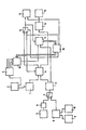
- the single figure shows a basic block diagram on which the various illustrated embodiment variants of the invention are to be described in more detail.
- the figure shows an assembly 1 for producing a model of the outer surface of the prosthesis blank, this assembly containing one or more prefabricated models of the prosthesis blank in spatial and physical implementation, which represents the outer contours of the initial shapes on a scale of 1: 1 or a corresponding reduction.
- these prosthesis models consist of a displaceable, i.e. plastically deformable, material.
- This blank can be changed via an input channel and can be adapted to the respective needs. Basically, however, essentially a single starting form is provided for all occurring applications.
- the input can, if appropriate, be read in by appropriate recording media, but also by inserting the respective blank into a scanning device which, in the manner of a so-called graphic tablet, provides a data representation of the prosthesis blank.
- the data of the prosthesis blank also arrive in an assembly 4 in which the strength data of the relevant prosthesis blank are stored.
- one or more three-dimensional models are stored, which can be called up individually and each represent a shape that guarantees the minimum strength requirements to be placed on a prosthesis.
- the data entering module 3 of the bone cavity model are alternatively obtained via various measures for digitizing x-ray images.
- Another option is to enter in the scanning of two-dimensional X-ray images by means of a graphic tablet, shown schematically as a block 5
- a graphic tablet shown schematically as a block 5
- the points of the contours of the inner cavity of the bone, into which the prosthesis is to be inserted are scanned point by point and stored in a subsequent assembly 6, which according to the method of the computer Aided designs from several X-ray images taken from different directions produce a three-dimensional representation of the interior of the bone.
- a corresponding procedure is used for two-dimensional images which are output by computer tomographs.
- This type of control is selected when a switch 7, which provides the necessary data link, is in its upper position.
- the data to be entered directly in three dimensions are either generated by a computer tomograph or via a spatial scanner 10, which functions in the same way as the graphics tablet 5, but offers the possibility of determining and outputting data of a third spatial coordinate.
- Both the computer tomograph 9 and the spatial scanner 10 can be used directly in the operation phase and serve to use the data on the nature of the bone cavity accommodating the prosthesis, which was determined during the operation phase either by X-ray analysis or by direct scanning, in order to generate a corresponding model .
- the model of the bone cavity 3, which is held in the assembly 3 or generated by it, and the model of the prosthesis blank, which is correspondingly available for the assembly 1, is - as explained - either only recorded in terms of data or as a spatial model from a plastic deformable material produced.
- plastically deformable materials are known with different plasticity properties.
- the "displaceability" here is assumed to be the resistance which opposes a certain volume of material, which is connected to another material in a preferably flat surface area, to a shear force acting on this volume parallel to this surface.
- the models according to assemblies 1 and 3 are produced from the deformable materials by numerically controlled machine tools, as are also used in other technical fields for the production of three-dimensional bodies.
- a first penetration takes place in an assembly 11, the model of the prosthesis blank of the assembly 1 being introduced into the model of the bone cavity of the assembly 3 by means of a suitable device.
- the model of the bone cavity is to be regarded as fixed in relation to the outer areas of the prosthesis model, while the prosthesis model is "displaceable".
- the material of the prosthesis blank is displaced in the manner described, since the material of the bone cavity can be relatively addressed as "solid".
- the path of minimal volume displacement for the prosthesis blank determined during insertion is recorded and passed on via a switching element 12 to an assembly 13 for controlling the later insertion of the prosthesis.
- the insertion process is ended when the position of a reference point connected to the prosthesis blank in the region of its shaft has reached a predetermined position relative to the bone.
- the remaining surface design of the prosthesis blank is, depending on the embodiment, transferred as a physical model in the data representation to a control module 14, where it serves as a pattern for controlling a milling machine 15 to generate the real prosthesis.
- this is a conventional copy milling machine into which the model of the prosthesis is input after it has previously been subjected to a curing process in the usual way.
- a comparison is carried out in order to determine the strength between the adapted model of the prosthesis blank and the strength models in assembly 4. At least one of the Existing strength models must be fully inscribed in the model obtained to ensure that the strength requirements are met. If the corresponding query is positive - and if there are several strength models, only one of them has to be inscribed in the manufacturing model - the manufacturing process can begin and no further measures are required. In the other case, the process proceeds as shown below if no intermediate control is carried out.
- an output signal is emitted to a control module 16, which causes an introduction of a strength model contained in the assembly 4 into the model of the bone cavity in a corresponding manner.
- the bone cavity is more displaceable than the strength model.
- the latter is firm with regard to the material of the bone.
- the control of the direction of insertion and the recording of the path covered during insertion takes place in an assembly 17, by means of which the corresponding insertion process is controlled.
- the path of the prosthesis (including rotations and changes in direction) is determined in such a way that the material of the model of the interior of the bone to be displaced when pushed forward is kept to a minimum.
- control assembly 14 automatically initiates the production of the real prosthesis by means of the milling machine 15 on the basis of the production model generated by the assembly 11.
- the assembly 17 outputs an output signal to the control part 16, which uses a selection unit 18 to select a differently designed strength model from the assembly 4, since different prosthesis models with minimal dimensions can be generated by changing curvatures and the like which meet the required strength requirements.
- the insertion process with minimal differential volume displacement of the model of the bone cavity and the distance covered are stored.
- the switch 12 is actuated by the output of the control module 16 and thus the determined path data is transferred to the assembly 13 for control when the prosthesis is inserted.
- this bone model must in turn be solid compared to the model of the prosthesis blank, so that after its introduction on the way as it was found for the strength model with minimal removal of bone substance, the model of the blank in turn becomes a production model for volume production by displacement a prosthesis is redesigned, which can be introduced into the cavity in the patient's bone, which has been changed by removing bone material, taking into account the changes in travel and rotational movements to be made.
- the location of the bone material to be removed is displayed to the treating surgeon via the control device for guiding when inserting the prosthesis 13 on a viewing device or the like, so that he can make the appropriate corrections to the interior of the bone.
- a check and a comparison can be carried out between the predetermined bone interior and the target data by means of the assembly 9 or 10.
- the path with minimal removal of bone substance and as little processing of the surface of the Prosthesis blanks can be combined with one another and can be carried out in one operation if the model of the interior of the bone has a medium displaceability.
- a high processing speed can be achieved in this way, since the number of extensive operations for moving data is spared if the local model data can be used several times in one operation.
- the spatial models will not displace, but will penetrate when the prosthesis model is advanced for insertion into the bone cavity.
- the volume which is described in the above as being "displaceable" in comparison to the other body is marked as eliminated, so that essentially the same considerations are relevant in this respect.
- the locations of mutual penetration by introducing the prosthesis model into the bone model are identified in suitable memory areas of the simulation computer by suitable binary signal states. Thus, those areas are preferably shown graphically to the surgeon by means of a display or plotter where bone removal is required. With minimal computational effort, you can move along the spatial areas of penetration accumulate. In the memory concerned, a memory location is simply assigned to each space point in question and the signal state of the memory location is changed in one bit if the respective space point was affected by a penetration of prostheses and the bone model. By comparing the graphic representations of the penetration areas found in this way when selecting different models with a given minimum strength, the surgeon can decide from the view which of the various prosthesis shapes he feels best - with bone removal that is necessary anyway - individually. Despite automated shape adaptation, the experience of the physician with different shapes and their properties - with mathematically almost identical properties of the determined prosthesis shapes - can thus be taken into account with different possible equivalent solutions.
- the digitized data determined by a computer tomograph are transmitted via the telephone network with corresponding circuit means and, after the model comparison according to the invention, are fed to an automatic milling machine.
- the transmission preferably takes place via a data network or a message channel prepared for the data transmission, as is given, for example, by the system screen text.
Landscapes
- Health & Medical Sciences (AREA)
- Engineering & Computer Science (AREA)
- Heart & Thoracic Surgery (AREA)
- Vascular Medicine (AREA)
- Geometry (AREA)
- Orthopedic Medicine & Surgery (AREA)
- Cardiology (AREA)
- Oral & Maxillofacial Surgery (AREA)
- Transplantation (AREA)
- Biomedical Technology (AREA)
- Physics & Mathematics (AREA)
- Manufacturing & Machinery (AREA)
- Life Sciences & Earth Sciences (AREA)
- Animal Behavior & Ethology (AREA)
- General Health & Medical Sciences (AREA)
- Public Health (AREA)
- Veterinary Medicine (AREA)
- Prostheses (AREA)
- Paper (AREA)
- Stringed Musical Instruments (AREA)
- Noodles (AREA)
Claims (10)
caractérisé par les étapes:
Priority Applications (1)
| Application Number | Priority Date | Filing Date | Title |
|---|---|---|---|
| AT84730118T ATE52686T1 (de) | 1983-11-03 | 1984-11-05 | Verfahren und vorrichtung zur herstellung einer endoprothese. |
Applications Claiming Priority (2)
| Application Number | Priority Date | Filing Date | Title |
|---|---|---|---|
| DE3340024 | 1983-11-03 | ||
| DE19833340024 DE3340024A1 (de) | 1983-11-03 | 1983-11-03 | Verfahren und vorrichtung zur herstellung eines prothesenschafts |
Publications (3)
| Publication Number | Publication Date |
|---|---|
| EP0146491A2 EP0146491A2 (fr) | 1985-06-26 |
| EP0146491A3 EP0146491A3 (en) | 1987-03-25 |
| EP0146491B1 true EP0146491B1 (fr) | 1990-05-16 |
Family
ID=6213530
Family Applications (1)
| Application Number | Title | Priority Date | Filing Date |
|---|---|---|---|
| EP84730118A Expired - Lifetime EP0146491B1 (fr) | 1983-11-03 | 1984-11-05 | Procédé et dispositif pour la production d'une endoprothèse |
Country Status (3)
| Country | Link |
|---|---|
| EP (1) | EP0146491B1 (fr) |
| AT (1) | ATE52686T1 (fr) |
| DE (2) | DE3340024A1 (fr) |
Families Citing this family (9)
| Publication number | Priority date | Publication date | Assignee | Title |
|---|---|---|---|---|
| DE3542016A1 (de) * | 1985-11-28 | 1987-06-04 | Orthoplant Endoprothetik | Individuell anpassbare hueftgelenk-endoprothese und verfahren zu ihrer herstellung |
| DE3626549A1 (de) * | 1986-08-06 | 1988-02-11 | Mecron Med Prod Gmbh | Verfahren zur herstellung einer endoprothese mit individueller anpassung |
| EP0256158A1 (fr) * | 1986-08-16 | 1988-02-24 | Ipos Gesellschaft für integrierte Prothesen-Entwicklung und orthopädietechnischen Service mbH & Co. KG | Prothèse, telle que prothèse de cuisse, ainsi que dispositif et procédé pour sa fabrication |
| DE3931143C2 (de) * | 1989-09-19 | 1998-05-20 | Rolf Prof Dr Ing Isermann | Verfahren zur Überwachung des Betriebs einer Werkzeugmaschine |
| US5360446A (en) * | 1992-12-18 | 1994-11-01 | Zimmer, Inc. | Interactive prosthesis design system for implantable prosthesis |
| FR2700000B1 (fr) * | 1992-12-29 | 1995-02-24 | Inst Francais Du Petrole | Procédé de reconstitution de volumes internes d'un solide en vue de calculs et application associée. |
| DE4341367C1 (de) * | 1993-12-04 | 1995-06-14 | Harald Dr Med Dr Med Eufinger | Verfahren zur Herstellung von Endoprothesen |
| GB2318058B (en) * | 1996-09-25 | 2001-03-21 | Ninian Spenceley Peckitt | Improvements relating to prosthetic implants |
| US10031989B2 (en) | 2014-11-18 | 2018-07-24 | Globalfoundries Inc. | Integrated circuit performance modeling using a connectivity-based condensed resistance model for a conductive structure in an integrated circuit |
Family Cites Families (3)
| Publication number | Priority date | Publication date | Assignee | Title |
|---|---|---|---|---|
| SE426437B (sv) * | 1981-05-14 | 1983-01-24 | Bock Otto Scandinavia Ab | Forfarande for tillverkning av en protes for en extremitet |
| DE3360592D1 (en) * | 1982-04-01 | 1985-09-26 | Ulmann Holding Ag | Lighting fitting centrally mounted in a support for receiving brightness-controlled lamps |
| DE3213434C1 (de) * | 1982-04-10 | 1983-10-27 | Günther Dr.med. 7400 Tübingen Aldinger | Verfahren zur Herstellung individuell gestalteter Endoprothesen oder Implantate |
-
1983
- 1983-11-03 DE DE19833340024 patent/DE3340024A1/de not_active Withdrawn
-
1984
- 1984-11-05 DE DE8484730118T patent/DE3482239D1/de not_active Expired - Fee Related
- 1984-11-05 AT AT84730118T patent/ATE52686T1/de not_active IP Right Cessation
- 1984-11-05 EP EP84730118A patent/EP0146491B1/fr not_active Expired - Lifetime
Also Published As
| Publication number | Publication date |
|---|---|
| DE3482239D1 (de) | 1990-06-21 |
| EP0146491A3 (en) | 1987-03-25 |
| ATE52686T1 (de) | 1990-06-15 |
| EP0146491A2 (fr) | 1985-06-26 |
| DE3340024A1 (de) | 1985-05-15 |
Similar Documents
| Publication | Publication Date | Title |
|---|---|---|
| EP2003616B1 (fr) | Analyse d'orientation pilotée par informatique dotée d'une projection de surfaces | |
| EP1208410B1 (fr) | Procede pour la generation d'implants specifiques aux patients | |
| EP0255797B1 (fr) | Méthode et appareil pour former une endoprothèse individuelle | |
| EP1399707B1 (fr) | Procede et dispositif de determination du contour d'une cavite pratiquee dans une piece | |
| DE60307194T2 (de) | Planung für die orthopädische Chirurgie | |
| EP2311009B1 (fr) | Procédé, système, dispositif et programme informatique pour créer une emboîture de prothèse | |
| EP1259185A2 (fr) | Procede pour naviguer a l'interieur du corps au moyen de structures visualisees en trois dimensions | |
| DE10357206B4 (de) | Verfahren und Bildbearbeitungssystem zur Segmentierung von Schnittbilddaten | |
| EP0731675A1 (fr) | Procede de fabrication d'endoprotheses | |
| DE102012217555A1 (de) | Verfahren und Computertomographie-System zur Ermittlung von Knochenmineraldichtewerten | |
| EP2002796A1 (fr) | Procédé de planification piloté par informatique pour la correction de modifications de formes d'articulations osseuses | |
| EP0146491B1 (fr) | Procédé et dispositif pour la production d'une endoprothèse | |
| WO2003063085A1 (fr) | Procede, dispositif et produit-programme logiciel permettant de creer un modele individuel d'une machoire | |
| DE102007034221A1 (de) | Verfahren zur virtuellen Anpassung eines Objekts an ein Körperteil eines Patienten | |
| EP1498851A1 (fr) | Détermination d'une forme tridimensionnelle d'un corps, en particulier d'une structure anatomique, à partir d'images de projection bidimensionnelles | |
| EP1843291A1 (fr) | Procédé et système d'élaboration d'une emboîture de prothèse | |
| DE102006044661A1 (de) | Ermittlungsverfahren für endgültige Porjektionsmatrizen | |
| EP2957251B1 (fr) | Dispositif d'utilisation dans un procédé de fabrication d'une structure d'implant dentaire | |
| DE102021201278A1 (de) | Verfahren zum Entwerfen einer Kiefergelenksprothese und entsprechendes Herstellungsverfahren | |
| DE10254943A1 (de) | Verfahren zum Herstellen eines Volumendatensatzes | |
| DE102016105208B3 (de) | Medizinisches Instrumentarium | |
| EP3030188B1 (fr) | Système pour la reconstruction de parties du corps symétriques | |
| EP4225224A1 (fr) | Procédé et programme informatique pour créer des données de fabrication, et procédé de fabrication d'un dispositif orthopédique | |
| DE102020127163B4 (de) | Verfahren zur Herstellung einer patientenindividuellen Endoprothese | |
| EP4374276A1 (fr) | Procédé et dispositif mis en oeuvre par ordinateur permettant la définition géométrique d'un composant adapté à une unité d'organisme |
Legal Events
| Date | Code | Title | Description |
|---|---|---|---|
| PUAI | Public reference made under article 153(3) epc to a published international application that has entered the european phase |
Free format text: ORIGINAL CODE: 0009012 |
|
| AK | Designated contracting states |
Designated state(s): AT BE CH DE FR GB IT LI |
|
| PUAL | Search report despatched |
Free format text: ORIGINAL CODE: 0009013 |
|
| AK | Designated contracting states |
Kind code of ref document: A3 Designated state(s): AT BE CH DE FR GB IT LI |
|
| 17P | Request for examination filed |
Effective date: 19870702 |
|
| 17Q | First examination report despatched |
Effective date: 19881102 |
|
| GRAA | (expected) grant |
Free format text: ORIGINAL CODE: 0009210 |
|
| AK | Designated contracting states |
Kind code of ref document: B1 Designated state(s): AT BE CH DE FR GB IT LI |
|
| PG25 | Lapsed in a contracting state [announced via postgrant information from national office to epo] |
Ref country code: IT Free format text: LAPSE BECAUSE OF FAILURE TO SUBMIT A TRANSLATION OF THE DESCRIPTION OR TO PAY THE FEE WITHIN THE PRESCRIBED TIME-LIMIT;WARNING: LAPSES OF ITALIAN PATENTS WITH EFFECTIVE DATE BEFORE 2007 MAY HAVE OCCURRED AT ANY TIME BEFORE 2007. THE CORRECT EFFECTIVE DATE MAY BE DIFFERENT FROM THE ONE RECORDED. Effective date: 19900516 Ref country code: BE Effective date: 19900516 |
|
| REF | Corresponds to: |
Ref document number: 52686 Country of ref document: AT Date of ref document: 19900615 Kind code of ref document: T |
|
| REF | Corresponds to: |
Ref document number: 3482239 Country of ref document: DE Date of ref document: 19900621 |
|
| ET | Fr: translation filed | ||
| GBT | Gb: translation of ep patent filed (gb section 77(6)(a)/1977) | ||
| PG25 | Lapsed in a contracting state [announced via postgrant information from national office to epo] |
Ref country code: AT Effective date: 19901105 |
|
| PLBE | No opposition filed within time limit |
Free format text: ORIGINAL CODE: 0009261 |
|
| STAA | Information on the status of an ep patent application or granted ep patent |
Free format text: STATUS: NO OPPOSITION FILED WITHIN TIME LIMIT |
|
| 26N | No opposition filed | ||
| PGFP | Annual fee paid to national office [announced via postgrant information from national office to epo] |
Ref country code: GB Payment date: 19911024 Year of fee payment: 8 |
|
| PGFP | Annual fee paid to national office [announced via postgrant information from national office to epo] |
Ref country code: FR Payment date: 19911114 Year of fee payment: 8 |
|
| PGFP | Annual fee paid to national office [announced via postgrant information from national office to epo] |
Ref country code: CH Payment date: 19911218 Year of fee payment: 8 |
|
| PG25 | Lapsed in a contracting state [announced via postgrant information from national office to epo] |
Ref country code: GB Effective date: 19921105 |
|
| PG25 | Lapsed in a contracting state [announced via postgrant information from national office to epo] |
Ref country code: LI Effective date: 19921130 Ref country code: CH Effective date: 19921130 |
|
| PGFP | Annual fee paid to national office [announced via postgrant information from national office to epo] |
Ref country code: DE Payment date: 19930121 Year of fee payment: 9 |
|
| GBPC | Gb: european patent ceased through non-payment of renewal fee |
Effective date: 19921105 |
|
| PG25 | Lapsed in a contracting state [announced via postgrant information from national office to epo] |
Ref country code: FR Effective date: 19930730 |
|
| REG | Reference to a national code |
Ref country code: CH Ref legal event code: AUV Free format text: DIE OBENGENANNTEN PATENTE SIND, MANGELS BEZAHLUNG DER 9. JAHRESGEBUEHR GELOESCHT WORDEN. Ref country code: CH Ref legal event code: PL |
|
| REG | Reference to a national code |
Ref country code: FR Ref legal event code: ST |
|
| PG25 | Lapsed in a contracting state [announced via postgrant information from national office to epo] |
Ref country code: DE Effective date: 19940802 |