EP0146491B1 - Method and device for the production of an endoprosthesis - Google Patents
Method and device for the production of an endoprosthesis Download PDFInfo
- Publication number
- EP0146491B1 EP0146491B1 EP84730118A EP84730118A EP0146491B1 EP 0146491 B1 EP0146491 B1 EP 0146491B1 EP 84730118 A EP84730118 A EP 84730118A EP 84730118 A EP84730118 A EP 84730118A EP 0146491 B1 EP0146491 B1 EP 0146491B1
- Authority
- EP
- European Patent Office
- Prior art keywords
- prosthesis
- model
- path
- bone cavity
- bone
- Prior art date
- Legal status (The legal status is an assumption and is not a legal conclusion. Google has not performed a legal analysis and makes no representation as to the accuracy of the status listed.)
- Expired - Lifetime
Links
Images
Classifications
-
- A—HUMAN NECESSITIES
- A61—MEDICAL OR VETERINARY SCIENCE; HYGIENE
- A61F—FILTERS IMPLANTABLE INTO BLOOD VESSELS; PROSTHESES; DEVICES PROVIDING PATENCY TO, OR PREVENTING COLLAPSING OF, TUBULAR STRUCTURES OF THE BODY, e.g. STENTS; ORTHOPAEDIC, NURSING OR CONTRACEPTIVE DEVICES; FOMENTATION; TREATMENT OR PROTECTION OF EYES OR EARS; BANDAGES, DRESSINGS OR ABSORBENT PADS; FIRST-AID KITS
- A61F2/00—Filters implantable into blood vessels; Prostheses, i.e. artificial substitutes or replacements for parts of the body; Appliances for connecting them with the body; Devices providing patency to, or preventing collapsing of, tubular structures of the body, e.g. stents
- A61F2/02—Prostheses implantable into the body
- A61F2/30—Joints
- A61F2/3094—Designing or manufacturing processes
- A61F2/30942—Designing or manufacturing processes for designing or making customized prostheses, e.g. using templates, CT or NMR scans, finite-element analysis or CAD-CAM techniques
- A61F2002/30952—Designing or manufacturing processes for designing or making customized prostheses, e.g. using templates, CT or NMR scans, finite-element analysis or CAD-CAM techniques using CAD-CAM techniques or NC-techniques
-
- A—HUMAN NECESSITIES
- A61—MEDICAL OR VETERINARY SCIENCE; HYGIENE
- A61F—FILTERS IMPLANTABLE INTO BLOOD VESSELS; PROSTHESES; DEVICES PROVIDING PATENCY TO, OR PREVENTING COLLAPSING OF, TUBULAR STRUCTURES OF THE BODY, e.g. STENTS; ORTHOPAEDIC, NURSING OR CONTRACEPTIVE DEVICES; FOMENTATION; TREATMENT OR PROTECTION OF EYES OR EARS; BANDAGES, DRESSINGS OR ABSORBENT PADS; FIRST-AID KITS
- A61F2/00—Filters implantable into blood vessels; Prostheses, i.e. artificial substitutes or replacements for parts of the body; Appliances for connecting them with the body; Devices providing patency to, or preventing collapsing of, tubular structures of the body, e.g. stents
- A61F2/02—Prostheses implantable into the body
- A61F2/30—Joints
- A61F2/3094—Designing or manufacturing processes
- A61F2/30942—Designing or manufacturing processes for designing or making customized prostheses, e.g. using templates, CT or NMR scans, finite-element analysis or CAD-CAM techniques
- A61F2002/30957—Designing or manufacturing processes for designing or making customized prostheses, e.g. using templates, CT or NMR scans, finite-element analysis or CAD-CAM techniques using a positive or a negative model, e.g. moulds
Abstract
Description
Die Erfindung betrifft verschiedene Verfahren zur Herstellung einer Prothese, wie sie in den Oberbegriffen der Ansprüche 1 bis 4 angegeben sind sowie Vorrichtungen zur Durchführung dieser Verfahren.The invention relates to various methods for producing a prosthesis, as specified in the preambles of claims 1 to 4, and to devices for carrying out these methods.
Bei der Herstellung von Prothesen und insbesondere von gekrümmenten Prothesenschäften stellt deren Anpassung an die individuellen Abmessungen der Hohlräume in den den jeweiligen schaft aufnehmenden Knochen ein Problem dar, das derzeit durch das Vorrätighalten von Schäften in den verschiedensten Abmessungen gelöst wird.In the manufacture of prostheses and, in particular, curved prosthesis sockets, their adaptation to the individual dimensions of the cavities in the bones receiving the respective shaft presents a problem which is currently being solved by stocking sockets in a wide variety of dimensions.
Nachteilig war dabei, daß selbst bei umfangreicher Lagerhaltung nicht allen sich bei der Operation stellenden Anforderungen entsprochen werden konnte und zur individuellen Anpassung vielfach Knochensubstanz zusätzlich beseitigt werden mußte, welche bei exakter Anpassung hätte erhalten bleiben können. Berücksichtigt werden muß dabei auch die Einsetzbarkeit von gekrümmten Prothesenschäften, wobei die zusätzliche Problematik besteht, daß einerseits genügend Raum vorhanden sein muß, um den gekrümmten Prothesenschaft trotz der in der Einführungsöffnung des Knochens ebenfalls vorhandenen Krümmung korrekt einzuführen und andererseits im eingesetzten Zustand einen festen Sitz der Prothese, insbesondere bei zementfreier Implantation sicherzustellen.The disadvantage here was that even with extensive warehousing, not all of the requirements arising from the operation could be met and, for individual adaptation, bone substance had to be removed in many cases, which could have been retained with exact adaptation. The usability of curved prosthesis sockets must also be taken into account, with the additional problem that there must be enough space on the one hand to correctly insert the curved prosthesis socket despite the curvature also present in the insertion opening of the bone and, on the other hand, a firm fit in the inserted state Ensure prosthesis, especially with cementless implantation.
Aus der DE 32 13 434 CI ist auch ein Verfahren bekannt geworden, welches die Herstellung individuell gestalteter Prothesen oder Implantate mittels Computer-Tomographie und Computereinsatz bei der nachfolgenden Berechnung beschreibt. Dabei besteht jedoch ein Problem darin, daß bei gekrümmten Prothesenteilen zwar eine optimal passende Prothese hergestellt, diese aber durch eine vorhandene Knochenöffnung oder einen bestehenden Zugangsweg nicht eingeführt werden kann.From DE 32 13 434 CI a method has also become known which describes the manufacture of individually designed prostheses or implants by means of computer tomography and computer use in the subsequent calculation. However, there is a problem in that, in the case of curved prosthesis parts, an optimally fitting prosthesis is produced, but it cannot be inserted through an existing bone opening or an existing access path.
Bei gekrümmten Prothesenschäften besteht die Problematik vor allem darin, daß einerseits genügend Raum vorhanden sein muß, um den gekrümmten Prothesenschaft trotz der im inneren Knochenraum entsprechend vorhandenen Krümmung oder Verwindung korrekt einführen zu können und andererseits im eingesetzten Zustand ein fester Sitz der Prothese - insbesondere bei zementfreier Implantation-sicherzustellen ist.The problem with curved prosthesis stems is primarily that there must be enough space on the one hand to be able to correctly insert the curved prosthesis socket despite the corresponding curvature or twist in the inner bone space, and on the other hand that the prosthesis is firmly seated when inserted - especially with cementless ones Implantation is to be ensured.
Den in den Ansprüchen 1 bis 4 angegebenen Verfahren liegt die Aufgabe zugrunde, individuelle, an die vorgefundenen oder erzeugten Knochenhohlräume optimal angepaßte Prothesen unter berücksichtigung von deren Einsetzbarkeit bei Krümmungen der betreffenden Hohlräume zu ermöglichen.The object of the methods specified in claims 1 to 4 is to enable individual prostheses that are optimally adapted to the bone cavities found or produced, taking into account their usability in the case of curvatures of the cavities in question.
Diese Problematik stellt sich immer dann, wenn die zur Verfügung stehende Knochenöffnung kleiner ist als der durch Projektion zu erzeugende Schattenriß der notwendigen Endoprothese - die in diesem Fall nicht mittels einer linearen rotationsfreien Bewegung einführbar ist.This problem always arises when the available bone opening is smaller than the silhouette of the necessary endoprosthesis to be generated by projection - which in this case cannot be introduced by means of a linear, rotation-free movement.
Die Erfindung beruht auf der Erkenntnis, daß bei der Verwendung von Prothesen eine Mindesttragfähigkeit berücksichtigt werden muß, welche entsprechend eine Mindestbaugröße der Prothese erfordert, wobei diese geforderte Mindesttragfähigkeit eine unterschiedliche Formgestaltung annehmen kann und besonderen Anforderungen noch durch die Auswahl des Werkstoffes innerhalb der für Implantationszwecke zur Verfügung stehenden körperverträglichen Werkstoffe Rechnung getragen werden kann.The invention is based on the knowledge that when using prostheses, a minimum load-bearing capacity must be taken into account, which accordingly requires a minimum size of the prosthesis, whereby this required minimum load-bearing capacity can take on a different shape and special requirements due to the selection of the material within that for implantation purposes Available physically compatible materials can be taken into account.
Durch die Erzeugung des Modells der Knochenhöhlung besteht die Möglichkeit - vorzugsweise mittels Simulation durch einen Computer - den Weg des optimalen Einführens und die beste Form des Schaftes zu bestimmen. Dabei wird durch die verdrängbare Konsistenz der Prothesenaußenkontur, welche außerhalb der für die Tragfähigkeit erforderlichen minimalen Festigkeitszone gelegen ist, am Modell ermittelt, welche Bereiche des Prothesenrohlings abzutragen sind.By generating the model of the bone cavity, it is possible - preferably by means of a computer simulation - to determine the path of optimal insertion and the best shape of the shaft. The displaceable consistency of the outer contour of the prosthesis, which lies outside the minimum strength zone required for the load-bearing capacity, is used to determine which areas of the prosthesis blank are to be removed.
Der Prothesenrohling braucht damit für alle vorkommenden Fälle nur jeweils in einer Ausführung vorhanden zu sein - es sei denn es sollen auch unterschiedliche Werkstoffe zur Ver wendung kommen. Die Mindeststruktur zur Aufrechterhaltung der Tragfähigkeit der Prothese ist in den zur Verwendung kommenden Modellen ebenfalls herausmodelliert. Diese Mindeststruktur muß erhalten bleiben, so daß eine Verklemmung, die ein Einführen der Prothese innerhalb dieser Mindeststruktur verhindert, durch Abtragung von Knochenmaterial ermöglicht werden muß. Insbesondere durch Vorsehen unterschiedlicher Formen dieser Mindeststruktur kann die somit noch notwendige Abtragung von Knochenmaterial auf ein Minimum reduziert werden.The prosthesis blank therefore only needs to be available in one version for all occasions - unless different materials are to be used. The minimum structure for maintaining the load-bearing capacity of the prosthesis is also modeled out in the models to be used. This minimum structure must be maintained so that jamming, which prevents insertion of the prosthesis within this minimum structure, must be made possible by the removal of bone material. In particular, by providing different forms of this minimum structure, the removal of bone material that is still necessary can be reduced to a minimum.
Unter "Prothesenrohling" ist hier zweckmäßigerweise eine Ausgangsform zu verstehen, welche die maximale Größe eines für den betreffenden Anwendungsfall in Betracht kommenden Typs bildet. Letztendlich könnte aber auch von einem beliebigen Rohling ausgegangen werden, wenn der notwendige Materialabtrag in Kauf genommen wird."Prosthesis blank" here is expediently to be understood as an initial shape which forms the maximum size of a type that is suitable for the application in question. Ultimately, however, any blank could be assumed if the necessary material removal is accepted.
Die Ausführung der erfindungsgemäßen Verfahren läßt damit unterschiedliche Varianten zu:
- bei einer ersten Variante ist das einzuführende Modell der Prothese zweischichtig ausgebildet, in seinen inneren und äußeren Teilen eine unterschiedliche Konsistenz. Die äußeren Bereiche sind leichter verdrängbar, so daß sie beim Einführen in das Modell der Knochenhöhlung beseitigt werden. Die Konsistenz des inneren Kernes mit der Mindeststruktur hat eine höhere Festeigkeit (kleinere Verdrängbarkeit) als das Innere des Modells der Knochenhöhlung. Bei diesem ersten Modell würde also das Volumen der äußeren bereiche der Prothese durch das Modell der Knochensubstanz und das Volumen des Modells der Knochenhöhlung durch den Kernbereich der Prothese verdrängt werden. Das Einführen der Prothese erfolgt dabei auf einem Weg der geringsten Verdrängung vom Volumen der Knochenhöhlung jeweils bezogen auf kleine (differentielle) Vorschübe der Prothese innerhalb der Höhlung.
- In a first variant, the model of the prosthesis to be introduced is formed in two layers, with a different consistency in its inner and outer parts. The outer areas are easier to displace so that they are removed when inserted into the bone cavity model. The consistency of the inner core with the minimum structure has a higher strength (less displaceability) than the inside of the model of the bone cavity. In this first model, the volume of the outer regions of the prosthesis would be displaced by the model of the bone substance and the volume of the model of the bone cavity by the core region of the prosthesis. The prosthesis is inserted in a way of minimal displacement from the volume of the bone cavity in relation to small (differential) fores push the prosthesis inside the cavity.
Auf diese Weise entsteht nach Beseitigung des verdrängbaren Materials im äußeren Bereich des Modells des Prothesenschaftes eine Vorlage zum Erzeugen der realen Prothese mittels eines numerisch gesteuerten Fräsautomaten aus einem vorgegebenen Rohling.In this way, after removal of the displaceable material in the outer area of the model of the prosthesis socket, a template is created for producing the real prosthesis by means of a numerically controlled automatic milling machine from a predetermined blank.
Der beim Einführen der fertigen prothese einzuschlagende Weg und die dabei notwendige räumliche Orientierung sowie Ort und Menge des möglicherweise noch zu entfernenden Knochenmaterial werden dokumentiert und dem behandelnden Chirugen für die Operation zur Verfügung gestellt. Auf diese Weise ist ein optimaler Sitz des so gefertigten Prothesenschaftes sichergestellt. Berücksichtigt ist dabei auch, daß die günstigste Form des Prothesenschaftes - ins besondere bei Hüftgelenkprothesen - unter Ausnutzung der gegebenen anatomischen Verhältnisse bevorzugt eine Rotation beim Einführen verlangt, der mittels der erfindungsgemäßen Verfahren in besonders vorteilhafter Weise Rechnung getragen werden kann.The path to be taken when inserting the finished prosthesis and the necessary spatial orientation as well as the location and amount of any bone material that may still need to be removed are documented and made available to the surgeon treating them for the operation. In this way, an optimal fit of the prosthesis socket manufactured in this way is ensured. It is also taken into account that the cheapest form of the prosthesis socket - especially in the case of hip joint prostheses - using the given anatomical conditions preferably requires a rotation during insertion, which can be taken into account in a particularly advantageous manner by means of the method according to the invention.
Wenn davon ausgegangen werden kann, daß Substanz des Knochens nicht entfernt zu werden braucht, ist lediglich ein homogenes Prothesenmodell erforderlich, (Anspruch 1) wobei ausschließlich Material dieses Schaftmodells verdrängt wird. Nach erfolgtem Einführen des Modells kann gegebenenfalls überprüft werden, ob der verbleibende "Restschaft" noch die notwendige Festigkeit aufweist.If it can be assumed that the substance of the bone does not need to be removed, all that is required is a homogeneous prosthetic model (claim 1), only material of this shaft model being displaced. After the model has been introduced, it can be checked, if necessary, whether the remaining "remainder" still has the necessary strength.
Bei einer dritten Ausführungsvariante wird diese Überprüfung durch ein zweites Schaftmodell vorgenommen, welches in ein Modell der Knochenbildung mit einer Konsistenz mittlerer Verdrängbarkeit eingeführt wird, so daß bei dieser Ausführung des Verfahrens die beiden Schichten des Schaftmodells gemäß dem ersten Verfahren praktisch nacheinander ausgeführt werden.In a third embodiment variant, this check is carried out by a second shaft model, which is introduced into a model of bone formation with a consistency of medium displacement, so that in this embodiment of the method the two layers of the shaft model are practically carried out in succession according to the first method.
Steht hierbei neben einem festen Werkstoff lediglich ein solcher einer einzigen Verdrängbarkeitsklasse zur Verfügung, so werden die beiden Einführungen nacheinander mit zwei bezüglich ihrer Form übereinstimmenden Knochenmodellen ausgeführt, von denen eines fest und das andere verdrängbar ist. Der Begriff "verdrängbar" soll im Zusammenhang mit der Erfindung stets synomym mit "beseitigbar" verstanden werden, da es für das erfindungsgemäße Verfahren nicht von Bedeutung ist, wo der abgetragene Werkstoff verbleibt. Insbesondere für die Computersimulation wird er als beseitigt angesehen. Bei Realisierungen einer Vorrichtung zur Durchführung des Verfahrens kann das "Abtragen" bevorzugt auch in der Weise erfolgen, daß das jeweils widerstandsfähigere oder härtere Modell durch eine Abtragungsvorrichtung gebildet wird, welche von dem "weicheren" Modell den "verdrängten" Teil entfernt, was bevorzugt durch einen numerisch gesteuerten Fräsautomaten oder ein ensprechendes Laser-Schneidgerät erfolgen kann, wenn der jeweilige Modell - Werkstoff entsprechend ausgewählt ist.If, in addition to a solid material, only one of a single displaceability class is available, the two introductions are carried out in succession with two bone models which have the same shape, one of which is fixed and the other of which is displaceable. The term "displaceable" should always be understood synonymously with "eliminable" in connection with the invention, since it is not important for the method according to the invention where the removed material remains. For computer simulation in particular, it is considered to be eliminated. When realizing a device for carrying out the method, the "removal" can preferably also take place in such a way that the respectively more resistant or harder model is formed by a removal device which removes the "displaced" part of the "softer" model, which is preferably by a numerically controlled automatic milling machine or a corresponding laser cutting device can take place if the respective model - material is selected accordingly.
Bei der Ermittlung der Form einer Prothese mit ausreichender Mindestfestigkeit ist auch noch die Festigkeit des verbleibenden Knochenmaterials in betracht zu ziehen. Weiterhin muß bei der Wahl eines Prothesenmodells, welches eine notwendige Mindestfestigkeit aufweist, das jeweilige Körpergewicht des Patienten berücksichtigt werden. Diese zusätzlichen Bedingungen beeinflussen aber nicht den grundsätzlichen Weg der Anpassung eines Prothesenschafts nach dem erfindungsgemäßen Verfahren.When determining the shape of a prosthesis with sufficient minimum strength, the strength of the remaining bone material must also be taken into account. Furthermore, when choosing a prosthesis model that has a necessary minimum strength, the respective body weight of the patient must be taken into account. However, these additional conditions do not influence the basic way of adapting a prosthesis socket using the method according to the invention.
Die Erfindung kann in beliebiger weise ausgeführt werden, wobei die Modellerzeugung entweder konkret räumlichkörperlich mittels werkstoffverdrängender oder abtragender Werkzeuge oder aber durch Computersimulation vorgenommen werden kann. Die differentielle räumliche Verdrängung des Werkstoffes der Prothese oder Oberfläche des Knocheninnenraumes wird dabei durch eine Ermittlung der für den Vorschub erforderlichen Kraft vorgenommen, wobei durch geringfügige Veränderung der Vorschubrichtung (Rotation) der Prothese beim Einführen oder deren Richtungsänderung die Orientierung und Richtung des Vorschubs mit geringstem Kraftaufwand festgestellt wird, so daß ein Einschieben mit minimalem Werkstoffabtrag erfolgt.The invention can be carried out in any manner, and the model can be generated either spatially by means of material-displacing or ablating tools or by computer simulation. The differential spatial displacement of the material of the prosthesis or surface of the interior of the bone is carried out by determining the force required for the advancement, whereby by slightly changing the direction of advance (rotation) of the prosthesis during insertion or changing its direction, the orientation and direction of the advancement with minimal effort is determined so that insertion takes place with minimal material removal.
Bei der Durchführung des modellmäßige Anpassens mittels elektronischer Datenverarbeitung wird von einem System mit "Computer - Aided - Design (CAD) Gebrauch gemacht, wobei eine räumliche Durchdringung der beiden Modelle erfolgt. Dabei wird der dem Restkörper zugewandte Teil des Körpers mit der höheren Verdrängbarkeit als beseitigt angenommen und eliminiert. Die Steuerung der Vorschubrichtung und die dabei einzuhaltende räumliche Orientierung des Prothesenmodells wird durch Ermittlung des jeweils beim Vorschub verdrängten Prothesenmaterials über differentielle Weglängen festgestellt. Der zurückgelegte Weg beim Einführen wird in einem entsprechenden Speicher festgehalten, wobei ein räumliches Koordinatensystem zur Orientierung dient.When performing the model-based adaptation by means of electronic data processing, a system with "computer-aided design (CAD)" is used, in which the two models are penetrated spatially. The part of the body that faces the residual body and is more displaceable than is eliminated The control of the feed direction and the spatial orientation of the prosthesis model to be observed is determined by determining the prosthesis material that is displaced during the feed via differential path lengths. The path covered during insertion is recorded in a corresponding memory, a spatial coordinate system being used for orientation.
Die erfindungsgemäßen Verfahren bzw. die entsprechenden Vorrichtungen zu deren Durchführung ermöglichen auf mannigfaltige Weise eine Optimierung des Prothesensitzes durch genaue Anpassung von Prothesenform und Knochenabtrag.The methods according to the invention and the corresponding devices for their implementation enable the prosthesis seat to be optimized in a variety of ways by precisely adapting the shape of the prosthesis and the removal of bone.
Das gemeinsame Grundprinzip bei den zweistufigen Verfahren besteht darin, daß zum einen der notwendige Materialabtrag der Prothese ermittelt wird, zum anderen aber die Einführbarkeit einer Prothesenform minimaler Mindestfestigkeit durch zusätzliche Knochenabtragung gewährleistet wird. Der bei der Einführung der Prothese einzuschlagende Weg - ein - schließlich Richtungsänderungen und Drehbewegungen -.wird bei einer Form der erfindungsgemäßen Verfahren bei der Ermittlung des wegs mit minimalem Materialabtrag bei der Prothese ermittelt. Ausgegangen wird dabei von einem Prothesenrohling, dessen Form allgemeinsten Anwendungen angepasst ist.The common basic principle in the two-stage method is that the necessary material removal of the prosthesis is determined on the one hand, and on the other hand the insertability of a prosthesis shape of minimum minimum strength is ensured by additional bone removal. The path to be taken when introducing the prosthesis - including changes in direction and rotational movements - is determined in one form of the method according to the invention when determining the path with minimal material removal in the prosthesis. The starting point is a prosthetic blank, the shape of which is adapted to the most general applications.
Sollte sich jedoch herausstellen, daß das Prothesenmodell mit minimaler Mindestfestigkeit beim Einführen die Abtragung von Knochenmaterial erforderlich macht, so wird bei einer anderen bevorzugten Ausführung des erfindungsgemäßen Verfahrens der Einführungsweg der Prothese derart festgelegt, daß ein minimaler Abtrag von Knochenmaterial erforderlich ist, sobald festgestellt ist, daß eine derartige Knochenmaterialabtragung erforderlich ist. Die Festlegung des erforderlichen Materialabtrags wird dann auf dem letztgenannten Weg wiederholt.However, if it turns out that the prosthesis model with a minimum minimum strength during insertion requires the removal of bone material, in another preferred embodiment of the method according to the invention the insertion path of the prosthesis is determined such that a minimal removal of bone material is required as soon as it is established, that such bone removal is required. The determination of the required material removal is then repeated in the latter way.
Bei einer anderen Ausführungsvariante der Erfindung wird die Menge des abzutragenden Knochenmaterials noch dadurch verringert, daß mit verschiedenen Prothesenmodellen minimaler Mindestfestigkeit, welche eine unterschiedliche Formgebung aufweisen oder aber denen werkstoffe unterschiedlicher Festigkeit zugrunde liegen, nacheinander auf dem Weg minimalen Knochenabtrags eingeführt werden, wobei abschließend diejenige Form minimaler Mindestfestigkeit gewählt wird, auf dem insgesamt der Abtrag geringsten Knochenvolumens festgestellt wurde.In another embodiment variant of the invention, the amount of bone material to be removed is further reduced by successively introducing minimal bone abrasion with different prosthesis models of minimal minimum strength, which have a different shape or which are based on materials of different strength, on the way, finally that shape minimum minimum strength is selected, on which the removal of the smallest bone volume was determined.
Die vorstehend dargestellte Wegermittlung kann nacheinander oder - bei Verwendung von Mehrschichtmodellen - gleichzeitig erfolgen. Lediglich bei den Verfahrensstufen zur Festlegung eines Weges oder einer Prothesenform mit minimaler Mindestfestigkeit unter Berücksichtung des minimalen Knochenabtrags ist ein rekursives Verfahren insoweit erforderlich, als nacheinander verschiedene Formen minimaler Mindestfestigkeit erprobt werden sollen oder aber der Materialabtrag beim Prothesenrohling durch den Weg minimaler Materialabtragung von Knochenmaterial beeinflußt wird.The route determination described above can be carried out in succession or - when using multilayer models - simultaneously. A recursive procedure is only necessary for the process stages for determining a path or a prosthesis shape with minimum minimum strength, taking into account the minimum bone removal, insofar as different forms of minimum minimum strength are to be tested in succession or the material removal in the prosthesis blank is influenced by the path of minimal material removal of bone material .
Einen anderen Aspekt der Erfindung bildet die Umwandlung der die Knochenöffnung betreffenden Daten von der Erfassung am Patienten in solche Größen, welche die Erzeugung eines Modells ermöglichen. Grundsätzlich erfolgt die Ermittlung dieser Daten aufgrund von Röntgenbildern, welche jedoch jeweils nur eine zweidimensionale Darstellung erlauben. Mittels eines Rechners, der nach dem Prinzip des "Computer-Aided-Design" (CAD) arbeitet, ist es jedoch möglich, aus mehreren zweidimensionalen Darstellungen das zugehörige dreidimensionale Modell festzulegen. Entsprechend wird auch bei zweidimensionalen Darstellungen verfahren, welche mittels eines Computertomografen erzeugt werden. Insoweit wird hinsichtlich der Ausführung auf die DE-32 13 434-CI verwiesen.Another aspect of the invention is the conversion of the data relating to the opening of the bone from the acquisition on the patient into those sizes which enable the generation of a model. Basically, this data is determined on the basis of X-ray images, which, however, only allow a two-dimensional representation. However, by means of a computer that works on the principle of "computer-aided design" (CAD), it is possible to determine the associated three-dimensional model from several two-dimensional representations. The same procedure is used for two-dimensional representations that are generated by means of a computer tomograph. In this regard, reference is made to DE-32 13 434-CI with regard to the design.
Besonders vorteilhaft ist jedoch die direkte Umwandlung von dreidimensionalen - Abbildungen in das Modell des Knochenhohlraumes. Dabei sind bevorzugt zwei Wege gangbar: Der eine besteht darin, daß eine direkte Digitalisierung einer mittels Computertomogramm erzeugten dreidimensionalen Abbildung erzeugt wird. Eine andere besteht darin, daß während der Operation der Knocheninnenraum, der für die, Einführung der Prothese vorgesehen ist, abgetastet wird und durch "On - line" - Verknüpfung mit dem zugehörigen Rechner und der nachgeschalteten Werkzeugmaschine sofort eine passende Prothese erzeugt wird, welche aus der sterilen Herstellung direkt in den Operationssaal gelangt.However, the direct conversion of three-dimensional images into the model of the bone cavity is particularly advantageous. Two ways are preferred: One is that a direct digitization of a three-dimensional image generated by means of a computer tomogram is generated. Another is that during the operation the bone interior, which is intended for the introduction of the prosthesis, is scanned and an "on-line" link with the associated computer and the downstream machine tool immediately produces a suitable prosthesis, which is made up of of sterile production goes directly into the operating room.
Vorteilhafte Weiterbildungen der Erfindung sind in den Unteransprüchen gekennzeichnet bzw. werden bei der nachstehenden Darstellung zusammen mit einer bevorzugten Ausführung der Erfindung näher beschrieben.Advantageous developments of the invention are characterized in the subclaims or are described in more detail in the following illustration together with a preferred embodiment of the invention.
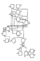
Die einzige Figur zeigt ein grundsätzliches blockschaltbild an dem die verschiedenen dargestellten Ausführungsvarianten der Erfindung näher beschrieben werden sollen.The single figure shows a basic block diagram on which the various illustrated embodiment variants of the invention are to be described in more detail.
In der Figur ist eine Baugruppe 1 zur Erzeugung eines Modells der Außenoberfläche des Prothesenrohlings wiedergegeben, wobei diese baugruppe bei räumlich - körperlicher Realisierung ein oder mehrere vorgefertigte Modelle des Prothesenrohlings enthält, der im Maßstab 1:1 oder einer entsprechenden Verkleinerung die Außenkonturen der Ausgangsformen repräsentiert. Bei räumlich - körperlicher Realisierung bestehen diese Prothesenmodelle aus einem verdrängbaren, d.h. plastisch verformbaren, Werkstoff. Bei der Ausführung mittels Simulation durch eine Datenverarbeitungsanlage sind Speicher vorgesehen, welche die Daten der Oberflächenkontur enthalten oder aber bestimmten räumlichen Punkten zugeordnet sind und wenn sie eine Information enthalten, auf die Tatsache hinweisen, daß der zugeordnete Raumpunkt von dem Prothesenrohling ausgefüllt ist.The figure shows an assembly 1 for producing a model of the outer surface of the prosthesis blank, this assembly containing one or more prefabricated models of the prosthesis blank in spatial and physical implementation, which represents the outer contours of the initial shapes on a scale of 1: 1 or a corresponding reduction. In the case of spatial and physical implementation, these prosthesis models consist of a displaceable, i.e. plastically deformable, material. When executed by means of simulation by a data processing system, memories are provided which contain the data of the surface contour or are assigned to certain spatial points and, if they contain information, indicate the fact that the assigned space point is filled by the prosthesis blank.
Über einen Eingabekanal ist die Form dieses Rohlings veränderbar und kann den jeweiligen Bedürfnissen angepaßt werden. Grundsätzlich ist jedoch im wesentlichen eine einzige Ausgangsform für alle vorkommenden Anwendungsfälle vorgesehen.The shape of this blank can be changed via an input channel and can be adapted to the respective needs. Basically, however, essentially a single starting form is provided for all occurring applications.
Die Eingabe kann bei simulierter Verarbeitung durch Einlesen von entsprechenden Aufzeichnungsträgern gegebenenfalls aber auch durch Einlegen des jeweiligen Rohlings in eine Abtastvorrichtung, welche nach Art eines sogenannten Grafik - Tabletts eine Datenrepräsentation des Prothesenrohlings liefert.In the case of simulated processing, the input can, if appropriate, be read in by appropriate recording media, but also by inserting the respective blank into a scanning device which, in the manner of a so-called graphic tablet, provides a data representation of the prosthesis blank.
Von der Eingabe Baugruppe 2 gelangen die Daten des Prothesenrohlings auch in eine Baugruppe 4, in der die Festigkeitsdaten des betreffenden Prothesenrohlings gespeichert werden. Insbesondere werden ein oder mehrere dreidimensionale Modelle gespeichert, die einzeln abrufbar sind und jeweils eine Formgebung repräsentieren, die die an eine Prothese zu stellenden Mindestfestigkeitsanforderungen garantieren. Dabei überlagern sich die Modelle, welche in den Baugruppen 1 und 4 festgehalten werden, schalenartig, wobei das Modell in der baugruppe 1 die äußere Schale bildet.From the input module 2, the data of the prosthesis blank also arrive in an assembly 4 in which the strength data of the relevant prosthesis blank are stored. In particular, one or more three-dimensional models are stored, which can be called up individually and each represent a shape that guarantees the minimum strength requirements to be placed on a prosthesis. The models, which are held in the assemblies 1 and 4, overlap like a shell, the model in the assembly 1 forming the outer shell.
Die in die baugruppe 3 des Modells des Knochenhohlraumes gelangenden Daten werden alternativ über verschiedene Maßnahmen zur Digitalisierung von Röntgenbildern gewonnen.The data entering module 3 of the bone cavity model are alternatively obtained via various measures for digitizing x-ray images.
Eine weitere Möglichkeit der Eingabe besteht im Abtasten von zweidimensionalen Röntgenbildern mittels eines schematisch als block dargestellten Grafiktabletts 5 Mit diesem Grafiktablett werden die punkte der Konturen des Innenhohlraumes des Knochens, in den die Prothese einzuführen ist, punktweise abgetastet und in eine nachfolgende Baugruppe 6 eingespeichert, die nach der Methode des Computer-Aided-Designs aus mehreren aus unterschiedlichen Richtungen aufgenommenen Röntgenbildern eine dreidimensionale Darstellung des Knocheninnenraumes erzeugt.Another option is to enter in the scanning of two-dimensional X-ray images by means of a graphic tablet, shown schematically as a
In entsprechender Weise wird bei zweidimensionalen bildern verfahren, welche von Computertomografen ausgegeben werden.A corresponding procedure is used for two-dimensional images which are output by computer tomographs.
Diese Art der Ansteuerung wird gewählt, wenn sich ein Schalter 7, der für die erforderliche Datenverknüpfung sorgt, in seiner oberen Stellung befindet.This type of control is selected when a switch 7, which provides the necessary data link, is in its upper position.
Eine andere vorteilhafte betriebsvariante des dargestellten Ausführungsbeispiels ergibt sich in der unteren Position des Umschalters 7. Hierbei werden die Daten von vornherein mit dreidimensionaler Information erfaßt, wobei lediglich noch eine Digitalisierung erforderlich ist. Diese Umwandlung der analogen räumlichen Daten, welche auf ein frei vorgebbares Koordinatensystem bezogen sind, erfolgt mit einer Digitalisier - Baugruppe 8.Another advantageous operational variant of the exemplary embodiment shown results in the lower position of the switch 7. In this case, the data are recorded from the outset with three-dimensional information, only digitization being required. This conversion of the analog spatial data, which relates to a freely definable coordinate system, is carried out using a digitizing module 8.
Die direkt dreidimensional einzugebenden Daten werden entweder von einem Computer - Tomografen erzeugt oder über einen räumlichen Abtaster 10, der in seiner Funktionsweise dem Graphiktablett 5 entspricht, diesem gegenüber aber die Möglichkeit bietet, auch Daten einer dritten räumlichen Koordinate zu ermitteln und auszugeben.The data to be entered directly in three dimensions are either generated by a computer tomograph or via a
Sowohl der Computer - Tomograf 9 als auch der räumliche Abtaster 10 können direkt in der Operationsphase eingesetzt werden und dazu dienen, die während der Operationsphase entweder röntgenografisch oder durch direkte Abtastung ermittelten Daten über die beschaffenheit des die Prothese aufnehmenden Knochenhohlraumes zur Erzeugung eines entsprechenden Modells zu verwenden.Both the computer tomograph 9 and the
Das Modell des Knochenhohlraumes 3, welches in der baugruppe 3 festgehalten oder durch diese erzeugt wird, und das Modell des Prothesenrohlings, welches entsprechend für die baugruppe 1 vorhanden ist, wird - wie erläutert - entweder ausschließlich datenmäßig festgehalten oder aber als räumliches Modell aus einem plastisch verformbaren Werkstoff erzeugt. Derartige plastisch verformbare Werkstoffe sind mit unterschiedlichen Plastizitätseigenschaften bekannt. Als "Verdrängbarkeit" wird hier der Widerstand angenommen, welcher ein bestimmtes Werkstoffvolumen, das mit einem anderem-Werkstoff an einem vorzugsweise ebenen Flächenbereich verbunden ist, einer auf dieses Volumen wirkenden parallel zu dieser Fläche gerichteten Scherkraft entgegensetzt.The model of the bone cavity 3, which is held in the assembly 3 or generated by it, and the model of the prosthesis blank, which is correspondingly available for the assembly 1, is - as explained - either only recorded in terms of data or as a spatial model from a plastic deformable material produced. Such plastically deformable materials are known with different plasticity properties. The "displaceability" here is assumed to be the resistance which opposes a certain volume of material, which is connected to another material in a preferably flat surface area, to a shear force acting on this volume parallel to this surface.
Die Modelle gemäß den Baugruppen 1 und 3 werden aus den verformbaren Werkstoffen durch numerisch gesteuerte Werkzeugmaschinen erzeugt, wie sie zur Herstellung von dreidimensionalen Körpern auch auf anderen technischen Gebieten gebräuchlich sind.The models according to assemblies 1 and 3 are produced from the deformable materials by numerically controlled machine tools, as are also used in other technical fields for the production of three-dimensional bodies.
Eine erste Durchdringung erfolgt in einer baugruppe 11, wobei mittels einer geeigneten Vorrichtung das Modell des Prothesenrohlings der Baugruppe 1 in das Modell des Knochenhohlraumes der baugruppe 3 eingeführt wird. Das Modell des Knochenhohlraumes ist dabei in bezug auf die äußeren Bereiche des Prothesenmodells als fest anzusehen, während das Prothesenmodell "verdrängbar" ist. Unter Messung des für das Voranschieben jeweils erforderlichen Kraftaufwandes und dessen Minimierung im differentiellen bereich unter Wechsel von Prothesenrichtung und Orientierung in bezug auf das Modell des Knochenhohlraumes wird derjenige Weg ermittelt, der ein Einführen mit geringstem Widerstand, d.h. geringstem Materialabtrag des Prothesenrohlings ermöglicht.A first penetration takes place in an
Beim Eindringen des Modells des Prothesenrohlings in den Knochenhohlraum wird das Material des Prothesenrohlings in der geschriebenen Weise verdrängt, da diesen gegenüber das Material des Knochenhohlraums relativ als "fest" anzusprechen ist. Der beim Einführen ermittelte Weg minimaler Volumenverdrängung für den Prothesenrohling wird festgehalten und über ein Schaltelement 12 in eine Baugruppe 13 zur Steuerung des späteren Einführens der Prothese weitergegeben.When the model of the prosthesis blank penetrates into the bone cavity, the material of the prosthesis blank is displaced in the manner described, since the material of the bone cavity can be relatively addressed as "solid". The path of minimal volume displacement for the prosthesis blank determined during insertion is recorded and passed on via a switching
Es ist nun aber erforderlich, zu überpüfen, ob eine nach dem derart in seiner Volumenstruktur verringerten Prothesenmodell gefertigte reale Prothese noch den zu stellenden Festigkeitsanforderungen genügt. Zu diesem Zweck sind in der Baugruppe 4 Prothesenmodelle festgehalten, welche bei minimalen Abmessungen bei Herstellung aus Titan oder gegebenenfalls anderen körperverträglichen Werkstoffen die notwendige Festigkeit aufweisen.However, it is now necessary to check whether a real prosthesis manufactured according to the prosthesis model with such a reduced volume structure still meets the strength requirements to be set. For this purpose, 4 prosthesis models are recorded in the assembly, which have the necessary strength with minimal dimensions when manufactured from titanium or possibly other body-compatible materials.
Der Einführungsvorgang wird beendet, wenn die Position eines mit dem Prothesenrohling im bereich seines Schaftes verbundenen bezugspunktes eine vorgegebene Position relativ zum Knochen erreichte hat. Die verbleibende Oberflächengestaltung des Prothesenrohlings wird je nach Ausführungsform als körperliches Modell der in der Datenrepräsentation in eine Steuerbaugruppe 14 überführt, wo sie als Muster zur Ansteuerung einer Fräsmaschine 15 zum Erzeugen der realen Prothese dient. Im Falle des körperlichen Modelles handelt es sich dabei um eine herkömmliche Kopierfräsmaschine, in die das Modell der Prothese eingegeben wird, nachdem es vorher in üblicher Weise einem Aushärtungsvorgang unterworfen wurde.The insertion process is ended when the position of a reference point connected to the prosthesis blank in the region of its shaft has reached a predetermined position relative to the bone. The remaining surface design of the prosthesis blank is, depending on the embodiment, transferred as a physical model in the data representation to a control module 14, where it serves as a pattern for controlling a
Bei einer in der Zeichnung nicht dargestellten Ausführungsvariante einer Vorrichtung zur Durchführung des erfindungsgemäßen Verfahrens wird zur Festigkeitsermittlung zwischen dem angepaßten Modell des Prothesenrohlings und den Festigkeitsmodellen in der Baugruppe 4 ein Vergleich durchgeführt. Mindestens eines der vorhandenen Festigkeitmodelle muß sich vollkommen in das erhaltene Modell einbeschreiben lassen, um sicherzustellen, daß den Festigkeitsanforderungen genüge getan ist. Verläuft die entsprechende Abfrage positiv - wobei beim Vorhandensein von mehreren Festigkeitsmodellen sich lediglich eines von diesen in das Fertigungsmodell einbeschreiben lassen muß - so kann der Herstellungprozeß beginnen und es sind keine weiteren Maßnahmen erforderlich. Im anderen Fall verläuft das Verfahren so, wie es nachfolgend dargestellt ist, wenn keine Zwischenkontrolle vorgenommen wird. Nach Abschluß des Einführens des Rohlingmodells durch die Baugruppe 11 wird an einen Steuerbaustein 16 ein Ausgangssignal abgegeben, welches ein Einführen eines in der baugruppe 4 enthaltenden Festigkeitsmodells in das Modell des Knochenhohlraums in entsprechender Weise veranlaßt. In diesem Fall ist jedoch der Knochenhoh-Iraum verdrängbarer als das Festigkeitsmodell. Letzteres ist in bezug auf den Werkstoff des Knochens fest. Die Steuerung der Einführungsrichtung und das Festhalten des beim Einführen zurückgelegten Weges erfolgt in diesem Fall in einer baugruppe 17, durch die der entsprechende Einführungsvorgang gesteuert wird. Der Prothesenweg (einschließlich Rotationen und Richtungsänderungen) wird dabei so festgelegt, daß das beim Voranschieben zu verdrängende Material des Modells des Knocheninnenraums zu einem Minimum wird.In an embodiment variant of a device for carrying out the method according to the invention, which is not shown in the drawing, a comparison is carried out in order to determine the strength between the adapted model of the prosthesis blank and the strength models in assembly 4. At least one of the Existing strength models must be fully inscribed in the model obtained to ensure that the strength requirements are met. If the corresponding query is positive - and if there are several strength models, only one of them has to be inscribed in the manufacturing model - the manufacturing process can begin and no further measures are required. In the other case, the process proceeds as shown below if no intermediate control is carried out. After completion of the introduction of the blank model by the
Ist beim Einführen des Festigkeitsmodells kein Abtrag von Volumen des Knochenhohlraums erforderlich, so wird automatisch mittels der Steuerbaugruppe 14 die Herstellung der realen Prothese mittels der Fräsmaschine 15 aufgrund des mittels der Baugruppe 11 erzeugten Produktionsmodells eingeleitet.If no removal of the volume of the bone cavity is required when introducing the strength model, the control assembly 14 automatically initiates the production of the real prosthesis by means of the
Wurde jedoch Knochenmaterial entfernt, so wird von der Baugruppe 17 ein Ausgangssignal an den Steuerteil 16 ausgegeben, welcher über eine Auswableinheit 18 aus der Baugruppe 4 ein anders gestaltetes Festigkeitsmodell auswählt, da durch Veränderung von Krümmungen und dergleichen durchaus verschiedene Prothesenmodelle mit minimalen Abmessungen erzeugt werden können, welche den geforderten Festigkeitsanforderungen genügen. Mit diesem Modell wird der Einführungsvorgang mit minimaler differentieller Volumenverdrängung des Modells des Knochenhohlraums und der dabei zurückgelegte Weg eingespeichert. Nachdem dasjenige Modell gefunden ist, bei dem ein minimaler Abtrag von Knochenmaterial notwendig ist, wird durch den Ausgang des Steuerbaustein 16 der Umschalter 12 betätigt und somit die ermittelten Wegdaten in die Baugruppe 13 zur Steuerung beim Einführen der Prothese übertragen.However, if bone material has been removed, the
Die selben Daten werden aber auch zur Baugruppe 11 übertragen, woraufhin der Vorgang des Einführens des Prothesenrohlings mit demjenigen Modell des Knochenhohlraumes wiederholt wird, bei dem durch das Einführen des Festigkeitsmodells am wenigsten Volumen verdrängt wurde. Dieses Knochenmodell muß bei räumlich/ körperlicher Realisierung wiederum fest sein gegenüber dem Modell des Prothesenrohlings, so daß nach dessen Einführen auf dem Weg, wie er für das Festigkeitsmodell bei minimaler Entfernung von Knochensubstanz gefunden wurde, durch Volumenverdrängung das Modell des Rohlings wiederum zu einem Fertigungsmodell für eine prothese umgestaltet wird, welche sich unter Berücksichtigung der vorzunehmenden Wegänderungen und Rotationsbewegungen in den durch Abtrag von Knochenmaterial veränderten Hohlraum im Knochen des Patienten einbringen läßt.However, the same data is also transmitted to the
Der Ort des abzutragenden Knochenmaterials wird dem behandelnden Chirurgen über das Steuergerät zur Führung beim Einführung der Prothese 13 auf einem Sichtgerät oder dergleichen angezeigt, so daß er die entsprechenden Korrekturen des Knocheninnenraums vornehmen kann. Bei einer günstigen weiterbildung der Erfindung kann eine Kontrolle und ein Vergleich zwiscen vorgegebenem Knocheninnenraum und den Soll-Daten mittels der Baugruppe 9 oder 10 erfolgen.The location of the bone material to be removed is displayed to the treating surgeon via the control device for guiding when inserting the
Es ist ersichtlich, daß bei anderen - nicht dargestellten - Varianten des erfindungsgemäßen Verfahrens mit einem zweischichtigen Modell des Prothesenrohlings, dessen fester Kern dem Festigkeitsmodell entsoricht und dessen äußerer Schalenbereich leicht verdrängbar ist, die wege mit minimaler Entfernung von Knochensubstanz und möglichst geringer Abarbeitung der Oberfläche des Prothesenrohlings miteinander kombinierbar sind und in einem Arbeitsgang durchgeführt werden können, wenn das Modell des Innenraums des Knochens eine mittlere Verdrängbarkeit aufweist. Insbesondere bei der Simulation durch ein Computermodell läßt sich auf diese weise eine hohe Verarbeitungsgeschwindigkeit erreichen, da die Zahl von umfangreichen Operationen zur Datenverschiebung erspart ist, wenn die örtlichen Modelldaten bei einem Arbeitsvorgang mehrfach benutzt werden können. Bei der Datenverarbeitung und insbesondere bei den Verfahren des Computer-Aided-Design werden sich die räumlichen Modelle beim Voranbewegen des Prothesenmodells zum Einführung in den Knochenhohlraum nicht verdrängen, sondern durchdringen. In diesem Fall wird dasjenige Volumen, welches im Vorstehenden als im Vergleich zu dem anderen Körper "verdrängbar" bezeichnet ist, als beseitigt gekennzeichnet, so daß insoweit im wesentlichen dieselben Überlegungen maßgeblich sind.It can be seen that in other - not shown - variants of the method according to the invention with a two-layer model of the prosthesis blank, the solid core of which removes the strength model and the outer shell area of which is easily displaceable, the path with minimal removal of bone substance and as little processing of the surface of the Prosthesis blanks can be combined with one another and can be carried out in one operation if the model of the interior of the bone has a medium displaceability. In particular in the simulation by a computer model, a high processing speed can be achieved in this way, since the number of extensive operations for moving data is spared if the local model data can be used several times in one operation. In data processing and in particular in the methods of computer-aided design, the spatial models will not displace, but will penetrate when the prosthesis model is advanced for insertion into the bone cavity. In this case, the volume which is described in the above as being "displaceable" in comparison to the other body is marked as eliminated, so that essentially the same considerations are relevant in this respect.
Die Orte der gegenseitigen Durchdringung auf dem Wege des Einführens des Prothesenmodells in das Knochenmodell werden in entsprechenden Speicherbereichen des Simulationsrechners durch geeignete binäre Signalzustände gekennzeichnet. Damit sind bevorzugt diejenigen Bereiche dem Chrirurgen mittels Display oder Plotter graphisch darstellbar, bei denen ein Knochenabtrag erforderlich ist. Bei minimalem rechnerischen Aufwand lassen sich auf dem weg des Einschiebens die räumlichen Bereiche der Durchdringung kumulieren. In dem betreffenden Speicher wird einfach jedem in betracht kommenden Raumpunkt ein Speicherplatz zugeordnet und der Signalzustand des Speicherplatzes in einem bit geändert, wenn der jeweilige Raumpunkt von einer Durchdringung von Prothesen und Knochenmodell betroffen wurde. Durch Vergleich der graphischen Darstellungen der so gefundenen Durchdringungsbereiche bei der Auswahl unterschiedlicher Modelle mit vorgegebenener Mindestfestigkeit kann der Chirurg aus der Anschauung entscheiden, welche von verschiedenen Prothesenformen nach seinem Empfinden - bei ohnehin notwendigem Knochenabtrag - individuell die besten Voraussetzungen bietet. Trotz automatisierter Formanpassung läßt sich somit bei verschiedenen möglichen gleichwertigen Lösungen die Erfahrung des Arztes mit verschiedenen Formen und deren Eigenschaften - bei rechnerisch nahezu identischen Eigenschaften der ermittelten prothesenformen - mit in betracht ziehen.The locations of mutual penetration by introducing the prosthesis model into the bone model are identified in suitable memory areas of the simulation computer by suitable binary signal states. Thus, those areas are preferably shown graphically to the surgeon by means of a display or plotter where bone removal is required. With minimal computational effort, you can move along the spatial areas of penetration accumulate. In the memory concerned, a memory location is simply assigned to each space point in question and the signal state of the memory location is changed in one bit if the respective space point was affected by a penetration of prostheses and the bone model. By comparing the graphic representations of the penetration areas found in this way when selecting different models with a given minimum strength, the surgeon can decide from the view which of the various prosthesis shapes he feels best - with bone removal that is necessary anyway - individually. Despite automated shape adaptation, the experience of the physician with different shapes and their properties - with mathematically almost identical properties of the determined prosthesis shapes - can thus be taken into account with different possible equivalent solutions.
Bei einer anderen - in der Zeichnung nicht dargestellten - Variante der Erfindung werden die von einem Computertomografen ermittelten digitalisierten Daten mit entsprechenden Schaltungsmitteln über das Fernsprechnetz übertragen und nach dem erfindungsgemäßen Modellabgleich einem Fräsautomaten zugeleitet. Die Übertragung erfolgt bevorzugt über ein Datennetz oder einen für die Datenübertragung vorbereiteten Nachrichtenkanal, wie er beispielsweise durch das System Bildschirmtext gegeben ist.In another variant of the invention (not shown in the drawing), the digitized data determined by a computer tomograph are transmitted via the telephone network with corresponding circuit means and, after the model comparison according to the invention, are fed to an automatic milling machine. The transmission preferably takes place via a data network or a message channel prepared for the data transmission, as is given, for example, by the system screen text.
Claims (10)
characterised by the following steps:
characterised by the following steps:
characterised by the following steps:
characterised by the following steps:
Priority Applications (1)
| Application Number | Priority Date | Filing Date | Title |
|---|---|---|---|
| AT84730118T ATE52686T1 (en) | 1983-11-03 | 1984-11-05 | METHOD AND DEVICE FOR MANUFACTURING AN ENDOPROSTHESIS. |
Applications Claiming Priority (2)
| Application Number | Priority Date | Filing Date | Title |
|---|---|---|---|
| DE19833340024 DE3340024A1 (en) | 1983-11-03 | 1983-11-03 | METHOD AND DEVICE FOR PRODUCING A PROSTHESIC SHAFT |
| DE3340024 | 1983-11-03 |
Publications (3)
| Publication Number | Publication Date |
|---|---|
| EP0146491A2 EP0146491A2 (en) | 1985-06-26 |
| EP0146491A3 EP0146491A3 (en) | 1987-03-25 |
| EP0146491B1 true EP0146491B1 (en) | 1990-05-16 |
Family
ID=6213530
Family Applications (1)
| Application Number | Title | Priority Date | Filing Date |
|---|---|---|---|
| EP84730118A Expired - Lifetime EP0146491B1 (en) | 1983-11-03 | 1984-11-05 | Method and device for the production of an endoprosthesis |
Country Status (3)
| Country | Link |
|---|---|
| EP (1) | EP0146491B1 (en) |
| AT (1) | ATE52686T1 (en) |
| DE (2) | DE3340024A1 (en) |
Families Citing this family (9)
| Publication number | Priority date | Publication date | Assignee | Title |
|---|---|---|---|---|
| DE3542016A1 (en) * | 1985-11-28 | 1987-06-04 | Orthoplant Endoprothetik | Individually adjustable hip joint endoprosthesis and a method of producing it |
| DE3626549A1 (en) * | 1986-08-06 | 1988-02-11 | Mecron Med Prod Gmbh | METHOD FOR PRODUCING AN ENDOPROTHESIS WITH INDIVIDUAL ADAPTATION |
| EP0256158A1 (en) * | 1986-08-16 | 1988-02-24 | Ipos Gesellschaft für integrierte Prothesen-Entwicklung und orthopädietechnischen Service mbH & Co. KG | Prosthesis such as a thigh prosthesis, as well as apparatus and method for its manufacture |
| DE3931143C2 (en) * | 1989-09-19 | 1998-05-20 | Rolf Prof Dr Ing Isermann | Method for monitoring the operation of a machine tool |
| US5360446A (en) * | 1992-12-18 | 1994-11-01 | Zimmer, Inc. | Interactive prosthesis design system for implantable prosthesis |
| FR2700000B1 (en) * | 1992-12-29 | 1995-02-24 | Inst Francais Du Petrole | Method for reconstituting internal volumes of a solid for calculations and associated application. |
| DE4341367C1 (en) * | 1993-12-04 | 1995-06-14 | Harald Dr Med Dr Med Eufinger | Process for the production of endoprostheses |
| GB2318058B (en) * | 1996-09-25 | 2001-03-21 | Ninian Spenceley Peckitt | Improvements relating to prosthetic implants |
| US10031989B2 (en) | 2014-11-18 | 2018-07-24 | Globalfoundries Inc. | Integrated circuit performance modeling using a connectivity-based condensed resistance model for a conductive structure in an integrated circuit |
Family Cites Families (3)
| Publication number | Priority date | Publication date | Assignee | Title |
|---|---|---|---|---|
| SE426437B (en) * | 1981-05-14 | 1983-01-24 | Bock Otto Scandinavia Ab | PROCEDURE FOR MANUFACTURING A PROTECTION FOR AN EXTREMIT |
| DE3360592D1 (en) * | 1982-04-01 | 1985-09-26 | Ulmann Holding Ag | Lighting fitting centrally mounted in a support for receiving brightness-controlled lamps |
| DE3213434C1 (en) * | 1982-04-10 | 1983-10-27 | Günther Dr.med. 7400 Tübingen Aldinger | Process for the production of individually designed endoprostheses or implants |
-
1983
- 1983-11-03 DE DE19833340024 patent/DE3340024A1/en not_active Withdrawn
-
1984
- 1984-11-05 AT AT84730118T patent/ATE52686T1/en not_active IP Right Cessation
- 1984-11-05 DE DE8484730118T patent/DE3482239D1/en not_active Expired - Fee Related
- 1984-11-05 EP EP84730118A patent/EP0146491B1/en not_active Expired - Lifetime
Also Published As
| Publication number | Publication date |
|---|---|
| EP0146491A2 (en) | 1985-06-26 |
| EP0146491A3 (en) | 1987-03-25 |
| DE3340024A1 (en) | 1985-05-15 |
| DE3482239D1 (en) | 1990-06-21 |
| ATE52686T1 (en) | 1990-06-15 |
Similar Documents
| Publication | Publication Date | Title |
|---|---|---|
| EP2003616B1 (en) | Computer-assisted joint analysis with surface projection | |
| EP1208410B1 (en) | Method for generating patient-specific implants | |
| EP0255797B1 (en) | Method and apparatus of producing an individually designed prosthetic appliance | |
| EP1399707B1 (en) | Method and device for determining the contour of a recess in a piece of material | |
| DE60307194T2 (en) | Planning for orthopedic surgery | |
| EP2311009B1 (en) | Method, system, apparatus and computer program for creating a prosthesis socket | |
| EP1259185A2 (en) | Method for navigating in the interior of the body using three-dimensionally visualised structures | |
| WO1995015131A1 (en) | Process for producing endoprostheses | |
| DE10357206B4 (en) | Method and image processing system for the segmentation of sectional image data | |
| DE102012217555A1 (en) | Method and Computed Tomography System for Determining Bone Mineral Density Values | |
| EP2002796A1 (en) | Computer-assisted planning method for correcting changes to the shape of bones in joints | |
| EP0146491B1 (en) | Method and device for the production of an endoprosthesis | |
| WO2003063085A1 (en) | Method, device and computer product for making an individual model of a jaw-bone | |
| DE102007034221A1 (en) | Bone/body part method for virtual adapting of an object to a patient's body part, e.g. during surgical implants, displays a three-dimensional view of body parts on a screen to allow fine adjustment | |
| EP1498851A1 (en) | Determination of a three-dimensional body shape, especially an anatomic structure, from two-dimensional projection images | |
| EP1843291A1 (en) | Method and system for prosthetic socket production | |
| DE102015211047A1 (en) | A method of creating a manufacturing model for a patient-specific medical object | |
| DE102006044661A1 (en) | Definite projection matrices determining method for use in imaging medical device system i.e. X-ray system, involves determining definite projection matrix based on provided projection matrices and positions of coordinate systems | |
| EP2957251B1 (en) | Device for use in a method for the production of a dental implant structure | |
| DE102021201278A1 (en) | Method for designing a temporomandibular joint prosthesis and corresponding manufacturing method | |
| DE10254943A1 (en) | Producing volume data record for medical examination involves transforming first volume data record, generating third in which second is filtered so uninteresting object structures are filtered out | |
| EP3030188B1 (en) | System for reconstruction of symmetrical body parts | |
| EP4225224A1 (en) | Method and computer program for creating manufacturing data, and method for manufacturing an orthopedic device | |
| DE102020127163B4 (en) | Process for producing a patient-specific endoprosthesis | |
| WO2023001332A1 (en) | Computer-implemented method and device for geometrically defining a component adapted to an organism unit |
Legal Events
| Date | Code | Title | Description |
|---|---|---|---|
| PUAI | Public reference made under article 153(3) epc to a published international application that has entered the european phase |
Free format text: ORIGINAL CODE: 0009012 |
|
| AK | Designated contracting states |
Designated state(s): AT BE CH DE FR GB IT LI |
|
| PUAL | Search report despatched |
Free format text: ORIGINAL CODE: 0009013 |
|
| AK | Designated contracting states |
Kind code of ref document: A3 Designated state(s): AT BE CH DE FR GB IT LI |
|
| 17P | Request for examination filed |
Effective date: 19870702 |
|
| 17Q | First examination report despatched |
Effective date: 19881102 |
|
| GRAA | (expected) grant |
Free format text: ORIGINAL CODE: 0009210 |
|
| AK | Designated contracting states |
Kind code of ref document: B1 Designated state(s): AT BE CH DE FR GB IT LI |
|
| PG25 | Lapsed in a contracting state [announced via postgrant information from national office to epo] |
Ref country code: IT Free format text: LAPSE BECAUSE OF FAILURE TO SUBMIT A TRANSLATION OF THE DESCRIPTION OR TO PAY THE FEE WITHIN THE PRESCRIBED TIME-LIMIT;WARNING: LAPSES OF ITALIAN PATENTS WITH EFFECTIVE DATE BEFORE 2007 MAY HAVE OCCURRED AT ANY TIME BEFORE 2007. THE CORRECT EFFECTIVE DATE MAY BE DIFFERENT FROM THE ONE RECORDED. Effective date: 19900516 Ref country code: BE Effective date: 19900516 |
|
| REF | Corresponds to: |
Ref document number: 52686 Country of ref document: AT Date of ref document: 19900615 Kind code of ref document: T |
|
| REF | Corresponds to: |
Ref document number: 3482239 Country of ref document: DE Date of ref document: 19900621 |
|
| ET | Fr: translation filed | ||
| GBT | Gb: translation of ep patent filed (gb section 77(6)(a)/1977) | ||
| PG25 | Lapsed in a contracting state [announced via postgrant information from national office to epo] |
Ref country code: AT Effective date: 19901105 |
|
| PLBE | No opposition filed within time limit |
Free format text: ORIGINAL CODE: 0009261 |
|
| STAA | Information on the status of an ep patent application or granted ep patent |
Free format text: STATUS: NO OPPOSITION FILED WITHIN TIME LIMIT |
|
| 26N | No opposition filed | ||
| PGFP | Annual fee paid to national office [announced via postgrant information from national office to epo] |
Ref country code: GB Payment date: 19911024 Year of fee payment: 8 |
|
| PGFP | Annual fee paid to national office [announced via postgrant information from national office to epo] |
Ref country code: FR Payment date: 19911114 Year of fee payment: 8 |
|
| PGFP | Annual fee paid to national office [announced via postgrant information from national office to epo] |
Ref country code: CH Payment date: 19911218 Year of fee payment: 8 |
|
| PG25 | Lapsed in a contracting state [announced via postgrant information from national office to epo] |
Ref country code: GB Effective date: 19921105 |
|
| PG25 | Lapsed in a contracting state [announced via postgrant information from national office to epo] |
Ref country code: LI Effective date: 19921130 Ref country code: CH Effective date: 19921130 |
|
| PGFP | Annual fee paid to national office [announced via postgrant information from national office to epo] |
Ref country code: DE Payment date: 19930121 Year of fee payment: 9 |
|
| GBPC | Gb: european patent ceased through non-payment of renewal fee |
Effective date: 19921105 |
|
| PG25 | Lapsed in a contracting state [announced via postgrant information from national office to epo] |
Ref country code: FR Effective date: 19930730 |
|
| REG | Reference to a national code |
Ref country code: CH Ref legal event code: AUV Free format text: DIE OBENGENANNTEN PATENTE SIND, MANGELS BEZAHLUNG DER 9. JAHRESGEBUEHR GELOESCHT WORDEN. Ref country code: CH Ref legal event code: PL |
|
| REG | Reference to a national code |
Ref country code: FR Ref legal event code: ST |
|
| PG25 | Lapsed in a contracting state [announced via postgrant information from national office to epo] |
Ref country code: DE Effective date: 19940802 |