EP0146364A1 - Faucheuse à organes rotatifs - Google Patents
Faucheuse à organes rotatifs Download PDFInfo
- Publication number
- EP0146364A1 EP0146364A1 EP84308753A EP84308753A EP0146364A1 EP 0146364 A1 EP0146364 A1 EP 0146364A1 EP 84308753 A EP84308753 A EP 84308753A EP 84308753 A EP84308753 A EP 84308753A EP 0146364 A1 EP0146364 A1 EP 0146364A1
- Authority
- EP
- European Patent Office
- Prior art keywords
- mower
- members
- cutting members
- cutting
- disc
- Prior art date
- Legal status (The legal status is an assumption and is not a legal conclusion. Google has not performed a legal analysis and makes no representation as to the accuracy of the status listed.)
- Withdrawn
Links
Images
Classifications
-
- A—HUMAN NECESSITIES
- A01—AGRICULTURE; FORESTRY; ANIMAL HUSBANDRY; HUNTING; TRAPPING; FISHING
- A01D—HARVESTING; MOWING
- A01D34/00—Mowers; Mowing apparatus of harvesters
- A01D34/01—Mowers; Mowing apparatus of harvesters characterised by features relating to the type of cutting apparatus
- A01D34/412—Mowers; Mowing apparatus of harvesters characterised by features relating to the type of cutting apparatus having rotating cutters
- A01D34/63—Mowers; Mowing apparatus of harvesters characterised by features relating to the type of cutting apparatus having rotating cutters having cutters rotating about a vertical axis
- A01D34/64—Mowers; Mowing apparatus of harvesters characterised by features relating to the type of cutting apparatus having rotating cutters having cutters rotating about a vertical axis mounted on a vehicle, e.g. a tractor, or drawn by an animal or a vehicle
- A01D34/66—Mowers; Mowing apparatus of harvesters characterised by features relating to the type of cutting apparatus having rotating cutters having cutters rotating about a vertical axis mounted on a vehicle, e.g. a tractor, or drawn by an animal or a vehicle with two or more cutters
Definitions
- This invention relates to a rotary mower having a support frame; a shaft mounted in said support frame to rotate about a substantially vertical axis; and a plurality of cutting members mounted for rotation with said shaft.
- Twin disc or drum type mowers are well known and are used extensively in the agricultural field to cut long grass or other crops near the growth base.
- New Zealand Patent 191700 (Barnes) describes a form of twin- disc mower having cutting members rotating in spaced horizontal planes on each disc. The system described however always makes its first cut at the base of the growth and the spacing between the blades cannot be readily changed.
- a rotary mower comprising a support frame, a shaft mounted in said support frame to rotate about a substantially vertical axis; and a plurality of cutting members mounted for rotation with said shaft ,said mower being characterised in that the cutting members rotate in spaced, substantially horizontal planes.
- the cutting members are preferably mounted on one or more disc members which in turn are mounted on the shaft for rotation therewith, the discs being independent of one another.
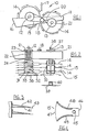
- a rotary mower 10 comprising a support frame 11 in which one, and preferably a pair of shafts 12 and 13 are mounted so as to rotate about substantially vertical and parallel axes.
- Mounted for rotation with each of the shafts 12 and 13 are a plurality of cutting members 15, the cutting members 15 preferably mounted on a plurality of disc members 14 which are fixed to the shafts 12 and 13 for rotation therewith.
- the cutting members 15 are mounted on the disc members 14 so as to project beyond the peripheries thereof and rotate in substantially horizontal planes.
- the cutting members sever plant growth extending up from the ground over which the apparatus is displaced when in use.
- the support frame 11 is preferably constructed and arranged . for mounting on a prime mover although the principles embodied in the invention could be incorporated in a "stand-alone" rotary mower.
- the prime mover is typically a common farm tractor and to this end the support frame 11 preferably includes suitable brackets (not shown) on the inner end 16 thereof whereby the apparatus may be mounted on the three point linkage of the tractor.
- Intermediate linkages may further be provided between the support frame 11 and the three point linkage of the tractor to allow for adjustment of the position of the apparatus or displacement of the apparatus with respect to the prime mover.
- the shaft 12 is preferably mounted ahead of the shaft 13 when viewed with respect to the direction of travel of the apparatus which is indicated by arrow 17.
- This arrangement allows the outer tips of the cutting members 15 mounted on discs 14 attached to the shaft 13 to be set in behind the cutting members mounted on the discs attached to the shaft 12 and thereby ensure that a single cut path is provided upon displacement of the apparatus.
- the shafts 12 and 13 contra rotate with respect to one another and suitable drive means is provided to impart rotation to the shafts 12 and 13.
- a single hydraulic motor 18 is provided which rotates in a clockwise direction as shown in fig 1.
- the hydraulic motor 18 is supplied with fluid under pressure from a pump (not shown) preferably driven from the tractor power-take-off and drive is imparted to shaft 12 through endless belt 19 while shaft 13 is driven from a further crossed over belt 20.
- Drive pulleys 21 keyed or otherwise fixed to the shafts 12 and 13 receive the drive from the motor 18 through the belts 19 and 20 and transmit the drive to the shafts 12 and 13.
- the motor 18 could be replaced by a mechanical drive pick-up and rotated through a suitable linkage or transmission from the power-take-over of the prime mover.
- one hydraulic motor could be provided for each rotating shaft. The motor would preferably be mounted on top of the shafts 12 and 13 so that the motor drives were directly coupled to the shafts 12 and 13. The motor bodies would be retained in sliding guides for the reasons hereinafter appearing.
- the pulleys 21 are incorporated in a suitable drive means which not only imparts rotation to each of the shafts 12 and 13 but also, preferably allows the shafts to float axially. As can be seen the pulleys 21 are mounted on the upper ends of spindles 22 which project downwardly and surround the shafts 12 and 13. The spindles 22 are, in turn, mounted in bearings 23 which are located in tubular mounts 24 fixed to the support frame 11.
- each of the spindles 22 is preferably splined and the outer surface of each of the shafts 12 and 13 is preferably provided with a corresponding spline so that the shafts 12 and 13 are axially slidable within the spindles 22 and may thus float within the spindles 22 while being rotated thereby.
- each shaft 12 and 13 mounted on the lower end of each shaft 12 and 13 is a tubular hub 30 and the disc members 14 which carry the cutting members 15 are mounted on the outer periphery of the hub 30 although it will be appreciated that the cutting members 15 could be mounted directly on the hub 30.
- the disc members 14 each have a central sleeve 31 which forms the mounting point therefor, the sleeve 31 engaging about the hub 30 and being held thereto by locking means 32.
- the locking means 32 and the sleeves 31 are preferably constructed and arranged so that the angular positions of the discs 14 can be adjusted about the periphery of the hubs 30. In this manner the angular positions of the cutting members 15 about the peripheries of the hubs 30 can be adjusted and thus, when viewed vertically as in fig 1, the positions of the cutting members on the various discs can be staggered. This is preferably achieved by providing the sleeves 31 with peripherally extending slots 35 and providing the locking means 32 in the form of clamping bolts which pass through the slots 35 and engage in threaded holes provided on the hubs 30.
- the discs 14 are mounted so that the cutting members 15 on the uppermost disc comprise the leading cutting members, the cutting members trailing sequentially from top to bottom so that plant growth being cut by a rotary mower according to the invention is first cut by the cutting members on the upper discs then those on the next disc down and so on, the final cut being made by the cutting members on the lowermost disc.
- each of the shafts 12 and 13 is determined by a float limiting member 37 mounted on the upper end of each of the shafts 12 and 13 and when this float limiting member 37 engages the upper surface of the drive pulleys 21 no further downward displacement can occur.
- the float limiting member 37 is preferably held in place by a locking nut 38 and by removing the nut 38 the shaft can be withdrawn from its spindle for servicing of the cutting members 15 and/or discs 14.
- each of the shafts 12 and 13 is a skid member 39 which is preferably freely rotatable, through bearings 40, on the bottom of its respective shaft.
- a locating nut (not shown) holds the skid member 39 in place on its respective shaft.
- disc members 14 are preferably shown in the form of flat circular plate members, in practice some degree of curvature will preferably be provided to impart strength to the disc and minimize distortion thereof.
- the discs may be fabricated rather than being formed from a single plate and such an embodiment of disc is shown in fig 3.
- the disc comprises a lower plate member 41 and an upper plate member 42 the two plate members, in combination, defining a composite disc-like unit having a rotating triangular cross section.
- the cutting members 43 are mounted on the composite unit so as to project beyond the periphery thereof in the same manner as described above.
- each of the cutting members has a single aperture 45 whereby the cutting member may be mounted onto the disc 15.
- the mounting is preferably such that the cutting member can pivot about the axis of aperture 45 and it will be noted that the aperture 45 is positioned closer to the inner end of the cutting member so as to ensure that, in operation, the tip is held outwardly by centrifugal force.
- the cutting member 15 has a root 46, a tip 47, a leading edge 48 and a trailing edge 49. It will be noted that when viewed with respect to a line 50 passing radially through the centre of rotation the leading edge 48 at the tip 47 lies ahead of the leading edge at the root. Further, the trailing edge of the tip preferably lies rearwardly of the trailing edge at the root and, as can be seen, the blade 15 is preferably symmetrical about its central axis. Thus, when the leading edge 48 wears, the blade can be removed and inverted so that the trailing edge then becomes the leading edge.
- the blade as shown is preferably formed from a planar material such as sheet spring steel and is mounted so as to make edgewise engagement with growth extending up from the ground.
- the blade is also preferably mounted so as to be rotatable about the axis of mounting aperture 45.
- the apparatus as above described has been devised particularly for providing a rotary mower for cutting grass or other forage crop to short lengths e.g. 50cm. To this end a satisfactory result is achieved using discs of about 750mm diameter spaced at centres of about 100mm.
- the cutting of grass and forage crops to short lengths provides material which dries faster, requires less power to silerate, packs more tightly into transport bins and all this means that less time and power is required to harvest crops.
- the cutting of the grass into short lengths also reduces the drag of long material and minimizes the wrapping of long material about the cutting shafts.
- each drum can follow the ground contour independently of each other which eliminates missed areas and greatly reduces scalping, shock loading and drag.
- the present invention provides a simple yet effective form of rotary mower which is particularly suitable for the cutting of grass and other forage crops.
Landscapes
- Life Sciences & Earth Sciences (AREA)
- Environmental Sciences (AREA)
- Harvester Elements (AREA)
Applications Claiming Priority (2)
| Application Number | Priority Date | Filing Date | Title |
|---|---|---|---|
| NZ206618 | 1983-12-19 | ||
| NZ20661883 | 1983-12-19 |
Publications (1)
| Publication Number | Publication Date |
|---|---|
| EP0146364A1 true EP0146364A1 (fr) | 1985-06-26 |
Family
ID=19920620
Family Applications (2)
| Application Number | Title | Priority Date | Filing Date |
|---|---|---|---|
| EP84308755A Withdrawn EP0146366A3 (fr) | 1983-12-19 | 1984-12-14 | Faucheuse à organes rotatifs |
| EP84308753A Withdrawn EP0146364A1 (fr) | 1983-12-19 | 1984-12-14 | Faucheuse à organes rotatifs |
Family Applications Before (1)
| Application Number | Title | Priority Date | Filing Date |
|---|---|---|---|
| EP84308755A Withdrawn EP0146366A3 (fr) | 1983-12-19 | 1984-12-14 | Faucheuse à organes rotatifs |
Country Status (2)
| Country | Link |
|---|---|
| EP (2) | EP0146366A3 (fr) |
| AU (2) | AU3667184A (fr) |
Cited By (4)
| Publication number | Priority date | Publication date | Assignee | Title |
|---|---|---|---|---|
| EP0202957A1 (fr) * | 1985-05-24 | 1986-11-26 | Neville William Jennings | Lames détachables pour faucheuses à tambour |
| GB2245472A (en) * | 1990-07-04 | 1992-01-08 | Zipfinger Erwin | Mowing or chopping machine |
| RU2528009C1 (ru) * | 2013-01-29 | 2014-09-10 | Федеральное государственное бюджетное образовательное учреждение высшего профессионального образования "Челябинская государственная агроинженерная академия" (ФГБОУ ВПО ЧГАА) | Роторное устройство для скашивания и измельчения ботвы овощных культур |
| RU2551569C1 (ru) * | 2014-01-31 | 2015-05-27 | Федеральное государственное бюджетное образовательное учреждение высшего профессионального образования "Тамбовский государственный технический университет" ФГБОУ ВПО ТГТУ | Косилка-измельчитель сидеральных культур |
Families Citing this family (1)
| Publication number | Priority date | Publication date | Assignee | Title |
|---|---|---|---|---|
| FR2592548A1 (fr) * | 1986-01-09 | 1987-07-10 | Chatut Rene | Dispositif de lame fleau courbee et profilee, pour debroussailleuse. |
Citations (7)
| Publication number | Priority date | Publication date | Assignee | Title |
|---|---|---|---|---|
| US1775520A (en) * | 1927-08-08 | 1930-09-09 | Hugh H Gardner | Stalk cutter |
| US1901310A (en) * | 1932-09-03 | 1933-03-14 | Lewis William Julius | Stalk-cutting machine |
| FR2001453A1 (fr) * | 1968-02-07 | 1969-09-26 | Fahr Ag Maschf | |
| FR1585453A (fr) * | 1968-07-31 | 1970-01-23 | ||
| DE1582249A1 (de) * | 1967-11-04 | 1970-07-30 | Hagedorn Geb & Co | Kreiselmaeher mit Zusatzwerkzeugen |
| FR2221065A1 (fr) * | 1973-03-14 | 1974-10-11 | Lely Nv C Van Der | |
| AU520139B2 (en) * | 1977-06-23 | 1982-01-14 | Leon George Mcleod | Agriculture slasher |
Family Cites Families (5)
| Publication number | Priority date | Publication date | Assignee | Title |
|---|---|---|---|---|
| US2681536A (en) * | 1953-02-25 | 1954-06-22 | Ford Motor Co | Stalk shredder and adjusting mechanism therefor |
| DE1582248A1 (de) * | 1967-10-21 | 1970-07-30 | Hagedorn Geb & Co | Kreiselmaeher |
| DE1782238A1 (de) * | 1968-08-02 | 1971-07-22 | Ernst Weichel | Trommel- oder Scheibenmahlwerk |
| DE2338593A1 (de) * | 1973-07-30 | 1975-02-13 | Niedersachsen Werk Friedrich K | Maehmaschine |
| US4397136A (en) * | 1979-03-09 | 1983-08-09 | Mcleod Leon G | Agricultural slasher |
-
1984
- 1984-12-14 EP EP84308755A patent/EP0146366A3/fr not_active Withdrawn
- 1984-12-14 EP EP84308753A patent/EP0146364A1/fr not_active Withdrawn
- 1984-12-14 AU AU36671/84A patent/AU3667184A/en not_active Abandoned
- 1984-12-14 AU AU36672/84A patent/AU3667284A/en not_active Abandoned
Patent Citations (7)
| Publication number | Priority date | Publication date | Assignee | Title |
|---|---|---|---|---|
| US1775520A (en) * | 1927-08-08 | 1930-09-09 | Hugh H Gardner | Stalk cutter |
| US1901310A (en) * | 1932-09-03 | 1933-03-14 | Lewis William Julius | Stalk-cutting machine |
| DE1582249A1 (de) * | 1967-11-04 | 1970-07-30 | Hagedorn Geb & Co | Kreiselmaeher mit Zusatzwerkzeugen |
| FR2001453A1 (fr) * | 1968-02-07 | 1969-09-26 | Fahr Ag Maschf | |
| FR1585453A (fr) * | 1968-07-31 | 1970-01-23 | ||
| FR2221065A1 (fr) * | 1973-03-14 | 1974-10-11 | Lely Nv C Van Der | |
| AU520139B2 (en) * | 1977-06-23 | 1982-01-14 | Leon George Mcleod | Agriculture slasher |
Cited By (4)
| Publication number | Priority date | Publication date | Assignee | Title |
|---|---|---|---|---|
| EP0202957A1 (fr) * | 1985-05-24 | 1986-11-26 | Neville William Jennings | Lames détachables pour faucheuses à tambour |
| GB2245472A (en) * | 1990-07-04 | 1992-01-08 | Zipfinger Erwin | Mowing or chopping machine |
| RU2528009C1 (ru) * | 2013-01-29 | 2014-09-10 | Федеральное государственное бюджетное образовательное учреждение высшего профессионального образования "Челябинская государственная агроинженерная академия" (ФГБОУ ВПО ЧГАА) | Роторное устройство для скашивания и измельчения ботвы овощных культур |
| RU2551569C1 (ru) * | 2014-01-31 | 2015-05-27 | Федеральное государственное бюджетное образовательное учреждение высшего профессионального образования "Тамбовский государственный технический университет" ФГБОУ ВПО ТГТУ | Косилка-измельчитель сидеральных культур |
Also Published As
| Publication number | Publication date |
|---|---|
| AU3667184A (en) | 1985-06-27 |
| EP0146366A3 (fr) | 1985-07-31 |
| EP0146366A2 (fr) | 1985-06-26 |
| AU3667284A (en) | 1985-06-27 |
Similar Documents
| Publication | Publication Date | Title |
|---|---|---|
| US4537262A (en) | Soil cultivation | |
| US5330114A (en) | Shredder attachment for combine corn head | |
| US4114353A (en) | Terrain traversing device having impeller means for propelling grass clippings and leaves into a receptacle | |
| US3117633A (en) | Lawn treating machines | |
| MXPA00012949A (es) | Carretes de segadora con corte mejorado. | |
| JPS639806B2 (fr) | ||
| US4450673A (en) | Mulching mower | |
| JPH09509823A (ja) | 切断工具 | |
| US4459796A (en) | Gathering plant trash | |
| US6212864B1 (en) | Narrow row cotton harvester | |
| US4304088A (en) | Rotary mower with end-to-end connected blade-carrier supports | |
| US4211060A (en) | Mowing rotor | |
| US3418790A (en) | Rotary cutters with equal angular velocities | |
| EP0146364A1 (fr) | Faucheuse à organes rotatifs | |
| US1442032A (en) | Bottom-cutting and trash-impelling means | |
| US3919830A (en) | Row crop attachment for forage harvesters | |
| US4267686A (en) | Lawn mower having flexible filament cutter elements | |
| TWI224493B (en) | Rotary plant mowing apparatus | |
| US5287932A (en) | Soil tilling device | |
| CN111432627B (zh) | 用于收割机械的辊和辊组、收割机械以及割台 | |
| IE49958B1 (en) | A device for mowing and crushing crops | |
| US3945177A (en) | Method and apparatus for cutting sugar cane | |
| HU221260B1 (en) | Harvester | |
| CN105917855A (zh) | 一种割断喂入装置 | |
| US4478027A (en) | Mower-conditioner |
Legal Events
| Date | Code | Title | Description |
|---|---|---|---|
| PUAI | Public reference made under article 153(3) epc to a published international application that has entered the european phase |
Free format text: ORIGINAL CODE: 0009012 |
|
| AK | Designated contracting states |
Designated state(s): BE DE FR GB IT NL SE |
|
| STAA | Information on the status of an ep patent application or granted ep patent |
Free format text: STATUS: THE APPLICATION IS DEEMED TO BE WITHDRAWN |
|
| 18D | Application deemed to be withdrawn |
Effective date: 19860128 |