EP0145343B1 - Verfahren zum Testen von optischen Fasern und Apparat zur Ausführung des Verfahrens - Google Patents
Verfahren zum Testen von optischen Fasern und Apparat zur Ausführung des Verfahrens Download PDFInfo
- Publication number
- EP0145343B1 EP0145343B1 EP84307986A EP84307986A EP0145343B1 EP 0145343 B1 EP0145343 B1 EP 0145343B1 EP 84307986 A EP84307986 A EP 84307986A EP 84307986 A EP84307986 A EP 84307986A EP 0145343 B1 EP0145343 B1 EP 0145343B1
- Authority
- EP
- European Patent Office
- Prior art keywords
- fibre
- optical
- light
- losses
- measuring
- Prior art date
- Legal status (The legal status is an assumption and is not a legal conclusion. Google has not performed a legal analysis and makes no representation as to the accuracy of the status listed.)
- Expired
Links
Images


Classifications
-
- G—PHYSICS
- G01—MEASURING; TESTING
- G01M—TESTING STATIC OR DYNAMIC BALANCE OF MACHINES OR STRUCTURES; TESTING OF STRUCTURES OR APPARATUS, NOT OTHERWISE PROVIDED FOR
- G01M11/00—Testing of optical apparatus; Testing structures by optical methods not otherwise provided for
- G01M11/08—Testing mechanical properties
- G01M11/088—Testing mechanical properties of optical fibres; Mechanical features associated with the optical testing of optical fibres
Definitions
- This invention relates to a method of, and apparatus for, measurement of optical losses by means of a test fibre.
- Two methods of optical loss measurement represent the state of the art, the methods being the cutback method in which optical losses are assessed by comparing the power received on the launching side of a testfibre with the power received on the output end face of the fibre, and the back-scatter method in which optical losses are assessed by measuring the backscatter from an optical signal which is propagating within the fibre, the backscatter being due to Rayleigh scattering and the backscattered energy propagating in the direction of the fibre input end.
- the cutback method comprises, as shown in Fig. 1, the steps of launching an optical signal from an optical source 2 onto one of the end faces of an exciting fibre 1, connecting a test optical fibre 3 to the other end of the exciting fibre at point A, detecting the optical signal at the other end face of the test fibre 3 by means of an optical detector 4, cutting the optical test fibre 3 at a point B which is several metres from the connection point A, detecting the optical signal at the point B, and comparing the optical powers received at both points to calculate optical losses.
- the optical test fibre 3 is cut in order to measure the optical power coupled to it and to exclude the loss at the connection point A.
- the method involves the complication of cutting and connecting the exciting optical fibre 1 with the test optical fibre 3.
- a further drawback of the cutback method is that the cost for test at manufacturing plants is increased by the need to cut the optical fiber by several metres, that is, the length equal to the distance from the point A to the point B, every time an optical fibre is tested, leading to higher product prices.
- the backscatter method comprises the steps of launching an optical signal directly onto an end face of a test optical fibre 3 from an optical source 2 using a high output pulse semiconductor laser, separating, by means of a directional coupler 6, the backscattered light which is generated in the test optical fibre and which propagates in the direction of the input end of the fibre, and measuring the backscattered light with an optical detector 4.
- This back scatter method is less complicated than the cutback method and does not destroy the optical fibre in testing.
- the backscatter method does, however, require a directional coupler 6 and other optical components for separating the input light.
- the backscatter method involves more sophisticated techniques and optical and electric components, because, in the method, weak backscattered light is received by an optical detector 4 using APD, processed in an averages 7 in order to separate noise from the signal and displayed by a display 8.
- the need for sophisticated techniques and equipment is reflected in the price of any product dependent on the backscatter method of testing.
- patent specification GB-A-1 538 195 discloses a method of detecting light energy in a leakage mode radiated from a fibre into which the light energy may be launched by illuminating a straight portion of the fibre or by illiminating a portion of the fibre formed into a curve of large radius. Such an operation concentrates the light energy in the fibre cladding and would be unsuitable for loss measurements which require the light energy concentrated in the fibre core.
- An objection of the present invention is the provision of a method, simpler than previously known methods, for measuring optical losses in a test fibre, and apparatus for performing the method of measurement.
- a method of measuring the losses of an optical fibre by launching light into the fibre, detecting the power levels of light travelling along the fibre at two points along the fibre, and calculating the losses L from the equation where P 1 and P 2 are the power levels of the light detected at the two points along the fibre, is characterised in that the light is launched into the core of the fibre by bending the fibre, restorably, close to one of its ends with a radius of substantially no more than 3 mm and illuminating the fibre at the bend, and the optical power loss is calculated from the power levels of the light detected at the ends of the fibre.
- the bent portion may be covered by means having an inner surface of light scattering material, in order to obtain more even distribution of the optical signals from the bent portion in both directions.
- the bent portion and the optical source may be enclosed by means having an inner surface of light reflecting material, in order to improve the coupling efficiency between the signal source and the optical fibre.
- Apparatus for measuring the losses of an optical fibre includes a light source for launching light into the fibre and meams for detecting the power levels of the light, travelling along the fibre, at two points along the fibre, characterised in that the apparatus includes means for producing a removable bend in the fibre, close to one of its ends, with a radius of substantially no more than 3 mm in the vicinity of the light source so as to launch light into the core of the fibre, and means arranged to detect the power levels of the light reaching the ends of the fibre.
- the means for producing a removable bend in the fibre may be a sheath structure arranged to enclose the fibre at or near the bend or a pin around which the fibre is wrapped.
- This invention enables the launching of an optical signal into an optical fibre, which may be a coated fibre, and the measurement of the losses of an optical fibre by means of apparatus including an optical source and a power meter, without the need to cut or otherwise damage the fibre, and reduces the number of steps required for performing test measurements.
- the cost of testing at present accounts for a large portion of the price of optical fibres, and if the non-destructive test according to this invention is applied, the cost of testing will be cut by a large margin, thereby improving the economic efficiency of optical communication systems.
- the area near the coupling point which is bent may be covered by means having an inner surface of light scattering material, in order for the coupled light to be distributed uniformly in both directions. Further, the bent portion as well as the optical element may be enclosed by means having an inner surface of light reflecting material so that the signal coupling may have higher efficiency.
- Fig. 3 is a block diagram of an embodiment of the apparatus for performing the method of this invention.
- An optical test fibre 3 is bent slightly to include a small bending radius at a point C and the bent portion is side-illuminated from outside by means of an optical signal from an optical source 2, to cause the propagation of light inside the test fibre 3.
- the light propagates towards both ends through the optical test fibre 3 to be detected by optical detectors 11 and 12. If the optical fibre length between the launching point C and the optical detector 11 is made sufficiently shorter than the length between the point C and the optical detector 12, the optical loss between the point C and the detector 11 may be ignored. If the optical power measured by the detector 11 is expressed as P 1 and the optical power measured by the optical detector 12 as P 2 , the optical loss L may be approximated.
- the losses in the two fibre sections are given by where P 1 and P 2 are output optical powers measured at the ends of the fibre and P o the power at the coupling point. If the fibre length (L 1 ) is short, and therefore the loss (Loss,) in the short fibre section is negligibly small compared with the loss (Loss 2 ) in the long fibre section, then the fibre loss L is easily calculated from (1) and (2) as As shown by the equation (3), the fibre loss measured by the method of the present invention does not depend on the absolute power of the light source and, therefore, precise power control of the light source is not necessary.
- Fig. 4 is a perspective view representation of measurement apparatus for performing tests according to this invention.
- An optical source 2 a lens system 13 and a pin 14 are arranged on a stable and solid mount table.
- the optical source 2 is arranged in a manner such that the output light from the source 2 is slightly defocussed by the lens system 13 before illuminating the neck of the pin 14.
- An optical test fibre 3 is bent around the neck of the pin 14 in the shape of the letter U.
- the distance between the pin 14 and the optical detector 11 is 2 m.
- the pin 14 is provided with a spring structure 15 which holds the optical fibre 3 onto the neck portion of the pin 14. Pins having necks of various diameters are available for varying the curvature of the bend.
- the optical source 2 is an He-Ne laser device with an output of 5 mW.
- Model No. GLS 2027 manufactured by NEC was used.
- Optical power meters were used as the optical detectors 11, 12.
- the lens system 13 has a magnifying power of 20 folds and the distance between the lens 13 and the pin 14 is about 20 mm.
- the laser beam from the test optical source 2 is expanded to about 4 mm width to illuminate the bent portion of the optical test fibre 3.
- the optical test fibre 3 may be, for example, a GI profile fibre having a core diameter of 50 pm, and a cladding outer diameter of 125 pm.
- the optical fibre 3 also has a cushion layer placed upon the cladding comprising silicone resin coated with polyethylene. The outer diameter of the cushion layer is 400 pm.
- Fig. 5 shows the relation between the curvature of the bend at the launching point C and the coupled optical power which is obtained by means of the apparatus of Fig. 4. More specifically, the graph shows the values of optical power measured by a detector 11 when the curvature of the bent position of a test fibre at the launching point C is changed and an optical signal propagates 2 m within the fibre 3.
- the coupling efficiency (dB) is plotted along the right-hand axis assuming the output from the optical source 2 is 5 mW.
- the graph indicates that the coupling efficiency increases significantly if the bending radius is 3 mm or less.
- the inlet optical power is approximately -55 dBm.
- the minimum power level of a high sensitivity power meter is -90 dBm, the meter has an excess dynamic range of 35 dB.
- Fig. 6 is a graph showing the coupling efficiency obtained in tests on samples with different coatings. Using the same test apparatus, the coupling efficiency was measured. The results show that this invention may be applied not only to UV- curable resin coating and silicone coated fibre but also to polyethylene coated fibres. The bending radius was 2 mm for both tests.
- a sample of an optical test fibre was bent to have the curvature radius of 2 mm, and the fibre was straightened to recover the original shape. There was not damage nor traces of bending after straightening. An optical signal was passed through the restored portion to confirm that no change had occurred in the behaviour of the fibre following bending.
- Fig. 7 shows the result of a test which was conducted to confirm that optical signals of almost similar power were propagated from the launching point C through a test optical fibre in both directions on the system shown in Fig. 3.
- the distances from the launching point C to the detectors 11 and 12 were both made 2m, and the differences in the optical powers detected by both detectors were measured.
- 50 optical fibres of silicone coated with polyethylene were prepared, each of the fibres was mounted once on the test apparatus described above and the frequency distribution was examined.
- the result of the test is shown in Fig. 7.
- the graph indicates that the average difference in the power of the optical signals propagating in opposite directions is -0.1 dB although there is deviation of about ⁇ 2 dB. If enough measurements are performed to obtain an average, it may be assumed that similar power levels are propagated in each direction towards the ends of the optical test fibre.
- Fig. 9 shows the relation between the lateral force and the loss increase when the bending radius of an optical test fibre at the launching point is increased.
- the symbol 0 indicates when the bending radius is 13 mm
- A indicates a 5 mm radius
- 0 indicates a 2 mm radius
- 0 indicates the conventional stationary mode condition obtained in a dummy fibre.
- the loss increase is significant as lateral force increases.
- the excitation state is not the stationary mode distribution.
- the result is substantially similar to that when excitation is carried through a dummy fibre. This may be because the light excited in higher mode is radiated simultaneously.
- the above tests establish that if the bending radius is set close to 2 mm, not only is the coupling efficiency enhanced but also the loss is measured in a mode similar to the stationary mode realized with the dummy excitation method.
- the dummy excitation method which is the most popular method for loss evaluation, is performed by the method of the present invention, but the method may be applied to other excitations by an appropriate change in the bending radius.
- the method of the present invention is most useful for the case where an optical fibre is directly excited by means of a laser diode.
- Figs. 10 and 11 The losses measured under the above conditions by the method of the invention are illustrated by Figs. 10 and 11.
- the length of the optical fibre on the shorter section was made equal to 2 m for both cases and the bending radius at the launching point was 2 mm.
- the measurement was taken 50 times.
- Fig. 10 is a histogram of the loss values of a silicone coated fibre (1.5 km long)
- Fig. 11 is a histogram showing the loss values of a polyethylene coated fibre (0.45 km long), for the conditions set out above, measured by this method.
- the mean loss measured by this method is 9.2 dB.
- the losses for the same sample, measured by the prior art cutback method is 9.1 dB.
- the loss values, according to this method average 3.9 dB, and the loss values measured by the cutback method average 3.8 dB.
- Fig. 12 is a perspective view of a further arrangement of the apparatus for bending an optical fibre. As shown in Fig. 12, a portion of an optical fibre 3 at about 2 m from an end of the optical fibre is bent and inserted into a sheath structure 18.
- Measurement is carried out simply and stably by the use of the sheath structure.
- the sheath structure 18 of Fig. 12 may be used to investigate the effects of varying the focussing of the light illuminating an optical fibre.
- An optical signal which illuminates the test optical fibre 3 is slightly defocussed by the lens system 13. Although the optical power coupled in the test fibre 3 became smaller, the optical power assumes stable values without much deviation.
- the structure shown in Fig. 12 is used to maintain a bend in a fibre at a position 450 m away from an optical detector 12. Optical power is measured with the detector 12 by moving the bending position by 4 cm once every 1 m for the total of 25 times. The result is shown in Fig. 13.
- Fig. 13A shows the result of measurement where the light output from a laser device illuminated an optical test fibre 3 without using the lens system 13.
- Fig. 13A shows the result of measurement where the light output from a laser device illuminated an optical test fibre 3 without using the lens system 13.
- FIG. 13B shows the result of a measurement using the lens system 13 where the distance from the lens system 13 to the bent portion was set at about 20 mm and the laser beam was expanded to about 4 mm for illumination.
- the average value is 64.9 dB and the standard deviation is 1.04 dB in Fig. 13A.
- the average value is 71.1 dB and the standard deviation is 0.57 dB in Fig. 13B.
- Fig. 14 shows the portion critical for coupling, of an apparatus for performing the method of this invention, wherein a bend is formed at the portion C of an optical test fibre and the portion is placed in a container 23.
- An optical source 2 is attached inside the container 23.
- the unique feature of this structure lies inside the container 23.
- the inside of the container 23 comprises light scattering material, for example, white paint. It may not be white but may be any paint which does not absorb energy at the wavelength of the optical signal but absorbs energy at other wavelengths. It may be a mirror the surface of which is opaque.
- the optical signal does not leak out of the container 23 but repeats diffused reflections within the container 23 and is thus contained therein. This enables uniformly illumination of the bent portion C to couple the optical signal into the fibre 3 equally in both directions at an excellent coupling efficiency.
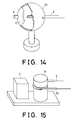
- Fig. 15 is a perspective view of another arrangement for performing the method of the present invention.
- the optical fibre 3 is bent around a pin 14 and an optical signal illuminates the bent portion from a source 2.
- the optical fibre 3 is covered by a tube 25 made of a light scattering material, for example, a transparent tube the surface of which is made opaque or a transparent tube containing a large number of fine particles which scatter light.
- the light illuminating the tube 25 is scattered to reach the optical fibre 3, which is, therefore, uniformly illuminated over the portion covered by the tube 25.
- the light may be coupled into the fibre 3 at a high efficiency.
- Fig. 16 shows another arrangement for performing the method of the present invention.
- the bent portion of the fibre 3 is covered by two reflecting members 26, 27 so that the optical signal starting from the source 2 is reflected repeatedly, as shown by arrows in the figure, to illuminate the fibre 3.
- This structure enables the optical signal to illuminate evenly a desired length of the fibre without becoming concentrated on a particular portion and the optical signal coupled into the fibre 3 becomes uniform in both directions.
- the coupled optical power is increased as the fibre is illuminated repeatedly.
- Fig. 17 shows another arrangement for performing the method of the present invention.
- An optical test fibre 3 is wound around a pin 14 several times in this arrangement which is otherwise the same as the one shown in Fig. 14. In this arrangement, the effective length of the bent portion is large and the coupling efficiency is high.
Claims (10)
Applications Claiming Priority (4)
| Application Number | Priority Date | Filing Date | Title |
|---|---|---|---|
| JP217458/83 | 1983-11-18 | ||
| JP58217458A JPS60108727A (ja) | 1983-11-18 | 1983-11-18 | 光フアイバの光損失特性測定方法および装置 |
| JP77848/84 | 1984-04-18 | ||
| JP59077848A JPS60221712A (ja) | 1984-04-18 | 1984-04-18 | 光フアイバと光信号素子との結合方法 |
Publications (3)
| Publication Number | Publication Date |
|---|---|
| EP0145343A2 EP0145343A2 (de) | 1985-06-19 |
| EP0145343A3 EP0145343A3 (en) | 1985-08-28 |
| EP0145343B1 true EP0145343B1 (de) | 1988-05-18 |
Family
ID=26418901
Family Applications (1)
| Application Number | Title | Priority Date | Filing Date |
|---|---|---|---|
| EP84307986A Expired EP0145343B1 (de) | 1983-11-18 | 1984-11-16 | Verfahren zum Testen von optischen Fasern und Apparat zur Ausführung des Verfahrens |
Country Status (2)
| Country | Link |
|---|---|
| US (1) | US4659215A (de) |
| EP (1) | EP0145343B1 (de) |
Families Citing this family (17)
| Publication number | Priority date | Publication date | Assignee | Title |
|---|---|---|---|---|
| US4883054A (en) * | 1987-12-09 | 1989-11-28 | Fuller Research Corporation | Optical fiber break detector |
| US4890915A (en) * | 1988-08-16 | 1990-01-02 | The United States Of America As Represented By The Administrator Of The National Aeronautics And Space Administration | Method and apparatus for determining optical absorption and emission characteristics of a crystal or non-crystalline fiber |
| US4936675A (en) * | 1989-05-14 | 1990-06-26 | The United States Of America As Represented By The Secretary Of The Navy | Calibrated bender for fiber optic cable position determination |
| US4996420A (en) * | 1989-10-05 | 1991-02-26 | Hughes Aircraft Company | Measurement of optical attenuation along the length of bent optical fibers |
| GB9012063D0 (en) * | 1990-05-30 | 1990-07-18 | Bicc Plc | Optical fibre measurement |
| IL102091A (en) * | 1992-06-03 | 1996-03-31 | Israel State | A method of measuring the sensitivity to bending of optical fibers |
| US5357332A (en) * | 1992-08-11 | 1994-10-18 | Photonix Industries | Apparatus for, and method of, determining the effectiveness of a splice of optical fiber |
| US5673351A (en) * | 1993-03-18 | 1997-09-30 | Telstra Corporation Limited | Method and apparatus for inducing a temporary localized transmission loss in a telecommunications cable |
| US5825516A (en) * | 1996-07-25 | 1998-10-20 | Hewlett-Packard Company | Optical power meter for detecting loss factors in fiber optic communications |
| WO2001069734A1 (en) | 2000-03-10 | 2001-09-20 | Corning Incorporated | Optical fiber with absorbing overclad glass layer |
| US6393923B1 (en) * | 2001-04-30 | 2002-05-28 | The United States Of America As Represented By The Secretary Of The Army | Dynamic bendloss measuring device |
| US7473906B2 (en) | 2005-04-28 | 2009-01-06 | Claudio Oliveira Egalon | Reversible, low cost, distributed optical fiber sensor with high spatial resolution |
| US8463083B2 (en) * | 2009-01-30 | 2013-06-11 | Claudio Oliveira Egalon | Side illuminated multi point multi parameter optical fiber sensor |
| WO2010094604A1 (en) * | 2009-02-20 | 2010-08-26 | Tyco Electronics Raychem Bvba | Optical fibre network test device |
| CN103616160A (zh) * | 2013-11-27 | 2014-03-05 | 国家电网公司 | 光纤保护通道在线监测系统 |
| CN109596322A (zh) * | 2018-12-28 | 2019-04-09 | 中天科技光纤有限公司 | 测试工装、测试系统及其使用方法 |
| CN115266044B (zh) * | 2022-09-23 | 2022-12-23 | 国网湖北省电力有限公司 | 一种光电测试治具及其预警方法 |
Family Cites Families (4)
| Publication number | Priority date | Publication date | Assignee | Title |
|---|---|---|---|---|
| GB1538195A (en) * | 1974-11-08 | 1979-01-10 | Plessey Co Ltd | Method and apparatus for detecting light radiated from or propogating light into optical fibres |
| US4183666A (en) * | 1977-03-10 | 1980-01-15 | Mitsubishi Rayon Company, Limited | Method of measuring light transmission losses of optical materials |
| US4343532A (en) * | 1980-06-16 | 1982-08-10 | General Dynamics, Pomona Division | Dual directional wavelength demultiplexer |
| JPS58198015A (ja) * | 1982-05-14 | 1983-11-17 | Nippon Telegr & Teleph Corp <Ntt> | 光フアイバ接続損失測定方法 |
-
1984
- 1984-11-16 EP EP84307986A patent/EP0145343B1/de not_active Expired
- 1984-11-19 US US06/672,886 patent/US4659215A/en not_active Expired - Lifetime
Also Published As
| Publication number | Publication date |
|---|---|
| EP0145343A2 (de) | 1985-06-19 |
| EP0145343A3 (en) | 1985-08-28 |
| US4659215A (en) | 1987-04-21 |
Similar Documents
| Publication | Publication Date | Title |
|---|---|---|
| EP0145343B1 (de) | Verfahren zum Testen von optischen Fasern und Apparat zur Ausführung des Verfahrens | |
| CA1135547A (en) | Optical waveguide mode scrambler | |
| US6400450B1 (en) | Method of qualifying a multimode optical fiber for bandwidth performance | |
| US6456370B1 (en) | Method of measuring bending loss with an optical time domain reflectometer | |
| US4779978A (en) | Method of measuring the refractive index profile of optical fibers | |
| US4981338A (en) | Optical fiber refractometer | |
| US4257707A (en) | Device for measuring the attenuation of optical waves on optical transmission paths | |
| EP0926479A1 (de) | Messung optischer Verluste | |
| EP0548935A1 (de) | Vorrichtung zur Bestimmung des effektiven Brechungsindexes von optischen Fasern | |
| US5625450A (en) | Apparatus for measuring connection loss and reflection attenuation of optical fiber cord | |
| US6590642B2 (en) | Apparatus for inspecting fiber with optical connector | |
| JPS59501800A (ja) | 光フアイバの屈折率分布決定のための方法と装置 | |
| US4988863A (en) | Optical fiber refractometer launching light at a non-zero launch angle | |
| JPH0357450B2 (de) | ||
| Hayber | Analytical analysis and experimental validation of optical power estimation in V-grooved polymer optical fibers | |
| EP1496346B1 (de) | Verfahren und Vorrichtung zum Erfassen der Grenzwellenlänge einer optischen Faser | |
| EP0245091A1 (de) | Verfahren und Vorrichtung zum Messen mit Lichtleitfasern | |
| Sumida et al. | A new method of optical fiber loss measurement by the side-illumination technique | |
| JP3388496B2 (ja) | 単一モード光ファイバの特性評価方法 | |
| Neumann et al. | Physical Explanation of Waveguiding by Single-Mode Fibers | |
| JPS627020A (ja) | 光フアイバハイドロホン | |
| Kitayama et al. | Length dependence of LP [sub] 11 [/sub] Mode Cutoff And Its Influence On The Chromatic Dispersion Measurement By Phase Shift Method | |
| JP2511999B2 (ja) | 液体検知用光ファイバおよびこれを用いた液体検知システム | |
| Young et al. | Optical Fiber Measurements | |
| Rourke et al. | Fiber parameter studies with the OTDR |
Legal Events
| Date | Code | Title | Description |
|---|---|---|---|
| PUAI | Public reference made under article 153(3) epc to a published international application that has entered the european phase |
Free format text: ORIGINAL CODE: 0009012 |
|
| AK | Designated contracting states |
Designated state(s): FR GB |
|
| PUAL | Search report despatched |
Free format text: ORIGINAL CODE: 0009013 |
|
| AK | Designated contracting states |
Designated state(s): FR GB |
|
| RAP1 | Party data changed (applicant data changed or rights of an application transferred) |
Owner name: NIPPON TELEGRAPH AND TELEPHONE CORPORATION |
|
| 17P | Request for examination filed |
Effective date: 19851220 |
|
| 17Q | First examination report despatched |
Effective date: 19861215 |
|
| GRAA | (expected) grant |
Free format text: ORIGINAL CODE: 0009210 |
|
| AK | Designated contracting states |
Kind code of ref document: B1 Designated state(s): FR GB |
|
| ET | Fr: translation filed | ||
| PLBE | No opposition filed within time limit |
Free format text: ORIGINAL CODE: 0009261 |
|
| STAA | Information on the status of an ep patent application or granted ep patent |
Free format text: STATUS: NO OPPOSITION FILED WITHIN TIME LIMIT |
|
| 26N | No opposition filed | ||
| REG | Reference to a national code |
Ref country code: FR Ref legal event code: CA |
|
| REG | Reference to a national code |
Ref country code: GB Ref legal event code: IF02 |
|
| PGFP | Annual fee paid to national office [announced via postgrant information from national office to epo] |
Ref country code: FR Payment date: 20031110 Year of fee payment: 20 |
|
| PGFP | Annual fee paid to national office [announced via postgrant information from national office to epo] |
Ref country code: GB Payment date: 20031112 Year of fee payment: 20 |
|
| PG25 | Lapsed in a contracting state [announced via postgrant information from national office to epo] |
Ref country code: GB Free format text: LAPSE BECAUSE OF EXPIRATION OF PROTECTION Effective date: 20041115 |
|
| REG | Reference to a national code |
Ref country code: GB Ref legal event code: PE20 |