EP0145139A2 - Procédé de fabrication d'un assemblage de tube et raccord - Google Patents
Procédé de fabrication d'un assemblage de tube et raccord Download PDFInfo
- Publication number
- EP0145139A2 EP0145139A2 EP19840306261 EP84306261A EP0145139A2 EP 0145139 A2 EP0145139 A2 EP 0145139A2 EP 19840306261 EP19840306261 EP 19840306261 EP 84306261 A EP84306261 A EP 84306261A EP 0145139 A2 EP0145139 A2 EP 0145139A2
- Authority
- EP
- European Patent Office
- Prior art keywords
- fitting
- tube
- collar
- pin
- die
- Prior art date
- Legal status (The legal status is an assumption and is not a legal conclusion. Google has not performed a legal analysis and makes no representation as to the accuracy of the status listed.)
- Granted
Links
Images
Classifications
-
- A—HUMAN NECESSITIES
- A61—MEDICAL OR VETERINARY SCIENCE; HYGIENE
- A61M—DEVICES FOR INTRODUCING MEDIA INTO, OR ONTO, THE BODY; DEVICES FOR TRANSDUCING BODY MEDIA OR FOR TAKING MEDIA FROM THE BODY; DEVICES FOR PRODUCING OR ENDING SLEEP OR STUPOR
- A61M25/00—Catheters; Hollow probes
- A61M25/0009—Making of catheters or other medical or surgical tubes
- A61M25/0014—Connecting a tube to a hub
-
- B—PERFORMING OPERATIONS; TRANSPORTING
- B29—WORKING OF PLASTICS; WORKING OF SUBSTANCES IN A PLASTIC STATE IN GENERAL
- B29C—SHAPING OR JOINING OF PLASTICS; SHAPING OF MATERIAL IN A PLASTIC STATE, NOT OTHERWISE PROVIDED FOR; AFTER-TREATMENT OF THE SHAPED PRODUCTS, e.g. REPAIRING
- B29C57/00—Shaping of tube ends, e.g. flanging, belling or closing; Apparatus therefor, e.g. collapsible mandrels
-
- B—PERFORMING OPERATIONS; TRANSPORTING
- B29—WORKING OF PLASTICS; WORKING OF SUBSTANCES IN A PLASTIC STATE IN GENERAL
- B29C—SHAPING OR JOINING OF PLASTICS; SHAPING OF MATERIAL IN A PLASTIC STATE, NOT OTHERWISE PROVIDED FOR; AFTER-TREATMENT OF THE SHAPED PRODUCTS, e.g. REPAIRING
- B29C65/00—Joining or sealing of preformed parts, e.g. welding of plastics materials; Apparatus therefor
- B29C65/02—Joining or sealing of preformed parts, e.g. welding of plastics materials; Apparatus therefor by heating, with or without pressure
- B29C65/06—Joining or sealing of preformed parts, e.g. welding of plastics materials; Apparatus therefor by heating, with or without pressure using friction, e.g. spin welding
- B29C65/0672—Spin welding
-
- B—PERFORMING OPERATIONS; TRANSPORTING
- B29—WORKING OF PLASTICS; WORKING OF SUBSTANCES IN A PLASTIC STATE IN GENERAL
- B29C—SHAPING OR JOINING OF PLASTICS; SHAPING OF MATERIAL IN A PLASTIC STATE, NOT OTHERWISE PROVIDED FOR; AFTER-TREATMENT OF THE SHAPED PRODUCTS, e.g. REPAIRING
- B29C65/00—Joining or sealing of preformed parts, e.g. welding of plastics materials; Apparatus therefor
- B29C65/56—Joining or sealing of preformed parts, e.g. welding of plastics materials; Apparatus therefor using mechanical means or mechanical connections, e.g. form-fits
- B29C65/565—Joining or sealing of preformed parts, e.g. welding of plastics materials; Apparatus therefor using mechanical means or mechanical connections, e.g. form-fits involving interference fits, e.g. force-fits or press-fits
-
- B—PERFORMING OPERATIONS; TRANSPORTING
- B29—WORKING OF PLASTICS; WORKING OF SUBSTANCES IN A PLASTIC STATE IN GENERAL
- B29C—SHAPING OR JOINING OF PLASTICS; SHAPING OF MATERIAL IN A PLASTIC STATE, NOT OTHERWISE PROVIDED FOR; AFTER-TREATMENT OF THE SHAPED PRODUCTS, e.g. REPAIRING
- B29C66/00—General aspects of processes or apparatus for joining preformed parts
- B29C66/01—General aspects dealing with the joint area or with the area to be joined
- B29C66/05—Particular design of joint configurations
- B29C66/10—Particular design of joint configurations particular design of the joint cross-sections
- B29C66/12—Joint cross-sections combining only two joint-segments; Tongue and groove joints; Tenon and mortise joints; Stepped joint cross-sections
- B29C66/124—Tongue and groove joints
- B29C66/1244—Tongue and groove joints characterised by the male part, i.e. the part comprising the tongue
- B29C66/12441—Tongue and groove joints characterised by the male part, i.e. the part comprising the tongue being a single wall
-
- B—PERFORMING OPERATIONS; TRANSPORTING
- B29—WORKING OF PLASTICS; WORKING OF SUBSTANCES IN A PLASTIC STATE IN GENERAL
- B29C—SHAPING OR JOINING OF PLASTICS; SHAPING OF MATERIAL IN A PLASTIC STATE, NOT OTHERWISE PROVIDED FOR; AFTER-TREATMENT OF THE SHAPED PRODUCTS, e.g. REPAIRING
- B29C66/00—General aspects of processes or apparatus for joining preformed parts
- B29C66/50—General aspects of joining tubular articles; General aspects of joining long products, i.e. bars or profiled elements; General aspects of joining single elements to tubular articles, hollow articles or bars; General aspects of joining several hollow-preforms to form hollow or tubular articles
- B29C66/51—Joining tubular articles, profiled elements or bars; Joining single elements to tubular articles, hollow articles or bars; Joining several hollow-preforms to form hollow or tubular articles
- B29C66/53—Joining single elements to tubular articles, hollow articles or bars
- B29C66/534—Joining single elements to open ends of tubular or hollow articles or to the ends of bars
- B29C66/5344—Joining single elements to open ends of tubular or hollow articles or to the ends of bars said single elements being substantially annular, i.e. of finite length, e.g. joining flanges to tube ends
-
- B—PERFORMING OPERATIONS; TRANSPORTING
- B29—WORKING OF PLASTICS; WORKING OF SUBSTANCES IN A PLASTIC STATE IN GENERAL
- B29C—SHAPING OR JOINING OF PLASTICS; SHAPING OF MATERIAL IN A PLASTIC STATE, NOT OTHERWISE PROVIDED FOR; AFTER-TREATMENT OF THE SHAPED PRODUCTS, e.g. REPAIRING
- B29C66/00—General aspects of processes or apparatus for joining preformed parts
- B29C66/50—General aspects of joining tubular articles; General aspects of joining long products, i.e. bars or profiled elements; General aspects of joining single elements to tubular articles, hollow articles or bars; General aspects of joining several hollow-preforms to form hollow or tubular articles
- B29C66/61—Joining from or joining on the inside
- B29C66/612—Making circumferential joints
-
- B—PERFORMING OPERATIONS; TRANSPORTING
- B29—WORKING OF PLASTICS; WORKING OF SUBSTANCES IN A PLASTIC STATE IN GENERAL
- B29C—SHAPING OR JOINING OF PLASTICS; SHAPING OF MATERIAL IN A PLASTIC STATE, NOT OTHERWISE PROVIDED FOR; AFTER-TREATMENT OF THE SHAPED PRODUCTS, e.g. REPAIRING
- B29C66/00—General aspects of processes or apparatus for joining preformed parts
- B29C66/50—General aspects of joining tubular articles; General aspects of joining long products, i.e. bars or profiled elements; General aspects of joining single elements to tubular articles, hollow articles or bars; General aspects of joining several hollow-preforms to form hollow or tubular articles
- B29C66/63—Internally supporting the article during joining
- B29C66/636—Internally supporting the article during joining using a support which remains in the joined object
-
- B—PERFORMING OPERATIONS; TRANSPORTING
- B29—WORKING OF PLASTICS; WORKING OF SUBSTANCES IN A PLASTIC STATE IN GENERAL
- B29C—SHAPING OR JOINING OF PLASTICS; SHAPING OF MATERIAL IN A PLASTIC STATE, NOT OTHERWISE PROVIDED FOR; AFTER-TREATMENT OF THE SHAPED PRODUCTS, e.g. REPAIRING
- B29C66/00—General aspects of processes or apparatus for joining preformed parts
- B29C66/80—General aspects of machine operations or constructions and parts thereof
- B29C66/82—Pressure application arrangements, e.g. transmission or actuating mechanisms for joining tools or clamps
- B29C66/824—Actuating mechanisms
- B29C66/8242—Pneumatic or hydraulic drives
-
- B—PERFORMING OPERATIONS; TRANSPORTING
- B29—WORKING OF PLASTICS; WORKING OF SUBSTANCES IN A PLASTIC STATE IN GENERAL
- B29C—SHAPING OR JOINING OF PLASTICS; SHAPING OF MATERIAL IN A PLASTIC STATE, NOT OTHERWISE PROVIDED FOR; AFTER-TREATMENT OF THE SHAPED PRODUCTS, e.g. REPAIRING
- B29C66/00—General aspects of processes or apparatus for joining preformed parts
- B29C66/80—General aspects of machine operations or constructions and parts thereof
- B29C66/83—General aspects of machine operations or constructions and parts thereof characterised by the movement of the joining or pressing tools
- B29C66/832—Reciprocating joining or pressing tools
- B29C66/8322—Joining or pressing tools reciprocating along one axis
-
- B—PERFORMING OPERATIONS; TRANSPORTING
- B29—WORKING OF PLASTICS; WORKING OF SUBSTANCES IN A PLASTIC STATE IN GENERAL
- B29C—SHAPING OR JOINING OF PLASTICS; SHAPING OF MATERIAL IN A PLASTIC STATE, NOT OTHERWISE PROVIDED FOR; AFTER-TREATMENT OF THE SHAPED PRODUCTS, e.g. REPAIRING
- B29C66/00—General aspects of processes or apparatus for joining preformed parts
- B29C66/90—Measuring or controlling the joining process
- B29C66/92—Measuring or controlling the joining process by measuring or controlling the pressure, the force, the mechanical power or the displacement of the joining tools
- B29C66/924—Measuring or controlling the joining process by measuring or controlling the pressure, the force, the mechanical power or the displacement of the joining tools by controlling or regulating the pressure, the force, the mechanical power or the displacement of the joining tools
- B29C66/9241—Measuring or controlling the joining process by measuring or controlling the pressure, the force, the mechanical power or the displacement of the joining tools by controlling or regulating the pressure, the force, the mechanical power or the displacement of the joining tools by controlling or regulating the pressure, the force or the mechanical power
-
- B—PERFORMING OPERATIONS; TRANSPORTING
- B29—WORKING OF PLASTICS; WORKING OF SUBSTANCES IN A PLASTIC STATE IN GENERAL
- B29C—SHAPING OR JOINING OF PLASTICS; SHAPING OF MATERIAL IN A PLASTIC STATE, NOT OTHERWISE PROVIDED FOR; AFTER-TREATMENT OF THE SHAPED PRODUCTS, e.g. REPAIRING
- B29C66/00—General aspects of processes or apparatus for joining preformed parts
- B29C66/90—Measuring or controlling the joining process
- B29C66/93—Measuring or controlling the joining process by measuring or controlling the speed
- B29C66/934—Measuring or controlling the joining process by measuring or controlling the speed by controlling or regulating the speed
- B29C66/93451—Measuring or controlling the joining process by measuring or controlling the speed by controlling or regulating the speed by controlling or regulating the rotational speed, i.e. the speed of revolution
-
- B—PERFORMING OPERATIONS; TRANSPORTING
- B29—WORKING OF PLASTICS; WORKING OF SUBSTANCES IN A PLASTIC STATE IN GENERAL
- B29C—SHAPING OR JOINING OF PLASTICS; SHAPING OF MATERIAL IN A PLASTIC STATE, NOT OTHERWISE PROVIDED FOR; AFTER-TREATMENT OF THE SHAPED PRODUCTS, e.g. REPAIRING
- B29C66/00—General aspects of processes or apparatus for joining preformed parts
- B29C66/90—Measuring or controlling the joining process
- B29C66/94—Measuring or controlling the joining process by measuring or controlling the time
- B29C66/944—Measuring or controlling the joining process by measuring or controlling the time by controlling or regulating the time
-
- B—PERFORMING OPERATIONS; TRANSPORTING
- B29—WORKING OF PLASTICS; WORKING OF SUBSTANCES IN A PLASTIC STATE IN GENERAL
- B29C—SHAPING OR JOINING OF PLASTICS; SHAPING OF MATERIAL IN A PLASTIC STATE, NOT OTHERWISE PROVIDED FOR; AFTER-TREATMENT OF THE SHAPED PRODUCTS, e.g. REPAIRING
- B29C66/00—General aspects of processes or apparatus for joining preformed parts
- B29C66/70—General aspects of processes or apparatus for joining preformed parts characterised by the composition, physical properties or the structure of the material of the parts to be joined; Joining with non-plastics material
- B29C66/71—General aspects of processes or apparatus for joining preformed parts characterised by the composition, physical properties or the structure of the material of the parts to be joined; Joining with non-plastics material characterised by the composition of the plastics material of the parts to be joined
-
- B—PERFORMING OPERATIONS; TRANSPORTING
- B29—WORKING OF PLASTICS; WORKING OF SUBSTANCES IN A PLASTIC STATE IN GENERAL
- B29C—SHAPING OR JOINING OF PLASTICS; SHAPING OF MATERIAL IN A PLASTIC STATE, NOT OTHERWISE PROVIDED FOR; AFTER-TREATMENT OF THE SHAPED PRODUCTS, e.g. REPAIRING
- B29C66/00—General aspects of processes or apparatus for joining preformed parts
- B29C66/90—Measuring or controlling the joining process
- B29C66/92—Measuring or controlling the joining process by measuring or controlling the pressure, the force, the mechanical power or the displacement of the joining tools
- B29C66/929—Measuring or controlling the joining process by measuring or controlling the pressure, the force, the mechanical power or the displacement of the joining tools characterized by specific pressure, force, mechanical power or displacement values or ranges
-
- B—PERFORMING OPERATIONS; TRANSPORTING
- B29—WORKING OF PLASTICS; WORKING OF SUBSTANCES IN A PLASTIC STATE IN GENERAL
- B29C—SHAPING OR JOINING OF PLASTICS; SHAPING OF MATERIAL IN A PLASTIC STATE, NOT OTHERWISE PROVIDED FOR; AFTER-TREATMENT OF THE SHAPED PRODUCTS, e.g. REPAIRING
- B29C66/00—General aspects of processes or apparatus for joining preformed parts
- B29C66/90—Measuring or controlling the joining process
- B29C66/93—Measuring or controlling the joining process by measuring or controlling the speed
- B29C66/939—Measuring or controlling the joining process by measuring or controlling the speed characterised by specific speed values or ranges
-
- B—PERFORMING OPERATIONS; TRANSPORTING
- B29—WORKING OF PLASTICS; WORKING OF SUBSTANCES IN A PLASTIC STATE IN GENERAL
- B29C—SHAPING OR JOINING OF PLASTICS; SHAPING OF MATERIAL IN A PLASTIC STATE, NOT OTHERWISE PROVIDED FOR; AFTER-TREATMENT OF THE SHAPED PRODUCTS, e.g. REPAIRING
- B29C66/00—General aspects of processes or apparatus for joining preformed parts
- B29C66/90—Measuring or controlling the joining process
- B29C66/94—Measuring or controlling the joining process by measuring or controlling the time
- B29C66/949—Measuring or controlling the joining process by measuring or controlling the time characterised by specific time values or ranges
-
- B—PERFORMING OPERATIONS; TRANSPORTING
- B29—WORKING OF PLASTICS; WORKING OF SUBSTANCES IN A PLASTIC STATE IN GENERAL
- B29K—INDEXING SCHEME ASSOCIATED WITH SUBCLASSES B29B, B29C OR B29D, RELATING TO MOULDING MATERIALS OR TO MATERIALS FOR MOULDS, REINFORCEMENTS, FILLERS OR PREFORMED PARTS, e.g. INSERTS
- B29K2995/00—Properties of moulding materials, reinforcements, fillers, preformed parts or moulds
- B29K2995/0003—Properties of moulding materials, reinforcements, fillers, preformed parts or moulds having particular electrical or magnetic properties, e.g. piezoelectric
- B29K2995/0011—Electromagnetic wave shielding material
-
- Y—GENERAL TAGGING OF NEW TECHNOLOGICAL DEVELOPMENTS; GENERAL TAGGING OF CROSS-SECTIONAL TECHNOLOGIES SPANNING OVER SEVERAL SECTIONS OF THE IPC; TECHNICAL SUBJECTS COVERED BY FORMER USPC CROSS-REFERENCE ART COLLECTIONS [XRACs] AND DIGESTS
- Y10—TECHNICAL SUBJECTS COVERED BY FORMER USPC
- Y10T—TECHNICAL SUBJECTS COVERED BY FORMER US CLASSIFICATION
- Y10T156/00—Adhesive bonding and miscellaneous chemical manufacture
- Y10T156/10—Methods of surface bonding and/or assembly therefor
- Y10T156/1002—Methods of surface bonding and/or assembly therefor with permanent bending or reshaping or surface deformation of self sustaining lamina
- Y10T156/1005—Methods of surface bonding and/or assembly therefor with permanent bending or reshaping or surface deformation of self sustaining lamina by inward collapsing of portion of hollow body
-
- Y—GENERAL TAGGING OF NEW TECHNOLOGICAL DEVELOPMENTS; GENERAL TAGGING OF CROSS-SECTIONAL TECHNOLOGIES SPANNING OVER SEVERAL SECTIONS OF THE IPC; TECHNICAL SUBJECTS COVERED BY FORMER USPC CROSS-REFERENCE ART COLLECTIONS [XRACs] AND DIGESTS
- Y10—TECHNICAL SUBJECTS COVERED BY FORMER USPC
- Y10T—TECHNICAL SUBJECTS COVERED BY FORMER US CLASSIFICATION
- Y10T156/00—Adhesive bonding and miscellaneous chemical manufacture
- Y10T156/10—Methods of surface bonding and/or assembly therefor
- Y10T156/1002—Methods of surface bonding and/or assembly therefor with permanent bending or reshaping or surface deformation of self sustaining lamina
- Y10T156/1043—Subsequent to assembly
Definitions
- This invention relates to tube and fitting assemblies and, more particularly, to an improved tube and fitting assembly and to a method of making a tube and fitting assembly.
- Medical tube assemblies such as employed in or used as catheters, fluid transfer tubes and the like, generally use a tube fitting with a luer connector at one end for connecting the tube or catheter to another fluid device in a fluid system.
- the tube and fitting obviously should be so connected together that they do not separate or result in fluid leakage under mechanical pulling forces and fluid pressures that may be encountered when the assembly is in use. However, such failures have been encountered especially when the tube and fitting are of a relatively small size.
- One method of connecting the tube and fitting together is to provide the fitting with a recess or bore and solvent bond the outer surface of one end of the tube to the walls of the recess.
- Another method employed is to bond the inner surface of one end portion of a tube to the outer surface of a hollow pin.
- the solvent tends to weaken the walls of both the pin and the tube, resulting in a weak connection between the fitting and tube, especially where the tube and pin are of relatively small diameters and the wall thicknesses of the pin and tube are small.
- Another object of the invention is to provide an improved method of connecting a plastic tube and plastic fitting to obtain a strong, fluid-tight connection between the tube and fitting and without the need of solvents or adhesives.
- a method of making a tube and fitting assembly comprises the steps of providing a fitting including on one side thereof an axially extending pin having a through bore extending to the other side of the fitting, and a collar surrounding said pin, inserting one end portion of a plastic tube into said collar about said pin, providing a die having a forming cavity narrowing toward one end thereof, effecting relative rotation and relative axial movement between said fitting and die with the outer wall of said collar engaging the wall of said forming cavity and moving toward the narrow end thereof, said collar being inwardly deformed to clamp said end portion between the inner surface of the collar and the outer surface of the pin, and separating the fitting with tube attached thereto from the die.
- the die is rotated to effect such relative rotation although alternatively the fitting may be rotated.
- the fitting is moved relative to the die to effect relative axial movement.
- the forming cavity of the die may be of generally frusto-conical shape.
- the fitting is formed of a material including polypropylene, for example by moulding, and the relative speed of rotation between the fitting and the die is in the range 1000 to 3000 revolutions per minute. This speed range and material gives a particularly good connection between the fitting and the tube in a short time, typically one second.
- a force may be applied to urge the fitting and die towards one another.
- the force is in the range 90 to 135 newtons.
- a method of assembly according to the invention is particularly suitable for tubes of relatively small diameter, for example tubes having a diameter less than 6.25mm.
- a tube and fitting assembly comprising a fitting including on one side thereof an axially extending pin having a through bore extending to the other side of the fitting, a collar surrounding said pin and a plastic tube having one end portion disposed in said collar about said pin, said collar being inwardly deformed to clamp said end portion between the inner surface of the collar and the outer surface of the pin.
- the fitting is preferably a unitary thermoplastic moulding, the collar of which is spin formed to clamp the end portion of the tube.
- the fitting may have a luer tapered bore at the opposite side to the tube and into which the through bore opens.
- the luer tapered bore may include luer lock ears.
- Attachments may be made to the luer tapered bore, for example, to facilitate infusion of liquid into the vein of a patient.
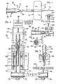
- FIG. 1 an infusion or intravenous catheter 10 including a fitting and tube- assembly 12 made in accordance with the present invention, connected to a needle assembly 13 which includes an intravenous hollow metal needle or cannula 14 having a needle hub 16 that is shown having a pair of oppositely extending, flat wings 18 integrally connected to the hub 16.
- the hub surrounds and is fixed to the needle 14.
- the hub and wings may be made of a suitable plastic such as polyvinyl chloride.
- the assembly 12 includes a fitting or connector 22 fixed to one end portion of a tube 24. The other end of tube 24 is connected to the proximal end of the needle hub 16 in fluid communication with needle 14.
- the needle 14 is inserted into the vein of a patient and the wings 17 and 18 are secured such as by taping them to the skin of a patient to maintain the needle cannula in the desired position.
- a source of infusion liquid can be connected to the fitting 22 so that infusion liquid flows through tube 24 and needle 14 to the vein of a patient.
- the fitting and tube assembly 12 is shown connected to form an intravenous catheter 10, the assembly 12 may be connected to form other apparatus such as associated with other types of catheters for purposes other than the infusion of liquid into the vein of a patient.
- the fitting 22 is shown in its original condition in Figure 2, that is, in its moulded condition before being permanently attached to the tube 24.
- the fitting 22 has a conventional luer tapered bore 26 and a pair of diametrically opposed luer lock ears or thread members 28 and 30 at the left or proximal end of the fitting.
- the tapered bore 26 and ears 28 and 30 are adapted to be connected with a conventional male luer lock connector of another device such as a luer lock connector of a tube connected to an infusion liquid source.
- fitting 22 has an annular recess or socket 32 having an annular socket wall or collar 34 at the opposite or distal end of the fitting.
- a concentric, hollow pin 36 extends axially and centrally of the socket 32 and is shown extending externally of the distal end of the socket wall 34.
- Pin 36 has a bore 38 which connects with the luer tapered bore 26.
- the proximal end portion of tube 24 is inserted into socket 32 over pin 36.
- the outer diameter of the pin 36 and the inner diameter of tube 24 are formed such that the tube forms a snug or tight friction fit with the outer surface of the pin.
- this step of inserting the tube 24 into the socket 32 of the fitting 22 is performed before the other or distal end of tube 24 is connected to the needle assembly 13 or any other device.
- Fitting 22 is a unitary member, preferably moulded of a thermoplastic material, preferably a polypropylene plastic, although other plastics such as polyethylene, polyvinyl chloride or others may be used in some cases.
- Plastic tube 24 may be made out of a suitable plastic, for example, it may be extruded from polyvinyl chloride, although it may be made of rubber or from other plastics such as polyethylene or urethane.
- the term 'plastic tube' is intended to mean a tube made of a synthetic rubber or plastic or elastomeric material.
- the fitting is inserted onto a luer tapered pin 40 of a spin-forming mechanism 42 shown for illustration in Figure 4, and which is employed in the process of permanently fixing the fitting 22 in fluid-tight, fixed connection with the tube 24.
- the mechanism pin 40 is connected to a-plate 44 which is schematically illustrated as being driven up and down on guide rails 49 by an air cylinder 46 automatically operated by a cylinder control system 48. Since the tube 24 is in snug, frictional fitting relation with the pin 36 of the fitting, the two remain together and can be handled manually or by mechanical apparatus before being permanently fixed together without the two separating.
- FIG. 4 The fitting and tube are shown in Figure 4 extending into a spin-forming die indicated generally at 50 which is mounted in fixed relation in the upper end of a driven shaft 54 mounted for rotation in bearings 56 and 58 in a stationary housing 60.
- Shaft 54 is connected to a pulley 62 which is driven by a pulley belt 64 that is, in turn, driven by a pulley 66.
- Pulley 66 is illustrated as being driven by a motor-drive system 68 through a shaft 70.
- the pulleys 62 and 66 may be mounted for rotation by pulley bearings 72 and 74, respectively, that are mounted on stationary shafts 76 and 78, respectively.
- the spin-forming die 50 has a die-forming cavity 79 with a forming surface 80 which smoothly tapers radially inwardly and downwardly to a narrow end at the bottom of the die so that the surface is generally frusto-conical in shape.
- the die cavity 79 is open at the top and bottom so that the tube 24 can pass through the die during spin-forming operations.
- Die 50 is of a metal such as a stainless steel and with the surface 80 polished.
- the fitting 22 is now moved upwardly and out of the die 50 such as by pin 40 and the action of air cylinder 46.
- the fitting 22 and the attached tube 24 are removed from pin 40 and entirely removed from the die mechanism 42 with the fitting and tube assembly in its permanently shaped condition shown in Figure 5.
- the end portion of tube 24 is tightly clamped between the inner surface of collar 34 and the outer surface of pin 36, as seen in Figure 5, so that a fluid-tight, mechanically strong connection is made between the fitting 22 and tube 24.
- the distal end of the tube 24 may then be connected to the proximal end of the needle hub 16 where the fitting and tube assembly is to be used in the infusion catheter of Figure 1.
- the fitting and tube assembly 12 can be used in relatively high fluid pressure systems without resulting in a leak at the connection between the fitting and tube or separation of that.
- Successful fitting and tube assemblies were made which employed a fitting moulded of a polypropylene plastic in the shape of fitting 22.
- the inside diameter of the collar 34 was about 3.76 millimeters (mm); the outside diameter at the distal end of the socket was about 4.52mm; the outside diameter of pin 36 was about 1.778mm; and the diameter of the pin bore 38 was about 0.965mm.
- the pin 36 had an axial length measured from the bottom of the socket of about 5.84mm and extended outwardly about 1.52mm from the free end of the socket wall 34.
- the radial dimension between the inner surface of wall 34 and the outer surface of pin 36 was about 0.991mm.
- the plastic tube was extruded from polyvinyl chloride and had inner and outer diameters of about 1.34mm and 2.18mm, respectively, so that the radial thickness of the tube side wall was about 0.42 mm .
- the finished fitting and tube assembly was tested under a pressure of 45 psi without leakage.
- the spin-forming die used to make those assemblies was similar in shape to die 50.
- the die was rotated at a speed of 2550 rpm, a force of about 108 newtons was applied to the fitting during insertion into the die, and the time of forming was about 1 second.
- specific materials for the tube and fitting, specific die speed, applied force, and forming time have been mentioned herein for purposes of illustration, it will be apparent to those skilled in the art that variations in the above can be made and good fitting and tube assemblies obtained.
- the die speed in some cases, may be a speed between 1000 and 3000 rpm.
- the force applied on the fitting during forming may be, for example, between 90 and 135 newtons.
- this method of making tube and fitting assemblies is especially important where the tubes are of relatively small size, for example, tubes having outer diameters below about 6.25mm.
- Figure 6 illustrates a method of making a tube and fitting assembly in which the fitting and tube are rotated while the die is not rotated.
- a pulley 100 driven by a pulley belt 102, rotates a pin 104 carrying a fitting 106 similar to fitting 22 in shape.
- a tube 108 having one end portion disposed on the hollow pin (not shown) of the fitting extends into an end collar 110 of the fitting.
- a forming die 112 is illustrated as being movable up and down as indicated by the arrows adjacent the die. In this case, the die moves upwardly onto the rotating collar 110 of the fitting causing the collar to be spin-formed about the upper end of tube 108 to provide a finished assembly with the tube clamped between the formed collar 110 and pin 104.
- the finished assembly in this case is similar to that shown in Figure 5 in connection with assembly 12.
Applications Claiming Priority (2)
| Application Number | Priority Date | Filing Date | Title |
|---|---|---|---|
| US533908 | 1974-12-18 | ||
| US06/533,908 US4523968A (en) | 1983-09-19 | 1983-09-19 | Tube and fitting assembly and method of making same |
Publications (3)
| Publication Number | Publication Date |
|---|---|
| EP0145139A2 true EP0145139A2 (fr) | 1985-06-19 |
| EP0145139A3 EP0145139A3 (en) | 1987-09-02 |
| EP0145139B1 EP0145139B1 (fr) | 1989-08-16 |
Family
ID=24127934
Family Applications (1)
| Application Number | Title | Priority Date | Filing Date |
|---|---|---|---|
| EP19840306261 Expired EP0145139B1 (fr) | 1983-09-19 | 1984-09-13 | Procédé de fabrication d'un assemblage de tube et raccord |
Country Status (5)
| Country | Link |
|---|---|
| US (1) | US4523968A (fr) |
| EP (1) | EP0145139B1 (fr) |
| JP (1) | JPS6090740A (fr) |
| CA (1) | CA1232504A (fr) |
| DE (1) | DE3479411D1 (fr) |
Cited By (4)
| Publication number | Priority date | Publication date | Assignee | Title |
|---|---|---|---|---|
| EP0405658A2 (fr) * | 1989-06-29 | 1991-01-02 | Cordis Europa N.V. | Procédé et dispositif pour le raccordement mutuel de tuyaux |
| BE1002911A3 (fr) * | 1987-04-23 | 1991-07-30 | Terumo Corp | Appareil pour raccorder des elements tubulaires. |
| EP0616817A1 (fr) * | 1993-03-10 | 1994-09-28 | C.R. Bard, Inc. | Cathéter avec assemblage de collecteur et méthode de sa fabrication |
| EP0786324A1 (fr) | 1996-01-24 | 1997-07-30 | B. Braun Melsungen Ag | Procédé de connexion d'un tube médicale avec un adaptateur en plastique |
Families Citing this family (11)
| Publication number | Priority date | Publication date | Assignee | Title |
|---|---|---|---|---|
| US4693710A (en) * | 1985-03-13 | 1987-09-15 | Sherwood Medical Company | Tube and fitting assembly and method of making same |
| US4806182A (en) * | 1985-10-15 | 1989-02-21 | Schneider-Shiley (U.S.A.) Inc. | Method of bonding a hub to a Teflon-lined catheter body |
| US4701291A (en) * | 1986-07-25 | 1987-10-20 | The Duriron Company, Inc. | Process of isostatic molding and bonding fluoropolymers |
| JP2519497B2 (ja) * | 1986-10-10 | 1996-07-31 | バクスター、インターナショナル、インコーポレイテッド | 物体の高周波シ―ル方法 |
| US5176662A (en) * | 1990-08-23 | 1993-01-05 | Minimed Technologies, Ltd. | Subcutaneous injection set with improved cannula mounting arrangement |
| US20060012650A1 (en) * | 2004-04-12 | 2006-01-19 | Seiko Epson Corporation | Liquid-supplying member, liquid-injection apparatus, mounting method, fluid-carrying tube, and manufacturing method of fluid-carrying tube |
| ITVI20060213A1 (it) * | 2006-07-07 | 2008-01-08 | Rinaldo Mezzalira | Assieme tubo/raccordo integrale in materiale polimerico, nonche' metodo di realizzazione dello stesso |
| US20080183103A1 (en) * | 2007-01-25 | 2008-07-31 | Cardiac Pacemakers, Inc. | Bulbous distal ended catheter |
| US9616586B1 (en) | 2015-11-11 | 2017-04-11 | Caleb Schrock | Cutting and insertion device for sap collection |
| US20190054286A1 (en) * | 2017-08-21 | 2019-02-21 | Best Medical International, Inc. | Apparatus and method for joining metal sleeve onto a tube |
| WO2020068759A1 (fr) * | 2018-09-25 | 2020-04-02 | Smiths Medical Asd, Inc. | Cloison surmoulée pour embase de cathéter |
Citations (3)
| Publication number | Priority date | Publication date | Assignee | Title |
|---|---|---|---|---|
| US2880722A (en) * | 1953-10-19 | 1959-04-07 | Becton Dickinson Co | Coupling |
| US3528869A (en) * | 1968-02-28 | 1970-09-15 | Davol Inc | Manufacture of plastic catheter |
| DE2826660A1 (de) * | 1977-06-24 | 1979-01-25 | Ligatures Peters Sa | Katheterkupplung |
Family Cites Families (12)
| Publication number | Priority date | Publication date | Assignee | Title |
|---|---|---|---|---|
| US2855929A (en) * | 1955-06-20 | 1958-10-14 | Becton Dickinson Co | Venting needle |
| US3406685A (en) * | 1963-07-23 | 1968-10-22 | Becton Dickinson Co | Catheter needle and method for its manufacture |
| US3469579A (en) * | 1967-05-05 | 1969-09-30 | Becton Dickinson Co | Catheter needle |
| US3824145A (en) * | 1969-06-20 | 1974-07-16 | Continental Plastic Ag | Apparatus for bonding a thermoplastic tubular part to the periphery of a thermoplastic tube head |
| US3690088A (en) * | 1970-09-08 | 1972-09-12 | Dave Chapman | Method of packaging |
| US3943225A (en) * | 1971-05-28 | 1976-03-09 | Promed Laboratories Inc. | Catheter |
| BE788761A (fr) * | 1971-09-14 | 1973-01-02 | Raven Carl B | Ensemble de canule d'infusion |
| US3983203A (en) * | 1973-11-16 | 1976-09-28 | Sherwood Medical Industries Inc. | Method of making a catheter with an integral Luer lock means |
| NL183053C (nl) * | 1975-10-03 | 1988-07-01 | Wavin Bv | Samengestelde kunststofbuis omvattende twee concentrische buizen, alsmede werkwijze voor het vervaardigen van een dergelijke kunststofbuis. |
| JPS5516758A (en) * | 1978-07-24 | 1980-02-05 | Hitachi Ltd | Frictional pressure welding of small-thickness pipe |
| US4354495A (en) * | 1980-10-30 | 1982-10-19 | Sherwood Medical Industries Inc. | Method of connecting plastic tube to a plastic part |
| US4405322A (en) * | 1981-12-23 | 1983-09-20 | The Kendall Company | Anesthesia device |
-
1983
- 1983-09-19 US US06/533,908 patent/US4523968A/en not_active Expired - Lifetime
-
1984
- 1984-09-04 CA CA000462367A patent/CA1232504A/fr not_active Expired
- 1984-09-10 JP JP59190449A patent/JPS6090740A/ja active Granted
- 1984-09-13 EP EP19840306261 patent/EP0145139B1/fr not_active Expired
- 1984-09-13 DE DE8484306261T patent/DE3479411D1/de not_active Expired
Patent Citations (3)
| Publication number | Priority date | Publication date | Assignee | Title |
|---|---|---|---|---|
| US2880722A (en) * | 1953-10-19 | 1959-04-07 | Becton Dickinson Co | Coupling |
| US3528869A (en) * | 1968-02-28 | 1970-09-15 | Davol Inc | Manufacture of plastic catheter |
| DE2826660A1 (de) * | 1977-06-24 | 1979-01-25 | Ligatures Peters Sa | Katheterkupplung |
Cited By (5)
| Publication number | Priority date | Publication date | Assignee | Title |
|---|---|---|---|---|
| BE1002911A3 (fr) * | 1987-04-23 | 1991-07-30 | Terumo Corp | Appareil pour raccorder des elements tubulaires. |
| EP0405658A2 (fr) * | 1989-06-29 | 1991-01-02 | Cordis Europa N.V. | Procédé et dispositif pour le raccordement mutuel de tuyaux |
| EP0405658A3 (en) * | 1989-06-29 | 1991-11-13 | Cordis Europa N.V. | Method and device for mutual connection of tubes |
| EP0616817A1 (fr) * | 1993-03-10 | 1994-09-28 | C.R. Bard, Inc. | Cathéter avec assemblage de collecteur et méthode de sa fabrication |
| EP0786324A1 (fr) | 1996-01-24 | 1997-07-30 | B. Braun Melsungen Ag | Procédé de connexion d'un tube médicale avec un adaptateur en plastique |
Also Published As
| Publication number | Publication date |
|---|---|
| JPS6090740A (ja) | 1985-05-21 |
| DE3479411D1 (en) | 1989-09-21 |
| EP0145139B1 (fr) | 1989-08-16 |
| CA1232504A (fr) | 1988-02-09 |
| JPH0374613B2 (fr) | 1991-11-27 |
| US4523968A (en) | 1985-06-18 |
| EP0145139A3 (en) | 1987-09-02 |
Similar Documents
| Publication | Publication Date | Title |
|---|---|---|
| US4693710A (en) | Tube and fitting assembly and method of making same | |
| EP0145139A2 (fr) | Procédé de fabrication d'un assemblage de tube et raccord | |
| EP0051479B1 (fr) | Procédé pour la liaison d'un tube en matière plastique avec une pièce en matière plastique | |
| US4391029A (en) | Catheter hub assembly | |
| JP4404642B2 (ja) | カテーテル及びカテーテルの製作方法 | |
| US5674201A (en) | Rotatable catheter housed within a flexible wing assembly | |
| US5366441A (en) | Catheter introducer assembly with guidewire | |
| EP1420845B2 (fr) | Procede de fabrication de catheter et catheter | |
| US6217560B1 (en) | Luer connector | |
| US5507732A (en) | Quick assembly catheter manifold | |
| EP0363953B1 (fr) | Procédé de préparation d'un cathéter | |
| US4239042A (en) | Catheter placement system | |
| CA1043970A (fr) | Methode de fabrication d'un catheter avec dispositif de verrouillage luer | |
| US3721231A (en) | Catheter for high pressure injections | |
| JPH056469B2 (fr) | ||
| IE54194B1 (en) | Medical connector | |
| US20110295208A1 (en) | Sealing Valve | |
| EP1682326B1 (fr) | Procede et moule de moulage par injection d'un catheter, catheter et son usage | |
| WO1983004214A1 (fr) | Procede et appareil de soudage par friction de materiaux thermoplastiques mous flexibles | |
| US4755649A (en) | Apparatus for compression welding of adapter and flanged catheter | |
| GB2037919A (en) | Tube & Connector Assembly | |
| CN116869630A (zh) | 一种可撕裂鞘 | |
| JPS63267134A (ja) | 管状体の接続装置 | |
| JPH0197473A (ja) | 管状部材及び管状部材組立体 | |
| JPH01256974A (ja) | 管状部材、管状部材組立体及びその製法 |
Legal Events
| Date | Code | Title | Description |
|---|---|---|---|
| PUAI | Public reference made under article 153(3) epc to a published international application that has entered the european phase |
Free format text: ORIGINAL CODE: 0009012 |
|
| AK | Designated contracting states |
Designated state(s): BE CH DE FR GB LI NL |
|
| PUAL | Search report despatched |
Free format text: ORIGINAL CODE: 0009013 |
|
| AK | Designated contracting states |
Kind code of ref document: A3 Designated state(s): BE CH DE FR GB LI NL |
|
| 17P | Request for examination filed |
Effective date: 19880222 |
|
| 17Q | First examination report despatched |
Effective date: 19880721 |
|
| GRAA | (expected) grant |
Free format text: ORIGINAL CODE: 0009210 |
|
| AK | Designated contracting states |
Kind code of ref document: B1 Designated state(s): BE CH DE FR GB LI NL |
|
| REF | Corresponds to: |
Ref document number: 3479411 Country of ref document: DE Date of ref document: 19890921 |
|
| ET | Fr: translation filed | ||
| PLBE | No opposition filed within time limit |
Free format text: ORIGINAL CODE: 0009261 |
|
| STAA | Information on the status of an ep patent application or granted ep patent |
Free format text: STATUS: NO OPPOSITION FILED WITHIN TIME LIMIT |
|
| 26N | No opposition filed | ||
| REG | Reference to a national code |
Ref country code: GB Ref legal event code: 732E |
|
| REG | Reference to a national code |
Ref country code: GB Ref legal event code: 732E |
|
| NLS | Nl: assignments of ep-patents |
Owner name: SHERWOOD SERVICES AG;TYCO GROUP S.A.R.L. |
|
| REG | Reference to a national code |
Ref country code: CH Ref legal event code: PUE Owner name: SHERWOOD MEDICAL COMPANY TRANSFER- TYCO GROUP S.A. Ref country code: CH Ref legal event code: PL |
|
| REG | Reference to a national code |
Ref country code: CH Ref legal event code: AEN Free format text: LE BREVET A ETE REACTIVE SELON LA DEMANDE DE POURSUITE DE LA PROCEDURE DU 16.05.2001. * LE BREVET A ETE REACTIVE SELON LA DEMANDE DE POURSUITE DE LA PROCEDURE DU 16.05.2001. |
|
| REG | Reference to a national code |
Ref country code: FR Ref legal event code: TP |
|
| BECA | Be: change of holder's address |
Free format text: 20010131 *SHERWOOD SERVICES A.G.:SCHWERTSTRASSE 9, 8200 SCHAFFHAUSEN |
|
| BECH | Be: change of holder |
Free format text: 20010131 *SHERWOOD SERVICES A.G.:SCHWERTSTRASSE 9, 8200 SCHAFFHAUSEN |
|
| REG | Reference to a national code |
Ref country code: GB Ref legal event code: IF02 |
|
| PGFP | Annual fee paid to national office [announced via postgrant information from national office to epo] |
Ref country code: CH Payment date: 20020821 Year of fee payment: 19 |
|
| PGFP | Annual fee paid to national office [announced via postgrant information from national office to epo] |
Ref country code: DE Payment date: 20020930 Year of fee payment: 19 |
|
| PGFP | Annual fee paid to national office [announced via postgrant information from national office to epo] |
Ref country code: NL Payment date: 20030825 Year of fee payment: 20 |
|
| PGFP | Annual fee paid to national office [announced via postgrant information from national office to epo] |
Ref country code: GB Payment date: 20030910 Year of fee payment: 20 |
|
| PGFP | Annual fee paid to national office [announced via postgrant information from national office to epo] |
Ref country code: FR Payment date: 20030918 Year of fee payment: 20 |
|
| PG25 | Lapsed in a contracting state [announced via postgrant information from national office to epo] |
Ref country code: LI Free format text: LAPSE BECAUSE OF NON-PAYMENT OF DUE FEES Effective date: 20030930 Ref country code: CH Free format text: LAPSE BECAUSE OF NON-PAYMENT OF DUE FEES Effective date: 20030930 |
|
| PGFP | Annual fee paid to national office [announced via postgrant information from national office to epo] |
Ref country code: BE Payment date: 20031016 Year of fee payment: 20 |
|
| PG25 | Lapsed in a contracting state [announced via postgrant information from national office to epo] |
Ref country code: DE Free format text: LAPSE BECAUSE OF NON-PAYMENT OF DUE FEES Effective date: 20040401 |
|
| REG | Reference to a national code |
Ref country code: CH Ref legal event code: PL |
|
| PG25 | Lapsed in a contracting state [announced via postgrant information from national office to epo] |
Ref country code: GB Free format text: LAPSE BECAUSE OF EXPIRATION OF PROTECTION Effective date: 20040912 |
|
| PG25 | Lapsed in a contracting state [announced via postgrant information from national office to epo] |
Ref country code: NL Free format text: LAPSE BECAUSE OF EXPIRATION OF PROTECTION Effective date: 20040913 |
|
| BE20 | Be: patent expired |
Owner name: *SHERWOOD SERVICES A.G. Effective date: 20040913 |
|
| REG | Reference to a national code |
Ref country code: GB Ref legal event code: PE20 |
|
| NLV7 | Nl: ceased due to reaching the maximum lifetime of a patent |
Effective date: 20040913 |