EP0144653A2 - Hanging device for coat-hangers - Google Patents
Hanging device for coat-hangers Download PDFInfo
- Publication number
- EP0144653A2 EP0144653A2 EP84112587A EP84112587A EP0144653A2 EP 0144653 A2 EP0144653 A2 EP 0144653A2 EP 84112587 A EP84112587 A EP 84112587A EP 84112587 A EP84112587 A EP 84112587A EP 0144653 A2 EP0144653 A2 EP 0144653A2
- Authority
- EP
- European Patent Office
- Prior art keywords
- hook
- fastening part
- slot
- hanging device
- hangers
- Prior art date
- Legal status (The legal status is an assumption and is not a legal conclusion. Google has not performed a legal analysis and makes no representation as to the accuracy of the status listed.)
- Withdrawn
Links
Images

Classifications
-
- A—HUMAN NECESSITIES
- A47—FURNITURE; DOMESTIC ARTICLES OR APPLIANCES; COFFEE MILLS; SPICE MILLS; SUCTION CLEANERS IN GENERAL
- A47G—HOUSEHOLD OR TABLE EQUIPMENT
- A47G25/00—Household implements used in connection with wearing apparel; Dress, hat or umbrella holders
- A47G25/14—Clothing hangers, e.g. suit hangers
- A47G25/18—Clothing hangers, e.g. suit hangers for two or more similar garments, e.g. constructed to connect to, or support, a similar hanger
- A47G25/183—Clothing hangers, e.g. suit hangers for two or more similar garments, e.g. constructed to connect to, or support, a similar hanger constructed to connect to, or support a similar hanger
- A47G25/186—Clothing hangers, e.g. suit hangers for two or more similar garments, e.g. constructed to connect to, or support, a similar hanger constructed to connect to, or support a similar hanger comprising a separate connecting member
Definitions
- the invention relates to a hanging device for hangers with the same clothes hanger hook made of wire, with which the clothes hangers and with them on the clothes hangers can be hung one behind the other with the best possible use of space and at different heights.
- Hangers are usually hung on a handrail. Due to the fact that the hangers with the clothes hanging from them are usually wider at the top than at the bottom, this known type of suspension takes up a lot of space. You cannot hang the clothes closer than the greatest thickness in the upper area, i.e. in the area of the actual hangers.
- the invention is based on this hanging device.
- the hangers hang at different heights on a handrail with the help of a triangular intermediate piece, which is hung on the one hand with hooks on the handrail and on which there are staggered buttons on one side, on which the hangers :; can be hung in a staggered height with their coat hanger hooks.
- a disadvantage of this known hanging device is that the attachment is relatively complicated and time-consuming, in particular because the intermediate piece described is first held on the horizontal holding device must attach the rod using separate hooks.
- the production of this intermediate piece together with its carrying hooks and buttons is also complex. Even more important is the fact that the available space is not optimally used there, in particular because a lower coat hanger hook with its greatest extension is located in the area of the actual coat hanger above it, which position, as explained, is relatively thick , because in addition to the coat hanger there are also the relevant items of clothing. Due to the fact that you hang the hangers on buttons that extend perpendicular to the direction of the handrail, you have to arrange the hangers with their hooks in a plane parallel to the longitudinal extension of the handrail, which also does not result in an optimal use of space.
- German patent specification 120 381 also describes a hanging device for hangers, the hangers being hung in a staggered manner in height on a horizontal support bar. This can be achieved using coat hooks of different lengths. However, this has the disadvantage that no commercially available clothes hangers or clothes hanger hooks can be used. It should be recalled that such hangers are usually made of plastic with a coat hook made of wire. Such quite simple hangers are now standardized and sold in very large numbers. It is therefore an object of the invention to design the hanging device described so that the commercially available clothes hangers described can be used.
- the invention is therefore based on the object of proposing a hanging device of the type mentioned at the beginning, in which commercially available, mutually identical clothes hanger hooks can be used, the device being designed to be simple and also structurally simple to operate. In addition, the available space should be optimally used.
- the invention is characterized in that a fastening part is provided which can be easily releasably pushed onto the lower, straight section of an upper hanger hook and which has a hook for hanging a lower hanger.
- the hanging device according to the invention is thus particularly suitable for the dispatch and storage of items of clothing suspended from hangers.
- the upper coat hanger hook is now or was previously hung on the horizontal support rod of the support system in a known manner.
- the garments are now staggered and use the space optimally.
- the clothes hangers with their items of clothing are detached from one another and from the fastening parts and then presented to the customer in a conventional manner.
- Only commercially available clothes hangers are used for the system according to the invention, only the fastening part mentioned being additionally provided. This is preferably and inexpensively as an injection molded part places and increases the price of the hanging device only insignificantly, whereby the advantage is a gain in space of about one third during transport and storage of the items of clothing.
- the slot is accessible from the rear of the fastening part facing away from the hook.
- the slot is formed by an upper holding part, which is U-shaped in a plan view, with free access from one of the sides of the fastening part, below which is spaced a lower, also U-shaped holding part, which is formed by the other side of the fastening part is freely accessible.
- the fastening part is only placed approximately horizontally, so that the straight section of the wire is between the two holding parts, and then the fastening part is rotated into the horizontal position, in which case the straight wire section is in inserts the two recordings formed by the U-profiles.
- the fastening part then sits on the upper end of the thickening of the hanger, which is formed by the actual hanger.
- the slot can also be freely accessible from one of the sides of the fastening part, the upper end of the slot then being widened towards the rear. Due to the weight of the hook or the lower hanger, the fastening part is pulled backwards into its receptacle and held there captively.
- An important embodiment is characterized in that the straight section of the coat hanger hook can be inserted into the slot via an elastically resilient constriction of the slot. This ensures that the fastening part cannot unintentionally detach from the hanger hook and is nevertheless easy to slide onto the hanger hook.
- a constriction is also formed on the hook of the fastening part.
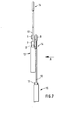
- FIGS. 1 to 3 show a one-piece injection molded part which is made of a suitable plastic material, which preferably has inherently resilient properties.
- the fastening part is essentially cuboid, a surface 1 being provided on its underside, with which the fastening part sits on the widening surface of a clothes hanger in connection with the straight part of the clothes hanger hook (cf. also FIGS. 7, 8 ).
- a slot 2 starts from one of the side surfaces of the fastening part and is guided from there essentially towards the center of the part. Following this is an angled end 3 of the slot which extends to the rear, i.e. in a direction opposite a hook 4 of the part.
- FIGS. 4 to 6 A modified embodiment of such a fastening part is shown in FIGS. 4 to 6. While in the first embodiment according to FIGS. 1 to 3 the slot 2 is accessible from the side of the part, in FIG In this second and preferred embodiment according to FIGS. 4 to 6, the fastening part is pushed from the rear onto the straight section of a clothes hanger hook, as is also shown in FIGS. 7 and 8.
- the fastening part according to FIGS. 4 to 6 has a plate-shaped body 5, on the back of which an upper holding part 6 and, spaced therefrom, a lower holding part 7 are formed.
- a hook 8 connects to the front of the body 5.
- the upper holding part 6 and the lower holding part 7 are both profiled in a U-shape, as shown in particular in FIGS. 5 and 6.
- the upper U-profile is open on one side of the fastening part and the lower U-profile only on the other side of the fastening part.
- the interiors of both U-profiles are aligned with one another and thereby form the slot 2.
- the distance between the two holding parts 6, 7 is dimensioned such that a conventional hanger hook can be inserted horizontally between the two holding parts 6, 7. It is then turned into the vertical position approximately 90 °, the straight section of the hanger hook then being inserted into the upper and lower slots 2 of the two holding parts 6, 7.
- a narrow point 9 is also formed on both holding parts, as a result of which the clothes hanger hook is held captively in slot 2. If the fastening part is to be detached from the clothes hanger hook, the movement described must be carried out in the reverse order, the wire of the clothes hanger hook sliding over the constriction 9 and then being released.
- a constriction 10 is also formed on the hook 8.
- the hook 8 forms together with his Body 5 from an insertion space 11 for the bent portion of a lower hanger hook, as shown in Figures 7 and 8.
- an upper, conventional clothes hanger 12 is hung in the usual way on a horizontal clothes rail (cf. FIGS. 7, 8).
- the described fastening part according to FIGS. 1 to 3 or 4 to 6 is put on the lower straight section 13 of the clothes hanger hook 14, thus inserting the injection molded part with its slot 2 into the section 13 of the clothes hanger hook.
- this bears against the rearward bent end of the slot 2 and is held there in a positionally secure manner via the bend.
- At the entrance to the slot there may also be a constriction 9, so that the injection molded part must be inserted into the slot in a snap fit.
- section 13 is also seated in slot 2.
- a plastic part according to the invention can in turn be plugged onto this second coat hanger, and so on, until the existing room height with the staggered, tiered clothes is used. You can then start again with an upper coat hook, as described above, until the specified length of the clothes rail is also used.
- FIGS. 7 and 8 also show that, for the best possible use of space, the lower hanger 15 ends with its hook 14, which usually has a thickened end, at a short distance above the actual plastic part 16 of the upper hanger 12.
- the thickness of the fastening part is not greater than the thickness of this plastic part 16 plus the thickness of the wire thickness of the hanger hook.
- the back of the fastening part does not protrude beyond the back of the plastic part 16, as can be seen in particular from FIG. At the front, the fastening part protrudes only slightly beyond the wire thickness of the lower hanger hook.
- the fastening part sits on a cylindrical extension 17, also made of plastic, of the hanger, which extension serves to receive and anchor the hanger hook if the hanger has such an extension.
Abstract
Description
Die Erfindung betrifft eine Hängevorrichtung für Kleiderbügel mit einander gleichen Kleiderbügelhaken aus Draht, mit der die Kleiderbügel und mit ihnen an den Kleiderbügeln aufgehängte Bekleidungsstücke unter möglichst guter Raumausnutzung hintereinander und in unterschiedlicher Höhe aufgehängt werden können.The invention relates to a hanging device for hangers with the same clothes hanger hook made of wire, with which the clothes hangers and with them on the clothes hangers can be hung one behind the other with the best possible use of space and at different heights.
Üblicherweise werden Kleiderbügel an einer Haltestange aufgehängt. Bedingt durch den Umstand, daß die Kleiderbügel mit den an ihnen aufgehängten Bekleidungsstücken oben üblicherweise breiter sind als unten, wird bei dieser bekannten Aufhängungsart relativ viel Platz verschenkt. Man kann die Kleider nämlich nicht enger hängen als dies die größte Dicke im oberen Bereich, d.h. im Bereich der eigentlichen Kleiderbügel, zuläßt.Hangers are usually hung on a handrail. Due to the fact that the hangers with the clothes hanging from them are usually wider at the top than at the bottom, this known type of suspension takes up a lot of space. You cannot hang the clothes closer than the greatest thickness in the upper area, i.e. in the area of the actual hangers.
Hier hat bereits ein System Abhilfe geschaffen, welches in der Deutschen Patentschrift 255 037 beschrieben ist. Von dieser Hängevorrichtung geht die Erfindung aus. Dort hängen die Kleiderbügel in unterschiedlicher Höhe an einer Haltestange mit Hilfe eines dreieckförmigen Zwischenstücks, welches einerseits mit Haken an der Haltestange aufgehängt ist und an dem sich an der einen Seite gestaffelt Knöpfe befinden, an denen die Kleiderbügel:; mit ihren Kleiderbügelhaken in der Höhe gestaffelt aufgehängt werden können.A system has already remedied this, which is described in German patent specification 255 037. The invention is based on this hanging device. There the hangers hang at different heights on a handrail with the help of a triangular intermediate piece, which is hung on the one hand with hooks on the handrail and on which there are staggered buttons on one side, on which the hangers :; can be hung in a staggered height with their coat hanger hooks.
Nachteilig bei dieser bekannten Hängevorrichtung ist es aber, daß die Anbringung verhältnismäßig kompliziert und zeitaufwendig ist, insbesondere, weil man zunächst das beschriebene Zwischenstück an die waagrechte Haltestange über gesonderte Haken befestigen muß. Auch ist die Herstellung dieses Zwischenstücks mitsamt seinen Traghaken und Knöpfen aufwendig. Noch stärker fällt ins Gewicht, daß dort der zur Verfügung stehende Raum doch nicht optimal ausgenutzt wird, insbesondere, weil ein unterer Kleiderbügelhaken mit seiner größten Ausdehnung sich im Bereich des jeweils über ihm befindlichen eigentlichen Kleiderbügels befindet, welche Stelle, wie erläutert, verhältnismäßig dick ist, weil dort ja zusätzlich zum Kleiderbügel auch noch die betreffenden Kleidungsstücke sich befinden. Dadurch bedingt, daß man die Kleiderbügel an Knöpfen aufhängt, die sich senkrecht zur Richtung der_Haltestange erstrecken, muß man dort die Kleiderbügel mit ihren Haken in einer Ebene parallel zur Längserstreckung der Haltestange anordnen, was ebenfalls keine optimale Raumausnutzung ergibt.A disadvantage of this known hanging device, however, is that the attachment is relatively complicated and time-consuming, in particular because the intermediate piece described is first held on the horizontal holding device must attach the rod using separate hooks. The production of this intermediate piece together with its carrying hooks and buttons is also complex. Even more important is the fact that the available space is not optimally used there, in particular because a lower coat hanger hook with its greatest extension is located in the area of the actual coat hanger above it, which position, as explained, is relatively thick , because in addition to the coat hanger there are also the relevant items of clothing. Due to the fact that you hang the hangers on buttons that extend perpendicular to the direction of the handrail, you have to arrange the hangers with their hooks in a plane parallel to the longitudinal extension of the handrail, which also does not result in an optimal use of space.
Die Deutsche Patentschrift 120 381 beschreibt ebenfalls eine Hängevorrichtung für Kleiderbügel, wobei die Kleiderbügel in der Höhe gestaffelt an einer waagrechten Haltestange aufgehängt werden. Dies erreicht man dort über unterschiedlich lange Kleiderbügelhaken. Damit ist aber der Nachteil verbunden, daß keine handelsüblichen Kleiderbügel bzw. Kleiderbügelhaken verwendet werden können. Hier sei in Erinnerung gerufen, daß derartigew-Kleiderbügel in der Regel aus Kunststoff bestehen mit einem Kleiderbügelhaken aus Draht. Solche recht einfachen Kleiderbügel werden heute in sehr großen Stückzahlen genormt hergestellt und vertrieben. Es ist daher ein Ziel der Erfindung, die beschriebene Hängevorrichtung so auszugestalten, daß die beschriebenen, handelsüblichen Kleiderbügel dabei eingesetzt werden können.German patent specification 120 381 also describes a hanging device for hangers, the hangers being hung in a staggered manner in height on a horizontal support bar. This can be achieved using coat hooks of different lengths. However, this has the disadvantage that no commercially available clothes hangers or clothes hanger hooks can be used. It should be recalled that such hangers are usually made of plastic with a coat hook made of wire. Such quite simple hangers are now standardized and sold in very large numbers. It is therefore an object of the invention to design the hanging device described so that the commercially available clothes hangers described can be used.
Der Erfindung liegt somit die Aufgabe zugrunde, eine Hängevorrichtung der eingangs genannten Art vorzuschlagen, bei der handelsübliche, einander gleiche Kleiderbügelhaken verwendet werden können, wobei die Vorrichtung in der Bedienung einfach und auch konstruktiv einfach aufgebaut sein soll. Außerdem soll der zur Verfügung stehende Raum optimal ausgenutzt werden.The invention is therefore based on the object of proposing a hanging device of the type mentioned at the beginning, in which commercially available, mutually identical clothes hanger hooks can be used, the device being designed to be simple and also structurally simple to operate. In addition, the available space should be optimally used.
Zur Lösung dieser Aufgabe ist die Erfindung dadurch gekennzeichnet, daß ein Befestigungsteil vorgesehen ist, welches leicht lösbar auf den unteren, geraden Abschnitt eines oberen Kleiderbügelhakens aufschiebbar ist und das einen Haken zum Aufhängen eines unteren Kleiderbügels hat.To achieve this object, the invention is characterized in that a fastening part is provided which can be easily releasably pushed onto the lower, straight section of an upper hanger hook and which has a hook for hanging a lower hanger.
Die erfindungsgemäße Hängevorrichtung ist somit insbesondere für den Versand und die Lagerung von an Kleiderbügeln aufgehängten Bekleidungsstücken geeignet. Man befestigt mit einem Handgriff das Befestigungsteil am unteren Abschnitt des jeweils oberen Kleiderbügelhakens und hängt auf den Haken des Befestigungsteils einen unteren Kleiderbügelhaken und so fort. Der jeweils obere Kleiderbügelhaken wird jetzt oder wurde vorher auf die waagrechte Haltestange des Haltesystems in bekannter Weise aufgehängt. Die Bekleidungsstücke hängen jetzt gestaffelt und unter optimaler Raumausnutzung. Am Ort der Verwendung, beispielsweise in einem Ladengeschäft, werden die Kleiderbügel mit ihren Bekleidungsstücken voneinander und von den Befestigungsteilen gelöst und dann in herkömmlicher Art und Weise dem Kunden dargeboten. Für das erfindungsgemäße System werden nur handelsübliche Kleiderbügel verwendet, wobei lediglich zusätzlich das erwähnte Befestigungsteil vorzusehen ist. Dieses wird vorzugsweise und preisgünstig als Spritzgußteil hergestellt und verteuert die Hängevorrichtung nur unwesentlich, wobei als Vorteil ein Platzgewinn von etwa einem Drittel beim Transport und bei der Lagerung der Kleidungsstücke entsteht.The hanging device according to the invention is thus particularly suitable for the dispatch and storage of items of clothing suspended from hangers. One fastens the fastening part to the lower section of the upper hanger hook and hangs a lower hanger hook on the hook of the fastening part and so on. The upper coat hanger hook is now or was previously hung on the horizontal support rod of the support system in a known manner. The garments are now staggered and use the space optimally. At the place of use, for example in a retail store, the clothes hangers with their items of clothing are detached from one another and from the fastening parts and then presented to the customer in a conventional manner. Only commercially available clothes hangers are used for the system according to the invention, only the fastening part mentioned being additionally provided. This is preferably and inexpensively as an injection molded part places and increases the price of the hanging device only insignificantly, whereby the advantage is a gain in space of about one third during transport and storage of the items of clothing.
Bevorzugt wird es, wenn am Befestigungsteil ein Schlitz zum Aufschieben auf den geraden Abschnitt des oberen Kleiderbügelhakens ausgebildet ist. Dies sichert eine leichte Bedienbarkeit, verbunden mit besonders kostengünstiger Herstellung.It is preferred if a slot is formed on the fastening part for sliding onto the straight section of the upper hanger hook. This ensures ease of use combined with particularly inexpensive manufacture.
Fernerhin wird es bevorzugt, wenn der Schlitz von der dem Haken abgewandten Rückseite des Befestigungsteils her zugänglich ist. Bei dieser Ausbildung wird das Anbringen und Abnehmen des Befestigungsteils besonders einfach.Furthermore, it is preferred if the slot is accessible from the rear of the fastening part facing away from the hook. With this design, attaching and detaching the fastener is particularly easy.
Diesbezüglich wird es bevorzugt, wenn der Schlitz durch ein oberes, in einer Draufsicht U-förmig profiliertes Halteteil mit freiem Zugang von einer der Seiten des Befestigungsteils gebildet wird, unter dem sich davon beabstandet ein unteres, ebenfalls U-förmig profiliertes Halteteil befindet, das von der anderen Seite des Befestigungsteils her frei zugänglich ist. Zum Einhaken dieses Befestigungsteils in den geraden Abschnitt des Drahtbügels wird das Befestigungsteil lediglich etwa waagrecht gestellt, so daß der gerade Abschnitt des Drahtes sich zwischen den beiden Halteteilen befindet,und dann wird das Befestigungsteil in die waagrechte Lage gedreht, wobei dann sich der gerade Drahtabschnitt in die beiden durch die U-Profile gebildeten Aufnahmen einlegt. Das Befestigungsteil sitzt dann auf dem oberen Ende der Verdickung des Kleiderbügels auf, die durch den eigentlichen Kleiderbügel gebildet wird.In this regard, it is preferred if the slot is formed by an upper holding part, which is U-shaped in a plan view, with free access from one of the sides of the fastening part, below which is spaced a lower, also U-shaped holding part, which is formed by the other side of the fastening part is freely accessible. To hook this fastening part into the straight section of the wire bracket, the fastening part is only placed approximately horizontally, so that the straight section of the wire is between the two holding parts, and then the fastening part is rotated into the horizontal position, in which case the straight wire section is in inserts the two recordings formed by the U-profiles. The fastening part then sits on the upper end of the thickening of the hanger, which is formed by the actual hanger.
Der Schlitz kann auch von einer der Seiten des Befestigungsteils her frei zugänglich sein, wobei dann das obere Ende des Schlitzes nach hinten erweitert ist. Durch das Gewicht des Hakens bzw. des unteren Kleiderbügels wird hierbei das Befestigungsteil nach rückwärts in seine Aufnahme gezogen und dort unverlierbar gehalten.The slot can also be freely accessible from one of the sides of the fastening part, the upper end of the slot then being widened towards the rear. Due to the weight of the hook or the lower hanger, the fastening part is pulled backwards into its receptacle and held there captively.
Eine wichtige Ausgestaltung ist dadurch gekennzeichnet, daß der gerade Abschnitt des Kleiderbügelhakens über eine elastisch federnde Engstelle des Schlitzes in den Schlitz einschiebbar ist. Dadurch wird sichergestellt, daß der Befestigungsteil nicht ungewollt sich vom Kleiderbügelhaken lösen kann und dennoch leicht auf den Kleiderbügelhaken aufschiebbar ist.An important embodiment is characterized in that the straight section of the coat hanger hook can be inserted into the slot via an elastically resilient constriction of the slot. This ensures that the fastening part cannot unintentionally detach from the hanger hook and is nevertheless easy to slide onto the hanger hook.
Aus denselben Gründen wird es bevorzugt, wenn auch am Haken des Befestigungsteils eine Engstelle ausgebildet ist.For the same reasons, it is preferred if a constriction is also formed on the hook of the fastening part.
Die Erfindung wird im folgenden anhand von Ausführungsbeispielen näher erläutert, aus denen sich weitere wichtige Merkmale ergeben. Es zeigt:
- Figur 1 eine erste Ausführungsform eines erfindungsgemäßen Befestigungsteils in einer Seitenansicht;
Figur 2 eine Ansicht in Richtung des Pfeiles A von Figur 1;Figur 3 eine Ansicht in Richtung des Pfeiles B von Figur 1;Figur 4 eine Seitenansicht einer zweiten Ausführungsform des erfindungsgemäßen Befestigungsteils;Figur 5 eine Ansicht in Richtung des Pfeiles A vonFigur 4;Figur 6 eine Ansicht in Richtung des Pfeiles B vonFigur 4;Figur 7 schematisch und in einer Seitenansicht zwei Kleiderbügel, von denen der untere mit Hilfe eines erfindungsgemäßen Befestigungsteils nach Figur 4 - 6 am oberen Kleiderbügel aufgehängt ist;Figur 8 eine Ansicht vonFigur 7 in Richtung des Pfeiles A.
- Figure 1 shows a first embodiment of a fastening part according to the invention in a side view;
- Figure 2 is a view in the direction of arrow A of Figure 1;
- Figure 3 is a view in the direction of arrow B of Figure 1;
- FIG. 4 shows a side view of a second embodiment of the fastening part according to the invention;
- Figure 5 is a view in the direction of arrow A of Figure 4;
- Figure 6 is a view in the direction of arrow B of Figure 4;
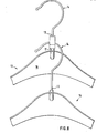
- FIG. 7 schematically and in a side view two clothes hangers, the lower of which is suspended from the upper clothes hanger with the aid of a fastening part according to FIGS. 4-6;
- Figure 8 is a view of Figure 7 in the direction of arrow A.
Zunächst sei die erste Ausführungsform des erfindungsgemäßen Befestigungsteils anhand der Figuren 1 bis 3 erläutert. Diese Figuren zeigen ein einstückiges Spritzgußteil, das aus einem geeigneten Kunststoffmaterial hergestellt ist, welches vorzugsweise in sich elastisch federnde Eigenschaften hat. Das Befestigungsteil ist im wesentlichen quaderförmig ausgebildet, wobei an seiner Unterseite eine Fläche 1 vorgesehen ist, mit dem das Befestigungsteil im Gebrauch auf der sich verbreiternden Fläche eines Kleiderbügels im Anschluß an den geraden Teil des Kleiderbügelhakens aufsitzt (vgl. hierzu auch Fig. 7, 8).First of all, the first embodiment of the fastening part according to the invention will be explained with reference to FIGS. 1 to 3. These figures show a one-piece injection molded part which is made of a suitable plastic material, which preferably has inherently resilient properties. The fastening part is essentially cuboid, a surface 1 being provided on its underside, with which the fastening part sits on the widening surface of a clothes hanger in connection with the straight part of the clothes hanger hook (cf. also FIGS. 7, 8 ).
Ein Schlitz 2 geht von einer der Seitenflächen des Befestigungsteils aus und ist von dort im wesentlichen in Richtung zur Mitte des Teils geführt. Daran anschließend ist ein abgewinkeltes Ende 3 des Schlitzes vorgesehen, der sich nach hinten erstreckt, d.h. in eine Richtung, die einem Haken 4 des Teils entgegengesetzt ist.A
Eine abgeänderte Ausführungsform eines derartigen Befestigungsteils zeigen die Figuren 4 bis 6. Während bei der ersten Ausführungsform nach Figur" 1 bis 3 der Schlitz 2 von der Seite des Teils her zugänglich ist, wird bei dieser zweiten und bevorzugten Ausführungsform nach Figur 4 bis 6 das Befestigungsteil von der Rückseite her auf den geraden Abschnitt eines Kleiderbügelhakens aufgeschoben, wie dies auch in den Figuren 7 und 8 gezeigt ist. Hierzu besitzt-das Befestigungsteil nach Fig. 4 bis 6 einen plattenförmigen Körper 5, an dessen Rückseite oben ein oberes Halteteil 6 und, davon beabstandet, ein unteres Halteteil 7 angeformt ist. An die Vorderseite des Körpers 5 schließt sich ein Haken 8 an.A modified embodiment of such a fastening part is shown in FIGS. 4 to 6. While in the first embodiment according to FIGS. 1 to 3 the
Das obere Halteteil 6 und das untere Halteteil 7 sind beide U-förmig profiliert, wie insbesondere die Figuren 5 und 6 zeigen. Das obere U-Profil ist zur einen Seite des Befestigungsteils geöffnet und das untere U-Profil nur anderen Seite des Befestigungsteils. Die Innenräume beider U-Profile fluchten miteinander und bilden dadurch den Schlitz 2 aus. Der Abstand zwischen den beiden Halteteilen 6, 7 ist so bemessen, daß ein herkömmlicher Kleiderbügelhaken zwischen die beiden Halteteile 6, 7 waagrecht eingeführt werden kann. Er wird dann in die senkrechte Lage etwa um 90° gedreht, wobei sich dann der gerade Abschnitt des Kleiderbügelhakens in den oberen und den unteren Schlitz 2 der beiden Halteteile 6, 7 einlegt.The
An beiden Halteteilen ist noch eine Engstelle 9 ausgebildet, wodurch der Kleiderbügelhaken im Schlitz 2 unverlierbar gehalten wird. Soll das Befestigungsteil vom Kleiderbügelhaken gelöst werden, so muß die beschriebene Bewegung in umgekehrter Reihenfolge durchgeführt werden, wobei der Draht des Kleiderbügelhakens über die Engstelle 9 gleitet und dann freikommt.A
In ähnlicher Weise ist auch eine Engstelle 10 am Haken 8 ausgebildet. Der Haken 8 bildet zusammen mit seinem Körper 5 einen Einsteckraum 11 für den gebogenen Abschnitt eines unteren Kleiderbügelhakens aus, wie dies die Figuren 7 und 8 zeigen.In a similar way, a
Um Kleider unter möglichst guter Raumausnutzung aufzuhängen, beispielsweise in einem Container, Lager oder dergleichen, wird ein oberer, herkömmlicher Kleiderbügel 12 in üblicher Weise auf eine waagrechte Kleiderstange aufgehängt (vgl. Fig. 7, 8). Das beschriebene Befestigungsteil nach Fig. 1 bis 3 oder Fig. 4 bis 6, wird auf den unteren geraden Abschnitt 13 des Kleiderbügelhakens 14 aufgesteckt, wobei man also das Spritzgußteil mit seinem Schlitz 2 in den Abschnitt 13 des Kleiderbügelhakens einführt. Dieser legt sich bei der Ausführungsform nach Fig. 1 bis 3 an das nach hinten abgebogene Ende des Schlitzes 2 an und wird dort lagesicher über die Abbiegung gehalten. Am Eingang des Schlitzes kann auch noch ::ei.ne Engstelle 9 vorgesehen sein, so daß das Spritzgußteil gewissermaßen in einem Schnappsitz in den Schlitz eingeführt werden muß. Bei der Ausführungsform nach Fig. 4 bis 6 sitzt der Abschnitt 13 ebenfalls im Schlitz 2.In order to hang up clothes with the best possible use of space, for example in a container, warehouse or the like, an upper,
Jetzt kann ein zweiter, gleich ausgebildeter unterer Kleiderbügel 15 auf den Haken 4 bzw. 8 des Kunststoffteiles aufgehängt werden.Now a second, equally designed
Auf diesen zweiten Kleiderbügel aknn wiederum ein erfindungsgemäßes Kunststoffteil aufgesteckt werden, und so fort, bis die vorhandene Raumhöhe mit den stufig gestaffelt gehängten Kleidungsstücken ausgenutzt ist. Man kann dann wieder mit einem oberen Kleiderbügelhaken, wie vorstehend beschrieben, beginnen, bis auch die vorgegebene Länge der Kleiderstange ausgenutzt ist.A plastic part according to the invention can in turn be plugged onto this second coat hanger, and so on, until the existing room height with the staggered, tiered clothes is used. You can then start again with an upper coat hook, as described above, until the specified length of the clothes rail is also used.
Die Figuren 7 und 8 lassen auch erkennen, daß zwecks möglichst guter Raumausnutzung der untere Kleiderbügel 15 mit seinem Haken 14, der üblicherweise ein verdicktes Ende hat, in einem kurzen Abstand über dem eigentlichen Kunststoffteil 16 des oberen Kleiderbügels 12 endet. Die Dicke des Befestigungsteils ist nicht größer als die Dicke dieses Kunststoffteils 16 zuzüglich der Dicke der Drahtstärke des Kleiderbügelhakens. Die Rückseite des Befestigungsteils ragt nicht über die Rückseite des Kunststoffteils 16 hinaus, wie sich insbesondere aus Figur 7 ergibt. An der Vorderseite ragt das Befestigungsteil nur unwesentlich über die Drahtstärke des unteren Kleiderbügelhakens hinaus. Das Befestigungsteil sitzt auf einem zylindrischen Fortsatz 17, ebenfalls aus Kunststoff, des Kleiderbügels auf, welcher Fortsatz zur Aufnahme und Verankerung des Kleiderbügelhakens dient, falls der Kleiderbügel einen solchen Fortsatz hat.FIGS. 7 and 8 also show that, for the best possible use of space, the
Claims (7)
daß ein Befestigungsteil vorgesehen ist, welches leicht lösbar auf den unteren geraden Abschnitt (13) eines oberen Kleiderbügelhakens (14) aufschiebbar ist und das einen Haken (4; 8) zum Aufhängen eines unteren Kleiderbügels (15) hat.1.Hanging device for hangers (12, 15) with identical clothes hooks (14) made of wire with which the clothes hangers (12, 15) and with them on the hangers (12, 15) hang items of clothing one behind the other and at different heights, making the best possible use of space can be hung, characterized in that
that a fastening part is provided, which can be easily detachably pushed onto the lower straight section (13) of an upper hanger hook (14) and which has a hook (4; 8) for hanging a lower hanger (15).
dadurch gekennzeichnet ,
daß am Befestigungsteil ein Schlitz (2) zum Aufschieben auf den geraden Abschnitt (13) des oberen Kleiderbügelhakens (14) ausgebildet ist.2. Hanging device according to claim 1,
characterized ,
that a slot (2) for sliding onto the straight section (13) of the upper hanger hook (14) is formed on the fastening part.
daß der Schlitz (2) von der dem Haken (8) abgewandten Rückseite des Befestigungsteils her zugänglich ist.3. Hanging device according to claim 2, characterized in that
that the slot (2) is accessible from the rear of the fastening part facing away from the hook (8).
daß der Schlitz (2) durch ein oberes, in einer Draufsicht U-förmig profiliertes Halteteil (6) mit freiem Zugang von einer der Seiten des Befestigungsteils gebildet wird, unter dem sich davon beabstandet ein unteres, ebenfalls U-förmig profiliertes Halteteil (7) befindet, das von der anderen Seite des Befestigungs-teils her frei zugänglich ist.4. Hanging device according to claim 3, characterized in
that the slot (2) is formed by an upper holding part (6) which is U-shaped in plan view and has free access from one of the sides of the fastening part, under which a lower holding part (7) which is also U-shaped is spaced apart is, the s-partly ago freely accessible from the other side of FIXING g.
daß der Schlitz (2) von einer der Seiten des Befestigungsteils her frei zugänglich ist, wobei das obere Ende (3) des Schlitzes (2) nach hinten erweitert ist.5. Hanging device according to claim 2, characterized in
that the slot (2) is freely accessible from one of the sides of the fastening part, the upper end (3) of the slot (2) being widened towards the rear.
Applications Claiming Priority (2)
| Application Number | Priority Date | Filing Date | Title |
|---|---|---|---|
| DE19838334310 DE8334310U1 (en) | 1983-11-30 | 1983-11-30 | HANGER FOR HANGER |
| DE8334310U | 1983-11-30 |
Publications (2)
| Publication Number | Publication Date |
|---|---|
| EP0144653A2 true EP0144653A2 (en) | 1985-06-19 |
| EP0144653A3 EP0144653A3 (en) | 1986-02-05 |
Family
ID=6759366
Family Applications (1)
| Application Number | Title | Priority Date | Filing Date |
|---|---|---|---|
| EP84112587A Withdrawn EP0144653A3 (en) | 1983-11-30 | 1984-10-18 | Hanging device for coat-hangers |
Country Status (2)
| Country | Link |
|---|---|
| EP (1) | EP0144653A3 (en) |
| DE (1) | DE8334310U1 (en) |
Cited By (6)
| Publication number | Priority date | Publication date | Assignee | Title |
|---|---|---|---|---|
| US4653678A (en) * | 1985-10-04 | 1987-03-31 | Batts, Inc. | Ganging hook for garment hangers |
| US5074445A (en) * | 1990-08-29 | 1991-12-24 | Chen Chia Sing | Garment hanger with swivel hook and ganging hook |
| GR900100215A (en) * | 1990-03-22 | 1992-06-30 | Mariettos Anastasios I | Method and means for the achievement of a sequence of connected hangers |
| GB2383746A (en) * | 2001-12-21 | 2003-07-09 | Stewart Melville Colborne | A device for hanging garments on a chair |
| US6595354B1 (en) * | 2002-04-03 | 2003-07-22 | Tumi, Inc. | Luggage with low-profile hanger bracket |
| US7228962B2 (en) | 2004-12-15 | 2007-06-12 | Tumi, Inc. | Luggage with low-profile hanger bracket and harness |
Citations (3)
| Publication number | Priority date | Publication date | Assignee | Title |
|---|---|---|---|---|
| US2498400A (en) * | 1948-02-07 | 1950-02-21 | Lude Miriam A Du | Support for garment hangers |
| GB739207A (en) * | 1953-07-02 | 1955-10-26 | Twinco Ltd | Improvements in hangers or airers for lightweight garments |
| FR2276022A1 (en) * | 1974-06-28 | 1976-01-23 | Hazenveld Ind Handelmaatschapp | Hook attachments for clothes hanger - has stiffening bends to top curved hook and around cross beam |
-
1983
- 1983-11-30 DE DE19838334310 patent/DE8334310U1/en not_active Expired
-
1984
- 1984-10-18 EP EP84112587A patent/EP0144653A3/en not_active Withdrawn
Patent Citations (3)
| Publication number | Priority date | Publication date | Assignee | Title |
|---|---|---|---|---|
| US2498400A (en) * | 1948-02-07 | 1950-02-21 | Lude Miriam A Du | Support for garment hangers |
| GB739207A (en) * | 1953-07-02 | 1955-10-26 | Twinco Ltd | Improvements in hangers or airers for lightweight garments |
| FR2276022A1 (en) * | 1974-06-28 | 1976-01-23 | Hazenveld Ind Handelmaatschapp | Hook attachments for clothes hanger - has stiffening bends to top curved hook and around cross beam |
Cited By (6)
| Publication number | Priority date | Publication date | Assignee | Title |
|---|---|---|---|---|
| US4653678A (en) * | 1985-10-04 | 1987-03-31 | Batts, Inc. | Ganging hook for garment hangers |
| GR900100215A (en) * | 1990-03-22 | 1992-06-30 | Mariettos Anastasios I | Method and means for the achievement of a sequence of connected hangers |
| US5074445A (en) * | 1990-08-29 | 1991-12-24 | Chen Chia Sing | Garment hanger with swivel hook and ganging hook |
| GB2383746A (en) * | 2001-12-21 | 2003-07-09 | Stewart Melville Colborne | A device for hanging garments on a chair |
| US6595354B1 (en) * | 2002-04-03 | 2003-07-22 | Tumi, Inc. | Luggage with low-profile hanger bracket |
| US7228962B2 (en) | 2004-12-15 | 2007-06-12 | Tumi, Inc. | Luggage with low-profile hanger bracket and harness |
Also Published As
| Publication number | Publication date |
|---|---|
| EP0144653A3 (en) | 1986-02-05 |
| DE8334310U1 (en) | 1984-03-01 |
Similar Documents
| Publication | Publication Date | Title |
|---|---|---|
| DE60003891T2 (en) | FASTENING DEVICE WITH A BAR SUSPENDED FROM A WALL | |
| DE3326908C2 (en) | Sales stand with a perforated plate and a carrier plate detachably connected to the perforated plate | |
| DE2216777C3 (en) | Clamping strip for hanging up sheet-like or sheet-like pieces of material | |
| DE3410974A1 (en) | CEILING FASTENING FOR DECORATION ELEMENTS AND THE LIKE | |
| EP0362968A1 (en) | Display wall | |
| DE3214727A1 (en) | CONNECTING DEVICE | |
| DE2446804A1 (en) | DRAWER | |
| DE60112105T2 (en) | SUSPENSION | |
| EP0144653A2 (en) | Hanging device for coat-hangers | |
| DE2648467A1 (en) | Bolt fixture for motor vehicle bumper - has U-form clamp strip retained in bumper plate aperture by sprung integral arms | |
| DE2003366C3 (en) | Curtain hanger | |
| EP0098455A1 (en) | Bracket standard for a partition panel or a wall covering | |
| DE2948353C2 (en) | Device for holding objects | |
| DE19600175C1 (en) | Holding system for kitchen utensils | |
| EP0088070B1 (en) | Clamp | |
| DE2041642B2 (en) | Suspended ceiling with ceiling elements attached to carrier rails using mounting brackets | |
| DE3348508C2 (en) | Plastics clothes hanger with integral clamps | |
| DE3700435A1 (en) | Insertable divider for subdividing compartments of drawers and the like, in particular for chemist's shop cabinets | |
| EP0427914A1 (en) | Shelf | |
| DE3905413A1 (en) | Detachable mounting for a rest or the like | |
| EP0587040B1 (en) | Shelf | |
| DE8405471U1 (en) | Perforated plate hook | |
| DE3916440C1 (en) | Tool holding wall with several, vertical inserting bars - which have aperture raster corresp. to profile strip cross=section | |
| DE2840880A1 (en) | Clothes hanger stand for public places - has hanging section, support bar and hanger with slide piece and guide | |
| DD255074A1 (en) | TIPPING DEVICE FOR MAGAZINE HARVEST |
Legal Events
| Date | Code | Title | Description |
|---|---|---|---|
| PUAI | Public reference made under article 153(3) epc to a published international application that has entered the european phase |
Free format text: ORIGINAL CODE: 0009012 |
|
| AK | Designated contracting states |
Designated state(s): AT BE CH DE FR GB IT LI NL SE |
|
| PUAL | Search report despatched |
Free format text: ORIGINAL CODE: 0009013 |
|
| AK | Designated contracting states |
Designated state(s): AT BE CH DE FR GB IT LI NL SE |
|
| STAA | Information on the status of an ep patent application or granted ep patent |
Free format text: STATUS: THE APPLICATION IS DEEMED TO BE WITHDRAWN |
|
| 18D | Application deemed to be withdrawn |
Effective date: 19861006 |
|
| RIN1 | Information on inventor provided before grant (corrected) |
Inventor name: KOTOWSKI, KLEMENS P. |