EP0144591A2 - Adjustable switching device - Google Patents
Adjustable switching device Download PDFInfo
- Publication number
- EP0144591A2 EP0144591A2 EP84111682A EP84111682A EP0144591A2 EP 0144591 A2 EP0144591 A2 EP 0144591A2 EP 84111682 A EP84111682 A EP 84111682A EP 84111682 A EP84111682 A EP 84111682A EP 0144591 A2 EP0144591 A2 EP 0144591A2
- Authority
- EP
- European Patent Office
- Prior art keywords
- button
- switch
- stop edge
- switch according
- spring
- Prior art date
- Legal status (The legal status is an assumption and is not a legal conclusion. Google has not performed a legal analysis and makes no representation as to the accuracy of the status listed.)
- Withdrawn
Links
Images


Classifications
-
- H—ELECTRICITY
- H01—ELECTRIC ELEMENTS
- H01H—ELECTRIC SWITCHES; RELAYS; SELECTORS; EMERGENCY PROTECTIVE DEVICES
- H01H9/00—Details of switching devices, not covered by groups H01H1/00 - H01H7/00
- H01H9/02—Bases, casings, or covers
- H01H9/06—Casing of switch constituted by a handle serving a purpose other than the actuation of the switch, e.g. by the handle of a vacuum cleaner
- H01H9/061—Casing of switch constituted by a handle serving a purpose other than the actuation of the switch, e.g. by the handle of a vacuum cleaner enclosing a continuously variable impedance
Definitions
- the invention relates to a switch with a button that can be displaced in the longitudinal direction against the force of a spring in a switch housing, at the start of which an electrical switching bridge switches and which adjusts a variable resistance depending on the stroke of the displacement distance.
- Such switches are used in electrical hand machine tools, in particular hand drills.
- the switching bridge of DE-OS 28 38 934 is complex. Because in addition to the spring resetting the button, it needs its own tension spring. In addition, their mating contact must be connected to the relevant terminal via an electrical connection.
- a disadvantage of the switch according to DE-OS 28 38 934 is also that there is no possibility for the user to preset the resistance value and thus the speed at a drilling machine, which is to be achieved at the maximum when a key is pressed.
- the user desires such a presetting, for example when he is working on a material on which a certain working speed of the machine should not be exceeded.
- EP-FS 00 11 440 describes a switch in which a rotary knob is arranged on the key, by means of which it can be determined how far the key should be able to be pressed.
- Such a rotary knob on the front of the button can only be operated practically by switching off the machine and bringing it out of its working position.
- the rotary knob becomes annoying for the user if, as is necessary for most work processes, he has to hold the button down for a long time.
- the object of the invention is to construct a switch of the type mentioned in such a way that the end stop of the key can be set without a rotary knob and without impairing the function of the switching bridge.
- the above object is achieved in a switch of the type mentioned at the outset in that a transversely displaceable slide is mounted on the button, which has a stop edge protruding in the longitudinal direction, and that a stop edge is provided on the switch housing which faces the stop edge, and that the distance of the stop edge from the stop edge seen in the longitudinal direction is greater in a sliding position of the slide than in another sliding position.
- the possible stroke of the button can be adjusted by moving the slide in the transverse direction.
- the slide is easy to operate. On the other hand, it does not interfere when the button is pressed.
- the slide is preferably arranged on a side surface of the key. This keeps the button face smooth.
- the key has a row of teeth extending in the longitudinal direction, in which a pinion engages.
- a grinder is attached to the pinion in a rotationally fixed manner and is assigned to an arc-shaped resistance track.
- a push button is arranged on the axis of the pinion, which has a toothing on its circumference that opposes a toothing of the switch housing.
- the teeth interlock under the action of the spring that resets the button. If the button is pressed in any position, the teeth mesh. As a result, the pinion can no longer be rotated.
- the button is released, the row of teeth press under the action the spring on the pinion, causing the teeth to get caught. It is favorable that the key can be locked in any position regardless of the setting of the slide.
- the spring that resets the button not only takes over the reset function, but also serves, as described, to lock the button.
- the spring also operates the switching bridge.
- the spring of the button is supported opposite at a first end of the switching bridge.
- a cam is arranged on the button, which holds the switching bridge in its one position against the force of this spring. When the button begins to be displaced, the cam releases the switching bridge, which folds into its other switching position under the force of the spring. There is no need for an additional spring of its own for pivoting the bridge.
- a button 2 is mounted in a switch housing 1 and is displaceable in the longitudinal direction L.
- the button head 3 has a smooth, uninterrupted end face 4 and a similar side face 5 '.
- a recess 7 is provided on the side surface 6 opposite this. This extends in the direction Q transversely to the longitudinal direction L, parallel to the end face 4.
- a slide 8 is slidably guided, which has an operating plate 9, which is flush with the side surface 6 and is corrugated on its surface.
- an operating plate 9 which is flush with the side surface 6 and is corrugated on its surface.
- a slide body 10 is connected, which lies in the interior of the key head 3 and has a stop edge 11 protruding in the longitudinal direction L.
- Resilient tongues 12 are formed on the slide body 10, which latch in grooves 13 which are provided on the inside of the end face 4.
- a stepped stop edge 14 is formed on the housing 1 and faces the stop edge 11.
- the distance between the stop edge 11 and the stop edge 14 assumes its minimum value Amin.
- the distance increases between the stop edge 11 and the stop edge 14 at its maximum value Amax. The distance changes gradually between these two limit values.
- the key 2 has a key body 15 which is guided in the switch housing 1.
- the key body 15 has an opening 16 which is provided on one side with a row of teeth 17 which extends in the longitudinal direction L.
- a cavity 18 is provided, in which a compression spring 19 is mounted.
- a cam 20 is formed on the key body 15.
- a pinion 21 engages in the tooth row 17.
- a grinder carrier 22 is arranged in a rotationally fixed manner, which carries grinder fingers 23, 24.
- a circuit board 25 (cf. FIG. 3) is assigned to these.
- An inner guide ring 26 is printed on the circuit board 25.
- the grinder finger 23 stands on this.
- Around the inner guide ring 26 there is a resistance track 27 in the form of a circular arc, which ends in guide linings 28 and 29.
- the inner guide ring 26 ends in a guide lining 30.
- the wiper fingers 24 stand on the resistance track 27 or the guide linings 28 and 29.
- the guide pads 28, 29 and 30 are connected to terminal lugs 31, 32 and 33.
- the compression spring 19 stands on a switching bridge 39.
- the switching bridge 39 is provided with a frustoconical extension 40.
- a bend 41 is formed, which lies in a groove 42 of a connecting lug 43.
- the switching bridge 39 has a step 44 with the edge of which it stands loosely on the cam 20 in one switching position.
- a contact surface 45 is formed at the other end of the switching bridge 39.
- the clamping piece 46 has a threaded bore 48 into which a screw (not shown in more detail) for tightening a connecting wire 49 is to be screwed.
- the connecting lug 43 and the connecting wire 49 lie on the electric motor of the drilling machine or the mains connection.
- the open switching position of the switching bridge 39 is shown with solid lines.
- the closed switch position is shown in dashed lines.
- the switch for the electric motor consists of only three parts, namely the connecting lug 43, the switching bridge 39 and the clamping piece 46.
- a speed control device of the drilling machine is connected to the connecting lugs 31, 32 and 33.
- the key top 3 can only be displaced by part of its maximum travel (amax). If the button head 3 is pressed as far as this stop, then the row of teeth 17 rotates the pinion 21 and thus the wiper fingers 24 only to such an extent that a fraction of the maximum speed can be reached. The user can therefore set a minimum speed in advance and still press the button head 3 as far as it will go.
- the control panel 9 of the slide 8 with the thumb of the right hand, the index finger of which presses on the end face 4, in the direction of the arrow Q advance.
- the distance between the stop edge 11 and the stepped stop edge 14 becomes larger, so that it continues to rotate the pinion 21 and thus the grinder fingers 24 until it strikes again, which increases the speed of the machine.
- the number of grooves 13 provided for one of the resilient tongues is equal to the number of steps of the stepped abutment edge 14.
- the stepping of the stop edge 14 is designed so that the user can only increase the speed by moving the slide 8 while the machine is running. To select a lower speed, the button head 3 must be released.
- the stroke difference between the stop positions Amin and Amax need not be large. Nevertheless, a large adjustment range of the rotational speeds is ensured because the path which the wiper fingers 24 move the slide 8 from the position Amin to the position Amax is substantially greater than the stroke difference between the position Amin and Amax.
- the toothings 37 and 38 have at least as many teeth as there are steps on the stop edge 14. This ensures speed fixation in the same level of precision as if the button 3 is pressed all the way to the stop.
- the pinion 21 is also displaced when the push button 35 is pressed. During this displacement, the toothing of the pinion 21 remains in engagement with the row of teeth 17.
- the grinder carrier 22 does not move because it engages with the corresponding teeth in the toothing of the pinion 21. This coupling of the displacement of the push button 35 and the pinion 21 does not interfere, but can be avoided by suitable means.
- the push button 35 rotates with the pinion 21.
- the push button 35 rotates counter-clockwise when the button head 3 is pressed. If the row of teeth 17 is placed upwards, the push button 35 rotates clockwise when the button head 3 is pressed.
- a marking (not shown in detail) is preferably arranged on the circumference of the push button 35 and a corresponding scale, for example from “0” to “6”, is provided on the circumference of an opening in the machine housing through which the push button 35 protrudes. The turning of the push button 35 is thereby used to display the respective speed. The user can estimate the rotational speed reached at the position of the marking of the push button 35.
- Another similar scale can be provided for the stepped stop edge 14. This makes it easier for the user to preselect a desired speed by adjusting the slide body 10. Such a scale can also be formed on the button head 3 next to the slide 8.
- the switch described is largely dustproof.
- the spring 36 is preferably extrusion-coated with a plastic cover made of a soft plastic.
- the stop edge 14 does not necessarily have to be stepped. It can also have a continuous course.
- the variable distance between the stop edge 11 and the stop edge 14 can also be achieved in that a stepped or continuously falling stop surface is provided on the slide 8 and a fixed stop point is formed on the switch housing 1.
- the arrangement of the switching bridge 39 described can also be used with switches other than the one described.
Landscapes
- Push-Button Switches (AREA)
- Finish Polishing, Edge Sharpening, And Grinding By Specific Grinding Devices (AREA)
- Adjustable Resistors (AREA)
Abstract
@ Bei einem Schalter, beispielsweise für eine Bohrmaschine, schaltet bei Verschiebebeginn eine Taste eine elektrische Schaltbrücke. Je nach dem Tastenhub wird ein veränderlicher Widerstand verstellt.@ With a switch, for example for a drilling machine, a button switches an electrical switching bridge at the start of the shift. A variable resistance is adjusted depending on the key stroke.
Um eine Verstellung des Endanschlags zu erreichen, ist an der Taste 2 ein in Querrichtung Q verschiebbarer Schieber 8 gelagert, der eine in Längsrichtung L vorstehende Anschlagkante 11 aufweist. An dem Schaltergehäuse 1 ist ein Anschlagrand 14 vorgesehen. Der Abstand zwischen der Anschlagkante 11 und dem Anschlagrand 14 ist in Längsrichtung L gesehen in einer Verschiebestellung des Schiebers 8 größer als in einer anderen Verschiebestellung.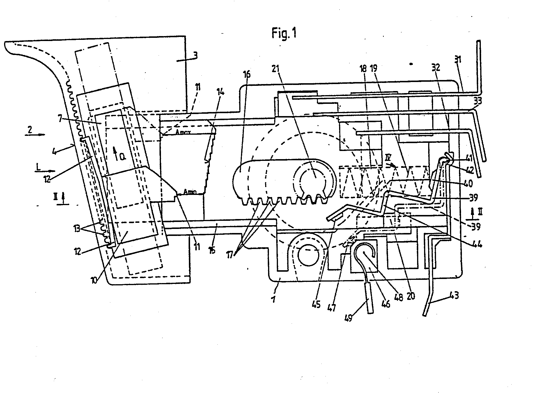
Description
Die Erfindung betrifft einen Schalter mit einer in einem Schaltergehäuse in Längsrichtung gegen die Kraft einer Feder verschiebbaren Taste, bei deren Verschiebebeginn eine elektrische Schaltbrücke schaltet und die einen veränderlichen Widerstand je nach dem Hub der Verschiebestrecke verstellt. Derartige Schalter werden in elektrischen Handwerkzeugmaschinen, insbesondere Handbohrmaschinen verwendet.The invention relates to a switch with a button that can be displaced in the longitudinal direction against the force of a spring in a switch housing, at the start of which an electrical switching bridge switches and which adjusts a variable resistance depending on the stroke of the displacement distance. Such switches are used in electrical hand machine tools, in particular hand drills.
Ein solcher Schalter ist in der DE-OS 28 38.934 beschrieben. Über die Schaltbrücke wird der Motor der Maschine eingeschaltet. Über den veränderlichen Widerstand, bzw. Potentiometer, läßt sich dessen Drehzahl verstellen. Bei dem in der DE-OS 28 38 934 gezeigten Schalter ist eine Arretierung der Taste nicht vorgesehen.Such a switch is described in DE-OS 28 38.934. The motor of the machine is switched on via the switching bridge. About the variable resistance, or Potentiometer, its speed can be adjusted. In the switch shown in DE-OS 28 38 934 a locking of the button is not provided.
Die Schaltbrücke der DE-OS 28 38 934 ist aufwendig aufgebaut. Denn sie benötigt zusätzlich zu.der die Taste rückstellenden Feder eine eigene Zugfeder. Außerdem muß ihr Gegenkontakt über eine elektrische Verbindung mit der betreffenden Anschlußklemme verbunden werden.The switching bridge of DE-OS 28 38 934 is complex. Because in addition to the spring resetting the button, it needs its own tension spring. In addition, their mating contact must be connected to the relevant terminal via an electrical connection.
In der DE-OS 28 38 934 wird ein Schleifer des veränderlichen Widerstands mit der Taste in Längsrichtung auf einer Widerstandsbahn verschoben. Damit ist der Verstellweg des Widerstandes gleich dem jeweiligen Tastenhub. Diese Abhängigkeit ist ungünstig, da der Tastenhub nach anderen Gesichtspunkten festgelegt wird, als der Verstellweg des Schleifers..In DE-OS 28 38 934 a grinder of variable resistance is moved with the key in the longitudinal direction on a resistance track. The adjustment path of the resistance is therefore equal to the respective key stroke. This dependency is unfavorable, since the key stroke is determined according to different criteria than the adjustment path of the grinder.
Ungünstig bei dem Schalter nach der DE-OS 28 38 934 ist außerdem, daß für den Benutzer keine Möglichkeit gegeben ist, sich den Widerstandswert und damit bei einer Bohrmaschine die Drehzahl, voreinzustellen, die bei einer Tastenbetätigung maximal erreicht werden soll. Beim Benutzer besteht der Wunsch zu einer solchen Voreinstellung, beispielsweise dann, wenn er an einem Material arbeitet, an dem eine bestimmte Arbeitsgeschwindigkeit der Maschine nicht überschritten werden soll. In der EP-FS 00 11 440 ist ein Schalter beschrieben, bei dem an der Taste ein Drehknopf angeordnet ist, durch den festzulegen ist, wie weit die Taste eingedrückt werden können soll.A disadvantage of the switch according to DE-OS 28 38 934 is also that there is no possibility for the user to preset the resistance value and thus the speed at a drilling machine, which is to be achieved at the maximum when a key is pressed. The user desires such a presetting, for example when he is working on a material on which a certain working speed of the machine should not be exceeded. EP-FS 00 11 440 describes a switch in which a rotary knob is arranged on the key, by means of which it can be determined how far the key should be able to be pressed.
Ein solcher Drehknopf an der Stirnseite der Taste ist praktisch nur zu bedienen, indem die Maschine abgestellt und aus ihrer Arbeitsstellung gebracht wird. Der Drehknopf wird für den Benutzer lästig, wenn er - wie bei - den meisten Arbeitsvorgängen nötig - die Taste längere Zeit gedrückt halten soll.Such a rotary knob on the front of the button can only be operated practically by switching off the machine and bringing it out of its working position. The rotary knob becomes annoying for the user if, as is necessary for most work processes, he has to hold the button down for a long time.
Aufgabe der Erfindung ist es, einen Schalter der eingangs genannten Art so aufzubauen, daß sich der Endanschlag der Taste ohne Drehknopf und ohne Beeinträchtigung der Funktion der Schaltbrücke einstellen läßt.The object of the invention is to construct a switch of the type mentioned in such a way that the end stop of the key can be set without a rotary knob and without impairing the function of the switching bridge.
Erfindungsgemäß ist obige Aufgabe bei einem Schalter der eingangs genannten Art dadurch gelost, daß an der Taste ein in Querrichtung verschiebbarer Schieber gelagert ist, der eine in der Längsrichtung vorstehende Anschlagkante aufweist, daß an dem Schaltergehäuse ein Anschlagrand vorgesehen ist, der der Anschlagkante zugewandt ist, und daß der Abstand der Anschlagkante von dem Anschlagrand in der Längsrichtung gesehen in einer Verschiebestellung des Schiebers größer als in einer anderen Verschiebestellung ist.According to the invention, the above object is achieved in a switch of the type mentioned at the outset in that a transversely displaceable slide is mounted on the button, which has a stop edge protruding in the longitudinal direction, and that a stop edge is provided on the switch housing which faces the stop edge, and that the distance of the stop edge from the stop edge seen in the longitudinal direction is greater in a sliding position of the slide than in another sliding position.
Durch Verschieben des Schiebers in Querrichtung läßt sich der mögliche Hub der Taste einstellen. Der Schieber ist einerseits leicht zu betätigen. Andererseits stört er beim Drücken der Taste nicht. Vorzugsweise ist der Schieber an einer Seitenfläche der Taste angeordnet. Damit bleibt die Stirnfläche der Taste glatt.The possible stroke of the button can be adjusted by moving the slide in the transverse direction. On the one hand, the slide is easy to operate. On the other hand, it does not interfere when the button is pressed. The slide is preferably arranged on a side surface of the key. This keeps the button face smooth.
In bevorzugter Ausgestaltung der Erfindung weist die Taste eine sich in Längsrichtung erstreckende Zahnreihe auf, in die ein Ritzel eingreift. An dem Ritzel ist ein Schleifer drehfest befestigt, der einer kreisbogenförmigen Widerstandsbahn zugeordnet ist. Durch diese Anordnung ist es möglich, eine Übersetzung in der Weise zu schaffen, daß einem bestimmten, kleinen Hub der Taste ein wesentlich größerer Verschiebeweg des Schleifers auf der Widerstandsbahn entspricht. Dies ist günstig, da dadurch die Belastbarkeit der Widerstandsschicht und die Wiederholungsgenauigkeit der Einstellung des vom Schleifer auf der Widerstandsbahn abgegriffene Widerstands verbessert ist. Begrenzt der Schieber also den Hub der Taste auf einen bestimmten Wert, dann wird immer wieder, wenn die Taste bis zum Anschlag betätigt wird, der gleiche Widerstandswert eingestellt. Es ist dadurch gewährleistet, daß beispielsweise bei einer bestimmten Schiebereinstellung die Bohrmaschine immer die gleiche Drehzahl erreicht, wenn die Taste bis zum Anschlag verschoben wird.In a preferred embodiment of the invention, the key has a row of teeth extending in the longitudinal direction, in which a pinion engages. A grinder is attached to the pinion in a rotationally fixed manner and is assigned to an arc-shaped resistance track. With this arrangement it is possible to create a translation in such a way that a certain, small stroke of the key corresponds to a much larger displacement path of the grinder on the resistance track. This is favorable because it improves the resilience of the resistance layer and the repetition accuracy of the setting of the resistance tapped by the grinder on the resistance track. If the slider limits the stroke of the key to a certain value, the same resistance value is set every time the key is pressed as far as it will go. This ensures that, for example, with a certain slide setting, the drilling machine always reaches the same speed when the key is moved as far as it will go.
In weiterer Ausgestaltung der Erfindung ist auf der Achse des Ritzels ein Druckknopf angeordnet, welcher an seinem Umfang eine Verzahnung aufweist, die einer Verzahnung des Schaltergehäuses gegenübersteht. Beim Ineinandergreifen verhaken die Verzahnungen unter der Wirkung der Feder, die die Taste zurückstellt. Wird in irgendeiner Stellung der Taste auf den Druckknopf gedrückt, dann greifen die Verzahnungen ineinander. Das Ritzel ist dadurch nicht mehr drehbar. Beim Loslassen der Taste drückt die Zahnreihe unter der Wirkung der Feder auf das Ritzel, wodurch die Verzahnung verhakt. Günstig ist dabei, daß das Feststellen der Taste in jeder Stellung unabhängig von der Einstellung des Schiebers möglich ist.In a further embodiment of the invention, a push button is arranged on the axis of the pinion, which has a toothing on its circumference that opposes a toothing of the switch housing. When meshing, the teeth interlock under the action of the spring that resets the button. If the button is pressed in any position, the teeth mesh. As a result, the pinion can no longer be rotated. When the button is released, the row of teeth press under the action the spring on the pinion, causing the teeth to get caught. It is favorable that the key can be locked in any position regardless of the setting of the slide.
Die Feder, die die Taste zurückstellt, übernimmt nicht nur die Rückstellfunktion, sondern dient, wie beschrieben, auch dem Verrasten der Taste. Darüber hinaus übernimmt die Feder auch die Betätigung der Schaltbrücke. Hierfür stützt sich die Feder der Taste gegenüber an einem ersten Ende der Schaltbrücke ab. An der Taste ist ein Nocken angeordnet, der die Schaltbrücke gegen die Kraft dieser Feder in ihrer einen Stellung hält. Bei Verschiebebeginn der Taste gibt die Nocke die Schaltbrücke frei, wobei diese unter der Kraft der Feder in ihre andere Schaltstellung klappt. Es erübrigt sich dabei eine zusätzliche eigene Feder für die Verschwenkung der Sohaltbrücke.The spring that resets the button not only takes over the reset function, but also serves, as described, to lock the button. In addition, the spring also operates the switching bridge. For this purpose, the spring of the button is supported opposite at a first end of the switching bridge. A cam is arranged on the button, which holds the switching bridge in its one position against the force of this spring. When the button begins to be displaced, the cam releases the switching bridge, which folds into its other switching position under the force of the spring. There is no need for an additional spring of its own for pivoting the bridge.
Weitere vorteilhafte Ausgestaltungen der Erfindung ergeben sich aus der folgenden Beschreibung eines Ausführungsbeispiels. In der Zeichnung zeigen :
Figur 1 eine Ansicht eines Schalters einer Bohrmaschine im Teilschnitt,Figur 2 eine Schnittansicht des Schalters längs der Linie II-II nachFigur 1,- Figur 3 eine Aufsicht auf eine Leiterplatte des Schalters, und
Figur 4 eine Ansicht einer Schaltbrücke des Schalters in Richtung des Pfeiles IV inFigur 1.
- FIG. 1 shows a view of a switch of a drilling machine in partial section,
- FIG. 2 shows a sectional view of the switch along the line II-II according to FIG. 1,
- Figure 3 is a plan view of a circuit board of the switch, and
- 4 shows a view of a switching bridge of the switch in the direction of arrow IV in FIG. 1.
In einem Schaltergehäuse 1 ist eine Taste 2,in Längsrichtung L verschieblich gelagert. Deren Tastenkopf 3 weist eine glatte, ununterbrochene Stirnfläche 4 und eine ebensolche Seitenfläche 5'auf. An der dieser gegenüberliegenden Seitenfläche 6 ist eine Ausnehmung 7 vorgesehen. Diese erstreckt sich in Richtung Q quer zur Längsrichtung L, parallel zur Stirnfläche 4.A
In der Ausnehmung 7 ist ein Schieber 8 verschieblich geführt, der eine Bedienplatte 9 aufweist, die bündig mit der Seitenfläche 6 liegt und an ihrer Oberfläche geriffelt ist. Mit der Bedienplatte 9 ist ein Schieberkörper 10 verbunden, der im Inneren des Tastenkopfes 3 liegt und eine in Längsrichtung L vorstehende Anschlagkante 11 aufweist. Am Schieberkörper 10 sind federnde Zungen 12 ausgebildet, welche in Rillen 13 rasten, die an der Innenseite der Stirnfläche 4 vorgesehen sind.In the recess 7, a slide 8 is slidably guided, which has an operating plate 9, which is flush with the side surface 6 and is corrugated on its surface. With the control panel 9, a
Am Gehäuse 1 ist ein abgetreppter Anschlagrand 14 ausgebildet, der der Anschlagkante 11 gegenübersteht. Bei der in Figur 1 mit durchgezogenen Linien gezeigten, untersten Stellung des Schiebers 8 nimmt der Abstand zwischen der Anschlagkante 11 und dem Anschlagrand 14 seinen Minimalwert Amin an. Bei der strichliert gezeigten, obersten Stellung des Schiebers 8 nimmt der Abstand zwischen der Anschlagkante 11 und dem Anschlagrand 14 seinen Maximalwert Amax an. Zwischen diesen beiden Grenzwerten ändert sich der Abstand stufenweise.A
Die Taste 2 weist einen Tastenkörper 15 auf, welcher in dem Schaltergehäuse 1 geführt ist. Der Tastenkörper 15 weist einen Durchbruch 16 auf, welcher an seiner einen Seite mit einer Zahnreihe 17 versehen ist, die sich in Längsrichtung L erstreckt. Am dem dem Tastenkopf 3 abgewandten Ende des Tastenkörpers 15 ist eine Höhlung 18 vorgesehen, in der eine Druckfeder 19 gelagert ist. Außerdem ist am Tastenkörper 15 eine Nocke 20 ausgebildet.The
In die Zahnreihe 17 greift ein Ritzel 21 ein. Auf dem Ritzel 21 ist drehfest ein Schleiferträger 22 angeordnet, der Schleiferfinger 23, 24 trägt. Diesen ist eine Leiterplatte 25 (vgl. Figur 3) zugeordnet. Auf die Leiterplatte 25 ist ein innerer Leitring 26 aufgedruckt. Auf diesem steht der Schleiferfinger 23 auf. Um den inneren Leitring 26 herum liegt kreisbogenförmig eine Widerstandsbahn 27, welche in Leitbeläge 28 und 29 ausläuft. Der innere Leitring 26 läuft in einen Leitbelag 30 aus. Auf der Widerstandsbahn 27 bzw. den Leitbelägen 28 und 29 stehen die Schleiferfinger 24 auf. Die Leitbeläge 28, 29 und 30 sind an Anschlußfahnen 31, 32 und 33 angeschlossen.A
Auf der Achse des Ritzels 21 ist außerhalb des Schaltergehäuses 1 an einem Vierkant 34 ein Druckknopf 35 gelagert. Dieser stützt sich mittels einer Druckfeder 36 gegen das Gehäuse 1 ab. Am Außenumfang des Druckknopfes 35 ist eine Säge-Verzahnung 37 ausgebildet, deren Zähne leicht hinterschnitten sind. Eine entsprechende Säge-Verzahnung 38 ist an dem Schaltergehäuse 1 ausgebildet.On the axis of the
An ihrem der Höhlung 18 gegenüberliegenden Ende steht die Druckfeder 19 auf einer Schaltbrücke 39 auf. Zur Führung der Feder 19 ist die Schaltbrücke 39 mit einem stumpfkegelförmigen Ansatz 40 versehen. Am einen Ende der Schaltbrücke 39 ist eine Abknickung 41 ausgebildet, welche in einer Auskehlung 42 einer Anschlußfahne 43 liegt. Die Schaltbrücke 39 weist eine Stufe 44 auf, mit deren Rand sie in der einen Schaltstellung lose auf der Nocke 20 aufsteht. Am anderen Ende der Schaltbrücke 39 ist eine Kontaktfläche 45 ausgebildet. In der Bewegungsbahn der Kontaktfläche 45 liegt ein Klemmstück 46, an dem eine Gegenkontaktfläche 47 ausgebildet ist. Das Klemmstück 46 weist eine Gewindebohrung 48 auf, in die eine nicht näher dargestellte Schraube zum Festziehen eines Anschlußdrahtes 49 zu schrauben ist.At its end opposite the
Die Anschlußfahne 43 und der Anschlußdraht 49 liegen an dem Elektromotor der Bohrmaschine bzw. dem Netzanschluß. In Figur 1 ist die offene Schaltstellung der Schaltbrücke 39 mit durchgezogenen Linien gezeigt. Die geschlossene Schaltstellung ist strichliert dargestellt. Der Schalter für den Elektromotor besteht aus nur drei Teilen, nämlich der Anschlußfahne 43, der Schaltbrücke 39 und dem Klemmstück 46.The connecting
An die Anschlußfahnen 31, 32 und 33 ist eine Drehzahl-Regelungseinrichtung der Bohrmaschine angeschlossen.A speed control device of the drilling machine is connected to the connecting
Die Funktionsweise des beschriebenen Schalters ist etwa folgende :
- Wird ausgehend von der in
den Figuren 1 und 2 dargestellten Ausschaltstellung auf dieStirnfläche 4 gedrückt, dann verschiebt sich dieTaste 2 entgegen der Kraft der Druckfeder 19 in Längsrichtung L. Dadurch gibt dieNocke 20 die Schaltbrücke 39 frei, so daß diese unter der Kraft der Druckfeder 19 so umklappt, daß ihre Kontaktfläche 45 auf dieGegenkontaktfläche 47 trifft. Es fließt jetzt Strom über dieAnschlußfahne 43, dieSchaltbrücke 39, das Klemmstück 46 undden Anschlußdraht 49, so daß die Bohrmaschine läuft. Gleichzeitig mit dem Drücken des Tastenkopfes 3 verschiebt sich auch die Zahnreihe 17, sodaß das Ritzel 21mit dem Schleiferträger 22 undden Schleiferfingern 23 und 24 verdreht wird. Zu Beginn dieser Drehung stehen dieSchleiferfinger 24 so auf der Widerstandsbahn 27, daß die Bohrmaschine mit minimaler Drehzahl läuft.
- If, starting from the switch-off position shown in FIGS. 1 and 2, the
end face 4 is pressed, then thebutton 2 moves against the force of thecompression spring 19 in the longitudinal direction L. As a result, thecam 20 releases the switchingbridge 39 so that it is under the force thecompression spring 19 so that itscontact surface 45 meets thecounter-contact surface 47. Current now flows through the connectinglug 43, the switchingbridge 39, the clamping piece 46 and the connectingwire 49, so that the drilling machine runs. Simultaneously with the pressing of the button head 3, the tooth row 17 also shifts, so that thepinion 21 is rotated with thegrinder carrier 22 and thegrinder fingers grinder fingers 24 are on theresistance track 27 in such a way that the drilling machine runs at minimum speed.
Im Zuge des weiteren Drückens des Tastenkopfes 3 dreht die Zahnreihe 17 das Ritzel 21 und damit den Schleiferträger 22 und die Schleiferfinger 23 und 24 weiter, so daß die Drehzahl der Bohrmaschine zunimmt.In the course of further pressing the button head 3, the row of teeth 17 rotates the
Ist der Schieber 8 so eingestellt, daß der Abstand seiner Anschlagkante 11 vom getreppten Anschlagrand 14 den kleinstmöglichen Wert (Amin) aufweist, dann läßt sich der Tastenkopf 3 nur um einen Teil seines Maximalhubes (Amax) verschieben. Wird der Tastenkopf 3 bis zu diesem Anschlag gedrückt, dann dreht die Zahnreihe 17 das Ritzel 21 und damit die Schleiferfinger 24 nur so weit, daß ein Bruchteil der Maximaldrehzahl zu erreichen ist. Der Benutzer kann also im voraus eine Minimaldrehzahl einstellen und trotzdem den Tastenkopf 3 bis zum Anschlag drücken. Stellt der Benutzer im Laufe des Bearbeitungsvorganges fest, daß die vorgewählte Drehzahl zu niedrig ist, dann kann er ohne Unterbrechung des Bearbeitungsvorganges die Bedienplatte 9 des Schiebers 8 mit dem Daumen der rechten Hand, deren Zeigefinger auf die Stirnfläche 4 drückt, in Richtung des Pfeiles Q vorschieben. Dadurch wird der Abstand zwischen der Anschlagkante 11 und dem getreppten Anschlagrand 14größer, so daß er bis zum neuerlichen Anschlagen über die Zahnreihe 17 das Ritzel 21 und damit die Schleiferfinger 24 weiter dreht, wodurch sich die Drehzahl der Maschine erhöht.Is the slider 8 set so that the distance of its
Die Anzahl der für eine der federnden Zungen vorgesehenen Rillen 13 ist gleich der Anzahl der Stufen des getreppten Anschlagrandes 14. Beim Verschieben des Schiebers 8 ergibt sich damit aufgrund der Rastwirkung der federnden Zungen 12 in den Rillen 13 eine stufenweise Verstellung. Dies erleichtert es dem Benutzer, die Drehzahl auf einen gewünschten Wert einzustellen. Außerdem ist verhindert, daß bei besonderer Leichtgängigkeit des Schiebers 8 unerwünschte Verstellungen der für einen Bearbeitungsvorgang gewählten Drehzahl stattfinden.The number of
Die Abtreppung des Anschlagrandes 14 ist so ausgelegt, daß der Benutzer bei laufender Maschine die Drehzahl durch Verschieben des Schiebers 8 nur erhöhen kann. Um eine niedrigere Drehzahl vorzuwählen, muß der Tastenkopf 3 losgelassen werden.The stepping of the
Im Beispielsfalle sind zehn Verstellstufen vorgesehen. 'Damit ist eine sehr feinstufige Anpassung der Drehzahl an die jeweiligen Erfordernisse möglich. Wird der Schieber 8 in die in Figur 1 strichliert dargestellte Endposition gebracht, dann kann durch mehr oder weniger starken Tastendruck zwischen der Minimaldrehzahl und der Maximaldrehzahl der Maschine variiert werden, ohne daß dies durch einen Anschlag-behindert ist.In the example, ten adjustment levels are provided. '' This enables a very fine adjustment of the speed to the respective requirements. If the slide 8 is brought into the end position shown in dashed lines in FIG. 1, the machine can be varied between the minimum speed and the maximum speed by pressing the button to a greater or lesser extent without this being impeded by a stop.
Die Hubdifferenz zwischen den Anschlagstellungen Amin und Amax muß nicht groß sein. Trotzdem wird ein großer Verstellbereich der Drehzahlen gewährleistet, weil der Weg, den die Schleiferfinger 24 bei einer Verstellung des Schiebers 8 von der Stellung Amin in die Stellung Amax wesentlich größer ist als die Hubdifferenz zwischen der Stellung Amin und Amax.The stroke difference between the stop positions Amin and Amax need not be large. Nevertheless, a large adjustment range of the rotational speeds is ensured because the path which the
Will der Benutzer bei länger dauernden Bearbeitungsvorgängen den Tastenkopf 3 arretieren und damit die Drehzahl festlegen, dann drückt er bei Erreichen der gewünschten Drehzahl den Druckknopf 35 gegen die Kraft der im Vergleich zur Druckfeder 19 schwachen Druckfeder 36, bis die Verzahnungen 37 und 38 ineinander greifen. Er läßt danach den Tastenkopf 3 los. Dadurch drückt die Druckfeder 19 über die Zahnreihe 17 auf das Ritzel 21, das sich dadurch um einen ganz geringfügigen Betrag so dreht, daß die Druckfeder 36 die hinterschnittenen Verzahnungen 37 und 38 nicht mehr außer Eingriff bringen kann. Damit sind die Stellung des Ritzels 21 und der Finger 24 und die Drehzahl fixiert. Die Verzahnungen 37 und 38 weisen mindestens ebenso viele Zähne auf, wie Treppenstufen an dem Anschlagrand 14 vorgesehen sind. Dadurch ist eine Drehzahlfixierung in gleicher Feinstufigkeit wie bei dauerndem Druck des Tastenkopfes 3 bis zum Anschlag gewährleistet.If the user wants to lock the button head 3 during longer machining operations and thus set the speed, then when the desired speed is reached, he presses the
Will der Benutzer die Fixierung lösen, dann drückt er auf die Stirnfläche 4. Dadurch wird über die Zahnreihe 17 und das Ritzel 21 die Verzahnung 37 des Druckknopfes 35 verdreht, so daß sie unter der Kraft der Druckfeder 36 außer Eingriff von der Verzahnung 38 kommt.If the user wants to release the fixation, he presses on the
Im Ausführungsbeispiel wird beim Drücken des Druckknopfes 35 auch das Ritzel 21 verschoben. Bei dieser Verschiebung bleibt die Verzahnung des Ritzels 21 im Eingriff mit der Zahnreihe 17. Der Schleiferträger 22 verschiebt sich dabei nicht, da er mit entsprechenden Zähnen in die Verzahnung des Ritzels 21 eingreift. Diese Kopplung der Verschiebung des Druckknopfes 35 und des Ritzels 21 stört nicht, kann jedoch durch geeignete Mittel umgangen werden.In the exemplary embodiment, the
Läßt der Benutzer den Tastenkopf 3 los, wenn die Verzahnungen 37 und 3.8 nicht ineinander greifen, dann wird unter der Kraft der Druckfeder 19 die Taste 2 in ihrer Ausgangsstellung geschoben. Über die Zahnreihe 17 werden dabei das Ritzel 21 und die Schleiferfinger 24 zurückgedreht und die Drehzahl reduziert. Schließlich trifft die Nocke 20 auf die Stufe 44 der Schaltbrücke 39, so daß sich deren Kontaktfläche 45 von dem Klemmstück 46 löst. Die Maschine ist damit abgeschaltet.The user lets go of the button head 3 if the toothings 37 and 3.8 do not interlock, then under the force of the
Der Druckknopf 35 dreht sich mit dem Ritzel 21 mit. Bei der in der Figur dargestellten Anordnung, bei der die Zahnreihe 17 unten liegt, dreht sich der Druckknopf 35 beim Drücken des Tastenkopfes 3 entgegen dem Uhrzeigersinn. Wird die Zahnreihe 17 nach oben gelegt, dann dreht sich der Druckknopf 35 beim Drücken des Tastenkopfes 3 im Uhrzeigersinn. Vorzugsweise ist am Umfang des Druckknopfes 35 eine nicht näher dargestellte Markierung angeordnet und am Umfang einer Durchbrechung des Maschinengehäuses, durch das der Druckknopf 35 ragt, ist eine entsprechende Skala, beispielsweise von "0" bis "6" vorgesehen. Das Mitdrehen des Druckknopfes 35 ist dadurch zur Anzeige der jeweiligen Drehzahl ausgenutzt. Der Benutzer kann an der Stellung der Markierung des Druckknopfes 35 die jeweils erreichte Drehzahl abschätzen. Eine weitere ähnliche Skala kann bei dem getreppten Anschlagrand 14 vorgesehen sein. Dies erleichert dem Benutzer die Vorwahl einer gewünschten Drehzahl durch Einstellung des Schieberkörpers 10. Eine solche Skala kann auch am Tastenkopf 3 neben dem Schieber 8 ausgebildet sein.The
Der beschriebene Schalter ist weitgehend staubdicht. Um die Staubdichtigkeit im Bereich des Druckknopfes 35 zu verbessern, ist vorzugsweise die Feder 36 mit einer Kunststoffhülle aus einem weichen Kunststoff umspritzt.The switch described is largely dustproof. In order to improve the dust-tightness in the area of the
Der Anschlagrand 14 muß nicht unbedingt getreppt sein. Er kann,auch einen kontinuierlichen Verlauf haben. Es kann auch der variable Abstand zwischen Anschlagkante 11 und Anschlagrand 14 dadurch erreicht werden, daß an dem Schieber 8 eine getreppt oder kontinuierlich abfallende Anschlagfläche vorgesehen und am Schaltergehäuse 1 ein fester Anschlagpunkt ausgebildet ist.The
Die beschriebene Anordnung der Schaltbrücke 39 kann auch bei anderen als den beschriebenen Schalter verwendet werden.The arrangement of the switching
Claims (12)
Applications Claiming Priority (2)
| Application Number | Priority Date | Filing Date | Title |
|---|---|---|---|
| DE19833342474 DE3342474A1 (en) | 1983-11-24 | 1983-11-24 | COUNTER |
| DE3342474 | 1983-11-24 |
Publications (2)
| Publication Number | Publication Date |
|---|---|
| EP0144591A2 true EP0144591A2 (en) | 1985-06-19 |
| EP0144591A3 EP0144591A3 (en) | 1986-09-17 |
Family
ID=6215137
Family Applications (1)
| Application Number | Title | Priority Date | Filing Date |
|---|---|---|---|
| EP84111682A Withdrawn EP0144591A3 (en) | 1983-11-24 | 1984-09-29 | Adjustable switching device |
Country Status (3)
| Country | Link |
|---|---|
| US (1) | US4660019A (en) |
| EP (1) | EP0144591A3 (en) |
| DE (1) | DE3342474A1 (en) |
Cited By (1)
| Publication number | Priority date | Publication date | Assignee | Title |
|---|---|---|---|---|
| EP0342327A1 (en) * | 1988-05-10 | 1989-11-23 | KAUTT & BUX KG | Apparatus switch |
Families Citing this family (15)
| Publication number | Priority date | Publication date | Assignee | Title |
|---|---|---|---|---|
| EP0157186B1 (en) * | 1984-04-03 | 1990-01-10 | Preh-Werke GmbH & Co. KG | Locking slide switch |
| JPS63170903U (en) * | 1987-04-28 | 1988-11-07 | ||
| US4968922A (en) * | 1988-04-15 | 1990-11-06 | Lucerne Products, Inc. | Reversing switch |
| DE4410312C2 (en) * | 1994-03-25 | 2000-01-13 | Bosch Gmbh Robert | Electric hand tool with potentiometer and method for adjusting the potentiometer |
| DE102004027644A1 (en) * | 2004-06-05 | 2006-06-08 | Robert Bosch Gmbh | Operating device of a power tool |
| JP4696670B2 (en) * | 2005-05-02 | 2011-06-08 | オムロン株式会社 | Trigger switch |
| NL1030893C2 (en) * | 2006-01-11 | 2007-07-12 | Electrische App Nfabriek Capax | As a switch with movement restriction for electrical hand tool |
| US9246487B2 (en) | 2008-12-16 | 2016-01-26 | Dell Products Lp | Keyboard with user configurable granularity scales for pressure sensitive keys |
| US9321112B2 (en) | 2011-05-18 | 2016-04-26 | Black & Decker Inc. | Power saw tool |
| US9368300B2 (en) | 2013-08-29 | 2016-06-14 | Dell Products Lp | Systems and methods for lighting spring loaded mechanical key switches |
| US9343248B2 (en) * | 2013-08-29 | 2016-05-17 | Dell Products Lp | Systems and methods for implementing spring loaded mechanical key switches with variable displacement sensing |
| US9559628B2 (en) | 2013-10-25 | 2017-01-31 | Black & Decker Inc. | Handheld power tool with compact AC switch |
| DE102018113100A1 (en) * | 2018-06-01 | 2019-12-05 | Elrad International D.O.O. | Switch for an electrical appliance |
| WO2020142894A1 (en) * | 2019-01-08 | 2020-07-16 | 深圳拓邦股份有限公司 | Electronic device, pcb board, and power tool |
| CN112057091B (en) * | 2020-08-18 | 2021-08-03 | 北京唯迈医疗设备有限公司 | Speed-regulating hand brake mechanism and speed-regulating method thereof |
Family Cites Families (13)
| Publication number | Priority date | Publication date | Assignee | Title |
|---|---|---|---|---|
| DE689194C (en) * | 1938-05-15 | 1940-03-13 | Stotz Kontakt Gmbh | Installation rotary switch |
| US3439248A (en) * | 1966-01-04 | 1969-04-15 | Singer Co | Trigger-actuated motor speed control and switching device having multiple selective positions for setting motor speeds |
| US3548136A (en) * | 1968-05-29 | 1970-12-15 | Skil Corp | Trigger actuated switch device with adjustment means for establishing a plurality of predetermined trigger positions |
| DE2012748B1 (en) * | 1970-03-18 | 1971-08-12 | Fa Heinrich Kopp | Electrical push button with thermal overcurrent release |
| US3713070A (en) * | 1971-05-03 | 1973-01-23 | Lucerne Products Inc | Rotary actuator for a switch |
| US3842328A (en) * | 1972-03-01 | 1974-10-15 | Skil Corp | Speed control device with independent speed control and on-off operating members |
| US3927276A (en) * | 1974-05-03 | 1975-12-16 | Mallory & Co Inc P R | Switch assembly with limit stop structure allowing alternate make and break operational switch states |
| US4137490A (en) * | 1977-11-08 | 1979-01-30 | Cutler-Hammer, Inc. | Trigger speed control switch |
| DE2838934C2 (en) * | 1978-09-07 | 1986-07-31 | J. & J. Marquardt, 7201 Rietheim-Weilheim | Electric switch |
| US4241297A (en) * | 1978-11-20 | 1980-12-23 | Eaton Corporation | Double-pole trigger speed control switch |
| DE3039614A1 (en) * | 1980-10-21 | 1982-05-19 | Brown, Boveri & Cie Ag, 6800 Mannheim | Slide movement hand operated switch - has protected keyway staggered profile movement slot to prevent ingress of dirt |
| DE3114794A1 (en) * | 1981-04-11 | 1982-10-28 | Merit-Werk Merten & Co Kg, 5270 Gummersbach | Switch having a rotary resistor or rheostat for regulating electrical loads for motor vehicles |
| DE3121033C2 (en) * | 1981-05-27 | 1986-06-26 | Marquardt Gmbh, 7201 Rietheim-Weilheim | Electrical switch and procedure for assembling the switch |
-
1983
- 1983-11-24 DE DE19833342474 patent/DE3342474A1/en active Granted
-
1984
- 1984-09-29 EP EP84111682A patent/EP0144591A3/en not_active Withdrawn
- 1984-11-15 US US06/671,632 patent/US4660019A/en not_active Expired - Fee Related
Cited By (1)
| Publication number | Priority date | Publication date | Assignee | Title |
|---|---|---|---|---|
| EP0342327A1 (en) * | 1988-05-10 | 1989-11-23 | KAUTT & BUX KG | Apparatus switch |
Also Published As
| Publication number | Publication date |
|---|---|
| DE3342474A1 (en) | 1985-06-13 |
| EP0144591A3 (en) | 1986-09-17 |
| US4660019A (en) | 1987-04-21 |
| DE3342474C2 (en) | 1987-10-01 |
Similar Documents
| Publication | Publication Date | Title |
|---|---|---|
| DE3342474C2 (en) | ||
| DE2838934C2 (en) | Electric switch | |
| DE19913712A1 (en) | Electric switch for electric handtool e.g. electric drill | |
| DE2648818C3 (en) | Torque-dependent switching device for an electric motor | |
| DE19505737C1 (en) | Cam switch | |
| DE2020557C3 (en) | Electrical device switch | |
| DE2512900C3 (en) | Selection for program switchgear | |
| EP0585541B1 (en) | Electric switch for speed control of motors | |
| EP0109544B1 (en) | Locking device for a drawer | |
| DE3512665A1 (en) | ELECTRIC SWITCH | |
| DE8013074U1 (en) | Additional switch for an adjustment device | |
| EP0157186B1 (en) | Locking slide switch | |
| EP0038287B1 (en) | Rotary handle for manual control of a power drive | |
| EP0038291B1 (en) | Motor drive for low-voltage protective switch | |
| DE1142935B (en) | Push button switches, especially for the control of machine tools | |
| DE3443323A1 (en) | PROGRAM SWITCHGEAR WITH A CLEARANCE CONTROL | |
| DE3112199A1 (en) | ROTARY DIALER DEVICE | |
| DE69105776T2 (en) | Switch. | |
| DE19946601C1 (en) | Switching device, in particular for a gas boiler | |
| DE3421670C2 (en) | ||
| DE2047758C3 (en) | Actuating device, in particular for an electrical switch, with an actuating member that can be locked by a latching device | |
| EP0690463B1 (en) | Child-proof switching device | |
| EP0029489A2 (en) | Key switch | |
| DE1591354C (en) | Key channel selection unit | |
| DE1440869C (en) | Push button switch |
Legal Events
| Date | Code | Title | Description |
|---|---|---|---|
| PUAI | Public reference made under article 153(3) epc to a published international application that has entered the european phase |
Free format text: ORIGINAL CODE: 0009012 |
|
| AK | Designated contracting states |
Designated state(s): AT BE CH FR GB IT LI NL SE |
|
| PUAL | Search report despatched |
Free format text: ORIGINAL CODE: 0009013 |
|
| AK | Designated contracting states |
Kind code of ref document: A3 Designated state(s): AT BE CH FR GB IT LI NL SE |
|
| STAA | Information on the status of an ep patent application or granted ep patent |
Free format text: STATUS: THE APPLICATION IS DEEMED TO BE WITHDRAWN |
|
| 18D | Application deemed to be withdrawn |
Effective date: 19870318 |
|
| RIN1 | Information on inventor provided before grant (corrected) |
Inventor name: BAUER, KARL-HEINZ Inventor name: RUTTERSCHMIDT, FRANZ Inventor name: SPILLER, GERHARD |