EP0144539B1 - Shutter mechanism - Google Patents
Shutter mechanism Download PDFInfo
- Publication number
- EP0144539B1 EP0144539B1 EP84109954A EP84109954A EP0144539B1 EP 0144539 B1 EP0144539 B1 EP 0144539B1 EP 84109954 A EP84109954 A EP 84109954A EP 84109954 A EP84109954 A EP 84109954A EP 0144539 B1 EP0144539 B1 EP 0144539B1
- Authority
- EP
- European Patent Office
- Prior art keywords
- gate
- carrier plate
- plate
- gate control
- control member
- Prior art date
- Legal status (The legal status is an assumption and is not a legal conclusion. Google has not performed a legal analysis and makes no representation as to the accuracy of the status listed.)
- Expired
Links
- 230000007246 mechanism Effects 0.000 title description 16
- 230000033001 locomotion Effects 0.000 claims description 6
- 238000007373 indentation Methods 0.000 description 5
- 238000007789 sealing Methods 0.000 description 4
- 230000003287 optical effect Effects 0.000 description 3
- 238000005033 Fourier transform infrared spectroscopy Methods 0.000 description 2
- 239000007789 gas Substances 0.000 description 2
- 238000000034 method Methods 0.000 description 2
- 230000002093 peripheral effect Effects 0.000 description 2
- 238000010926 purge Methods 0.000 description 2
- 230000000717 retained effect Effects 0.000 description 2
- 239000003566 sealing material Substances 0.000 description 2
- 229920000049 Carbon (fiber) Polymers 0.000 description 1
- UCKMPCXJQFINFW-UHFFFAOYSA-N Sulphide Chemical compound [S-2] UCKMPCXJQFINFW-UHFFFAOYSA-N 0.000 description 1
- 238000005299 abrasion Methods 0.000 description 1
- DHKHKXVYLBGOIT-UHFFFAOYSA-N acetaldehyde Diethyl Acetal Natural products CCOC(C)OCC DHKHKXVYLBGOIT-UHFFFAOYSA-N 0.000 description 1
- 125000002777 acetyl group Chemical class [H]C([H])([H])C(*)=O 0.000 description 1
- 230000005540 biological transmission Effects 0.000 description 1
- 239000004917 carbon fiber Substances 0.000 description 1
- 230000003749 cleanliness Effects 0.000 description 1
- 230000005494 condensation Effects 0.000 description 1
- 238000009833 condensation Methods 0.000 description 1
- 238000011109 contamination Methods 0.000 description 1
- 238000007796 conventional method Methods 0.000 description 1
- 230000000593 degrading effect Effects 0.000 description 1
- 239000006260 foam Substances 0.000 description 1
- 239000011261 inert gas Substances 0.000 description 1
- 238000004519 manufacturing process Methods 0.000 description 1
- 239000000463 material Substances 0.000 description 1
- VNWKTOKETHGBQD-UHFFFAOYSA-N methane Chemical compound C VNWKTOKETHGBQD-UHFFFAOYSA-N 0.000 description 1
- 230000035945 sensitivity Effects 0.000 description 1
Images

Classifications
-
- F—MECHANICAL ENGINEERING; LIGHTING; HEATING; WEAPONS; BLASTING
- F16—ENGINEERING ELEMENTS AND UNITS; GENERAL MEASURES FOR PRODUCING AND MAINTAINING EFFECTIVE FUNCTIONING OF MACHINES OR INSTALLATIONS; THERMAL INSULATION IN GENERAL
- F16K—VALVES; TAPS; COCKS; ACTUATING-FLOATS; DEVICES FOR VENTING OR AERATING
- F16K3/00—Gate valves or sliding valves, i.e. cut-off apparatus with closing members having a sliding movement along the seat for opening and closing
- F16K3/02—Gate valves or sliding valves, i.e. cut-off apparatus with closing members having a sliding movement along the seat for opening and closing with flat sealing faces; Packings therefor
- F16K3/04—Gate valves or sliding valves, i.e. cut-off apparatus with closing members having a sliding movement along the seat for opening and closing with flat sealing faces; Packings therefor with pivoted closure members
- F16K3/10—Gate valves or sliding valves, i.e. cut-off apparatus with closing members having a sliding movement along the seat for opening and closing with flat sealing faces; Packings therefor with pivoted closure members with special arrangements for separating the sealing faces or for pressing them together
-
- Y—GENERAL TAGGING OF NEW TECHNOLOGICAL DEVELOPMENTS; GENERAL TAGGING OF CROSS-SECTIONAL TECHNOLOGIES SPANNING OVER SEVERAL SECTIONS OF THE IPC; TECHNICAL SUBJECTS COVERED BY FORMER USPC CROSS-REFERENCE ART COLLECTIONS [XRACs] AND DIGESTS
- Y10—TECHNICAL SUBJECTS COVERED BY FORMER USPC
- Y10T—TECHNICAL SUBJECTS COVERED BY FORMER US CLASSIFICATION
- Y10T74/00—Machine element or mechanism
- Y10T74/18—Mechanical movements
- Y10T74/18856—Oscillating to oscillating
Definitions
- the present invention generally relates to a gate valve control means; actuating means of said gate control means; a gate carrier plate carrying a gate plate, the gate control means rotating said gate carrier plate from a first position, whereat a port through a wall is fully open, to a second position, whereat the gate plate faces said port, interlocking means between said gate carrier plate and said gate control means are provided while the gate carrier plate is moved between said first and said second position, releasing means of the gate carrier plate from the gate control means and engaging means between the gate plate and the gate control means are provided when the gate carrier plate is in said second position and when the gate control means is further actuated, so that the gate plate moves relatively to the gate carrier plate and covers sealingly the port.
- the invention in particular, relates to a gate valve which ensures that the sealing/unsealing movement and the rotational movement of the gate plate are mutually exclusive.
- FT/IR Fourier Transform Infrared
- the said gate valve includes a gate plate which is carried by a gate plate carrier.
- the gate plate carrier is connected via a linkage, which forms a gate control means with an actuating means for pivoting the gate plate carrier from a first open position into a second position in which the valve plate may cover a port.
- the actuating means is actuated in order to move the gate valve from an open position to a closed position the linkage is interlocked with the gate carrier plate so that the gate carrier plate may be moved from a first to a second position in which the gate carrier plate abuts against an abuttment.
- the linkage is pivoted with respect to the fixedly positioned gate carrier plate and turns a screw assembly so that the gate plate is displaced in its axial direction relative to the gate carrier plate.
- a gate valve of the above-mentioned type which is characterized in that the gate control means consists of a pivotable gate control member, that the gate plate is held by one end of a pivot arm being pivotably mounted on the gate carrier plate and that the engaging means comprises a ramp provided on the gate control member and which engages the arm at its other end of the further movement of the gate control member to pivot the gate plate into a sealed port covering position.
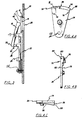
- a gate mechanism generally indicated at 10 in the drawing and embodying the principles of the present invention, includes a gate plate 12 having an annulus 14 of resilient sealing material affixed to one face 16 thereof (Fig. 3). The opposite face 20 of plate 12 is affixed to one end of a gate arm 18 by means of a universal joint.
- the gate mechanism 10 also includes a gate arm carrier plate 22 to which the gate arm 18 is pivotably affixed. Further included in mechanism 10 is a gate control member 24 rotatable between a first position 26 (Fig. 1), whereat a port 28 through a wall 30 (e.g. a sample compartment wall is fully opened, and a second position 32 (Fig. 2), whereat the port 28 is sealed by the gate. plate 12.
- the mechanism 10 further includes a means 34 for interlocking the gate arm carrier plate 22 with the gate control member 24 only during a first portion of the distance rotated between the first position and the second position.
- the gate mechanism 10 includes a means 36 for releasing the gate arm carrier plate 22 from the gate control member 24 during a second portion of the distance translated between the first position and the second position.
- the gate mechanism 10 includes means 38 for pivoting the gate arm 18 only during the second portion of the total distance rotated between the first position and the second position.
- the mechanism 10 is located within the optical compartment of a Fourier Transform Infrared (FT/IR) spectrophotometer adjacent the sample compartment wall 30.
- FT/IR Fourier Transform Infrared
- a number of ports 28, only one of which is shown in Figure 1, through the wall 30 are about 40 mm in diameter and are situated to allow the incident beam to enter and exit the sample compartment.
- the gate plate 12 in one embodiment, has an outside diameter of about 5 centimeters and the annulus 14 of sealing material, e.g. foam, affixed to the face 16 thereof, has a thickness of about 0.3 centimeters and an outside radius of about 2.5 centimeters.
- the gate plate 12 is connected to one end 40 of the gate arm 18 by means of, for examqle, a ball and socket joint which allows uniform pressure to be applied against the wall 30 by the gate plate 12 when in the closed position.
- gate arm 18 is pivotably secured to the gate arm carrier plate 22.
- gate arm carrier plate 22 is generally formed in the shape of a circular sector and includes a tab 42, preferably rectangular, extending from the sector arc 44 away from the pivot point.
- the gate arm 18 is secured between a pair of pins 46 about which it can rotate, which pins are affixed to a pair of blocks 48 protruding from the tab 42.
- the other end 50 of the arm 18, in the preferred embodiment carries a roller bearing 52 which is in the shape of a cone segment.
- the bearing 52 rotates in an opening 54 in end 50 of the arm 18 and protrudes slightly therefrom. As more fully discussed below, the bearing 52 acts in conjunction with a ramp 56 protruding from the gate control member 24 to cause end 40 of the gate arm 18 to pivot toward the wall 30.
- the gate arm carrier plate 22 shown in Figures 5A through 5C, is rotatably affixed to the sample compartment wall 30.
- the gate arm carrier plate 22 is a sector having an included angle of 70 degrees and bounded by radii of about 6 centimeters.
- the gate arm carrier plate 22 rotates about a point 58 which is located along a radius bisecting the included angle.
- the sector arc 44 includes a first portion 60 of about 45 degrees and a second portion 62 of about 25 degrees.
- the first portion 60 is bounded by radii of about 6 centimeters and the second portion 62 is bounded by radii of about 5 centimeters.
- the first portion 60 and the second portion 62 interface at an angle of about 45 degrees near the arc periphery to form a first notch 64.
- the first portion 60 of the carrier plate 22 includes a protruding rim 66 along the arc thereof which rim 66 includes a gap 68 therein.
- the protruding rim 66 includes a rim extension 70 extending along the sector boundary radius downwardly away from the arc 44.
- the rim extension 70 extends along the radius a distance of about 1 centimeter.
- the rim extension 70 serves as part of the means 34 for interlocking the gate arm carrier plate 22 and the gate control member 24.
- the gate control member 24, shown in Figures 4A through 4C, is rotatably affixed to the sample compartment wall 30 and spaced apart therefrom by the shutter carrier plate 22.
- the gate control member 24 is also a sector having an included angle of about 30 degrees and bounded by radial edges 74 of about 5.5 centimeters in length.
- the gate control member 24 rotates about point 58 on a radius bisecting the included angle.
- the gate control member 24 and the gate arm carrier plate 22 rotate about a common axis at point 58.
- the gate control member 24 has a first surface 76 proximate the wall 30 and an opposing surface 78 generally parallel to and spaced apart from the first surface 76.
- the gate control member 24 is about 1 centimeter thick.
- the first surface 76 includes an indentation 80 therein which extends into the first surface 76 to a depth of about 0.3 centimeters and arcuately extends from one edge 82 of the member 24 about 14 degrees.
- the indentation 80 forming a segment 81 of the sector, uniformly extends away from the sector arc 74 about 0.25 centimeters to provide a release track 84.
- the member 24 further includes the gate arm engaging ramp 56 protruding from the second face 78 thereof.
- the ramp 56 extends about 15 degrees arcuately and rises from a zero depth at one end 86 to a thickness of about 0.4 centimeters at the other end 88.
- the other end 88 of the ramp 56 co-terminates with the radius of the sector distal the identation 80.
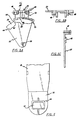
- a retainer plate 90 is provided and affixed to the wall 30.
- the retainer plate 90 is affixed such that the tab 42 of the gate arm carrier plate 22 extends above the outer peripheral edge 92 thereof. Additionally, sufficient clearance is provided to allow the carrier plate 22 to rotate.
- the retainer plate 90 includes an arcuate track 94 which is substantially uniformly spaced apart from the protruding rim 66 of the gate carrier plate 22.
- the track 94 includes an interlocking means receiving notch 96 therein having an arcuate length of about 15 degrees and a depth of about 0.2 centimeters.
- the track 94 includes a downwardly protruding stop 98 at one end thereof proximate the notch 96.
- the retainer plate 90 includes an overhanging lip 100, which is, for clarity, shown in cutaway only in Figure 2, and which, for reasons more fully explained below, overhangs the gate control member 24.
- All the components of the mechanism 10 can be formed using conventional manufacturing techniques.
- the parts hereof are formed 40% carbon fiber filled polyphenelene sulfide except for the conical bearing 52 which is preferably formed from acetal.
- a disk 102 having a diameter on the order of about 0.65 centimeters and a thickness on the order of about 0.3 centimeters, effectively constitutes the interlocking means 34.
- the disk 102 is positioned in the indentation 80 in the gate control member 24 and projects into the gap 68 in the protruding rim 66 of the sample carrier plate 22 during the rotation of the gate control member 24 through the first portion of the complete distance of its travel.
- the gate control member 24 is affixed to a movable arm 104 which causes it to rotate about its pivot point 58.
- the moveable arm 104 is controlled by a pneumatic piston although other forms of movement such as a reciprocating motor or the like could also be used.
- Figure 1 which represents the gate mechanism 10 being in the fully opened position
- the disk 102 is retained between the indentation 80 in the shutter control member 24 and in the gap 68 of the gate carrier plate 22.
- the control member 24 is urged to rotate by the moving arm 104
- the gate carrier plate 22 is carried therewith.
- the member 24 and the plate 22 remain interlocked until the notch 96 in the retainer plate 90 is reached whereupon the downwardly protruding edge 98 of the retainer plate 90 stops any further rotation of the gate carrier member 22.
- the disk 102 is, at that point in time, aligned with the notch 96 extending into the retainer plate 90 and is pushed thereinto by the continued rotation of the gate control member 24.
- the control member 24 is allowed to continue its rotation whereas the gate carrier member 22 is retained in position.
- the conical bearing 52 of the gate arm 18 contacts the ramp 56 protruding from the second surface 78 of the control member 24 and, as the rotation continues, pivots the gate plate 12 toward the port 28.
- the conical bearing 52 is at approximately the maximum height of the ramp 56 thereby providing maximum force to the gate plate 12 against the wall 30 about the port 28.
- the disk 102 is secured in the notch 96 of the retainer plate 90 by the outer peripheral arc 74 of the control member 24.
- the control member 24 When the port 28 is to be opened, the control member 24 is rotated clockwise to thereby remove the ramp 56 from underneath the conical bearing 52 and allow the gate plate 12 to move away from the port 28. At this stage, i.e. once the conical bearing 52 is released from the ramp 56, the disk 102 moves through the gap 68 of the protruding rim 66 carrier plate 22 into the indentation 80 of the control member 24. Simultaneously, the control member 24 contacts the rim extension 70 protruding downwardly along the radius of the carrier plate 22 and causes the carrier plate 22 to rotate with the control member 24.
Landscapes
- Engineering & Computer Science (AREA)
- General Engineering & Computer Science (AREA)
- Mechanical Engineering (AREA)
- Sliding Valves (AREA)
- Automatic Analysis And Handling Materials Therefor (AREA)
- Preventing Unauthorised Actuation Of Valves (AREA)
- Investigating Or Analysing Materials By Optical Means (AREA)
Applications Claiming Priority (2)
| Application Number | Priority Date | Filing Date | Title |
|---|---|---|---|
| US06/549,952 US4603835A (en) | 1983-11-09 | 1983-11-09 | Shutter mechanism |
| US549952 | 1983-11-09 |
Publications (3)
| Publication Number | Publication Date |
|---|---|
| EP0144539A2 EP0144539A2 (en) | 1985-06-19 |
| EP0144539A3 EP0144539A3 (en) | 1986-01-02 |
| EP0144539B1 true EP0144539B1 (en) | 1989-08-09 |
Family
ID=24195080
Family Applications (1)
| Application Number | Title | Priority Date | Filing Date |
|---|---|---|---|
| EP84109954A Expired EP0144539B1 (en) | 1983-11-09 | 1984-08-21 | Shutter mechanism |
Country Status (4)
Families Citing this family (7)
| Publication number | Priority date | Publication date | Assignee | Title |
|---|---|---|---|---|
| JPS63312583A (ja) * | 1987-06-12 | 1988-12-21 | Matsushita Electric Ind Co Ltd | 圧電弁 |
| JPS63312582A (ja) * | 1987-06-12 | 1988-12-21 | Matsushita Electric Ind Co Ltd | 圧電弁 |
| US5172643A (en) * | 1990-07-16 | 1992-12-22 | Oki Electric Industry Co., Ltd. | Apparatus for handling strips of paper |
| US5931178A (en) * | 1996-03-19 | 1999-08-03 | Design Systems, Inc. | High-speed water jet blocker |
| US5944300A (en) * | 1998-06-05 | 1999-08-31 | Macmillan Bloedel Packaging | Bag and box valve system |
| US6752373B1 (en) * | 2001-12-18 | 2004-06-22 | Fmc Technologies, Inc. | High-speed fluid jet blocker |
| EP2416187B1 (en) * | 2010-08-04 | 2013-05-08 | HORIBA, Ltd. | Air-driven shutter device and optical analyzer |
Family Cites Families (8)
| Publication number | Priority date | Publication date | Assignee | Title |
|---|---|---|---|---|
| US521832A (en) * | 1894-06-26 | Steam-radiator | ||
| DE180936C (GUID-C5D7CC26-194C-43D0-91A1-9AE8C70A9BFF.html) * | 1906-05-02 | |||
| CH331645A (fr) * | 1955-01-07 | 1958-07-31 | Foltzer Marcel | Dispositif de fermeture à tiroirs de conduites de fluide sous pression |
| US3237916A (en) * | 1963-10-02 | 1966-03-01 | Grove Valve & Regulator Co | Disc valve |
| FR1413258A (fr) * | 1964-09-30 | 1965-10-08 | Grove Valve & Regulator Compan | Vanne à disque |
| US3343562A (en) * | 1965-01-15 | 1967-09-26 | Grove Valve & Regulator Co | Pivoted valve construction |
| US3521665A (en) * | 1968-05-09 | 1970-07-28 | Alden Poulsen | Gate valve |
| US4062515A (en) * | 1976-05-13 | 1977-12-13 | The United States Of America As Represented By The United States Energy Research And Development Administration | Compact gate valve |
-
1983
- 1983-11-09 US US06/549,952 patent/US4603835A/en not_active Expired - Lifetime
-
1984
- 1984-08-21 EP EP84109954A patent/EP0144539B1/en not_active Expired
- 1984-08-21 DE DE8484109954T patent/DE3479331D1/de not_active Expired
- 1984-11-09 JP JP59235375A patent/JPS60121378A/ja active Granted
Also Published As
| Publication number | Publication date |
|---|---|
| EP0144539A2 (en) | 1985-06-19 |
| EP0144539A3 (en) | 1986-01-02 |
| DE3479331D1 (en) | 1989-09-14 |
| JPS60121378A (ja) | 1985-06-28 |
| US4603835A (en) | 1986-08-05 |
| JPH0456915B2 (GUID-C5D7CC26-194C-43D0-91A1-9AE8C70A9BFF.html) | 1992-09-09 |
Similar Documents
| Publication | Publication Date | Title |
|---|---|---|
| EP0144539B1 (en) | Shutter mechanism | |
| US4901173A (en) | Apparatus for coupling record disk to disk drive | |
| JP5324827B2 (ja) | 脚部要素を有する真空ゲートバルブ | |
| US3690244A (en) | Air valve with fan actuator | |
| GB2126684A (en) | Closure for a pressurized chamber | |
| GB2116680A (en) | Slide valve | |
| EP0973163A3 (en) | Disc cartridge | |
| US4515286A (en) | Cap and a cap opening and closing device | |
| CA2061132A1 (en) | Sampling valve | |
| JPH0766768B2 (ja) | 粒子線を用いた表面分析装置 | |
| US4291313A (en) | Recording apparatus | |
| US5247416A (en) | Disk cartridge with friction-reducing sheet | |
| SU1093854A1 (ru) | Вакуумный шиберный затвор | |
| US5551666A (en) | Butterfly flap valve | |
| US3625478A (en) | Dual-action ball valve | |
| US4281915A (en) | Arrangement for opening and closing a closure of an opening in a film cassette | |
| EP0091098B1 (en) | Flexible magnetic disc drive apparatus | |
| JPS5817573A (ja) | 磁気シ−トカセツト | |
| JPS6275179A (ja) | 閉止弁 | |
| JPH09229208A (ja) | 締め切り装置 | |
| JPH0447890Y2 (GUID-C5D7CC26-194C-43D0-91A1-9AE8C70A9BFF.html) | ||
| JPH0247832Y2 (GUID-C5D7CC26-194C-43D0-91A1-9AE8C70A9BFF.html) | ||
| US3757347A (en) | Instrument for mechanically recording strains | |
| SU885668A1 (ru) | Поворотный затвор | |
| KR100541404B1 (ko) | 광픽업의 렌즈 보호장치 |
Legal Events
| Date | Code | Title | Description |
|---|---|---|---|
| PUAI | Public reference made under article 153(3) epc to a published international application that has entered the european phase |
Free format text: ORIGINAL CODE: 0009012 |
|
| AK | Designated contracting states |
Designated state(s): BE CH DE FR GB IT LI NL |
|
| PUAL | Search report despatched |
Free format text: ORIGINAL CODE: 0009013 |
|
| AK | Designated contracting states |
Designated state(s): BE CH DE FR GB IT LI NL |
|
| 17P | Request for examination filed |
Effective date: 19860627 |
|
| 17Q | First examination report despatched |
Effective date: 19870806 |
|
| GRAA | (expected) grant |
Free format text: ORIGINAL CODE: 0009210 |
|
| AK | Designated contracting states |
Kind code of ref document: B1 Designated state(s): BE CH DE FR GB IT LI NL |
|
| ITF | It: translation for a ep patent filed | ||
| REF | Corresponds to: |
Ref document number: 3479331 Country of ref document: DE Date of ref document: 19890914 |
|
| ET | Fr: translation filed | ||
| PLBE | No opposition filed within time limit |
Free format text: ORIGINAL CODE: 0009261 |
|
| STAA | Information on the status of an ep patent application or granted ep patent |
Free format text: STATUS: NO OPPOSITION FILED WITHIN TIME LIMIT |
|
| 26N | No opposition filed | ||
| ITTA | It: last paid annual fee | ||
| PGFP | Annual fee paid to national office [announced via postgrant information from national office to epo] |
Ref country code: FR Payment date: 19960715 Year of fee payment: 13 |
|
| PGFP | Annual fee paid to national office [announced via postgrant information from national office to epo] |
Ref country code: NL Payment date: 19960716 Year of fee payment: 13 Ref country code: DE Payment date: 19960716 Year of fee payment: 13 |
|
| PGFP | Annual fee paid to national office [announced via postgrant information from national office to epo] |
Ref country code: CH Payment date: 19960719 Year of fee payment: 13 |
|
| PGFP | Annual fee paid to national office [announced via postgrant information from national office to epo] |
Ref country code: GB Payment date: 19960724 Year of fee payment: 13 |
|
| PGFP | Annual fee paid to national office [announced via postgrant information from national office to epo] |
Ref country code: BE Payment date: 19960726 Year of fee payment: 13 |
|
| PG25 | Lapsed in a contracting state [announced via postgrant information from national office to epo] |
Ref country code: GB Free format text: LAPSE BECAUSE OF NON-PAYMENT OF DUE FEES Effective date: 19970821 |
|
| PG25 | Lapsed in a contracting state [announced via postgrant information from national office to epo] |
Ref country code: LI Free format text: LAPSE BECAUSE OF NON-PAYMENT OF DUE FEES Effective date: 19970831 Ref country code: CH Free format text: LAPSE BECAUSE OF NON-PAYMENT OF DUE FEES Effective date: 19970831 Ref country code: BE Free format text: LAPSE BECAUSE OF NON-PAYMENT OF DUE FEES Effective date: 19970831 |
|
| BERE | Be: lapsed |
Owner name: THE PERKIN-ELMER CORP. Effective date: 19970831 |
|
| PG25 | Lapsed in a contracting state [announced via postgrant information from national office to epo] |
Ref country code: NL Free format text: LAPSE BECAUSE OF NON-PAYMENT OF DUE FEES Effective date: 19980301 |
|
| GBPC | Gb: european patent ceased through non-payment of renewal fee |
Effective date: 19970821 |
|
| REG | Reference to a national code |
Ref country code: CH Ref legal event code: PL |
|
| PG25 | Lapsed in a contracting state [announced via postgrant information from national office to epo] |
Ref country code: FR Free format text: LAPSE BECAUSE OF NON-PAYMENT OF DUE FEES Effective date: 19980430 |
|
| PG25 | Lapsed in a contracting state [announced via postgrant information from national office to epo] |
Ref country code: DE Free format text: LAPSE BECAUSE OF NON-PAYMENT OF DUE FEES Effective date: 19980501 |
|
| NLV4 | Nl: lapsed or anulled due to non-payment of the annual fee |
Effective date: 19980301 |
|
| REG | Reference to a national code |
Ref country code: FR Ref legal event code: ST |