EP0144537A2 - Waterski binding - Google Patents
Waterski binding Download PDFInfo
- Publication number
- EP0144537A2 EP0144537A2 EP84109889A EP84109889A EP0144537A2 EP 0144537 A2 EP0144537 A2 EP 0144537A2 EP 84109889 A EP84109889 A EP 84109889A EP 84109889 A EP84109889 A EP 84109889A EP 0144537 A2 EP0144537 A2 EP 0144537A2
- Authority
- EP
- European Patent Office
- Prior art keywords
- hold
- binding
- foot
- bracket
- binding according
- Prior art date
- Legal status (The legal status is an assumption and is not a legal conclusion. Google has not performed a legal analysis and makes no representation as to the accuracy of the status listed.)
- Withdrawn
Links
Images
Classifications
-
- B—PERFORMING OPERATIONS; TRANSPORTING
- B63—SHIPS OR OTHER WATERBORNE VESSELS; RELATED EQUIPMENT
- B63B—SHIPS OR OTHER WATERBORNE VESSELS; EQUIPMENT FOR SHIPPING
- B63B32/00—Water sports boards; Accessories therefor
- B63B32/30—Water skis fastened to the user's feet; Accessories specially adapted therefor
- B63B32/35—Bindings
Definitions
- the invention relates to a binding for water gliding shoes with a flexible hold-down part, which can be placed across the instep to adapt to the shape of the foot and can be stretched downwards with its ends in order to press the foot against a base.
- the binding In the usual water skis, the binding usually consists only of a loop serving as a hold-down, into which the skier slips with his toes.
- the traction transmitted by the tow line is sufficient to hold the foot in the binding and in the event of a fall the foot can slip out of the loop.
- Such a binding is not suitable for water gliding shoes such as canoeing, in which the skier himself has to provide the necessary propulsion by means of a paddle.
- the binding must give the foot a good grip on all sides without the need for shoes, and should be easily adaptable to different foot and shoe sizes and shapes.
- the binding should be easy and quick to open; in the event of a fall, the foot should also be able to slide out from under the hold-down part without opening the binding; this is to avoid risks that could arise from a bond that cannot be opened.
- the invention has for its object to provide a binding for water sliding shoes, which meets the requirements mentioned for such a binding and can be easily closed and opened.
- the invention consists in a binding of the type mentioned in that the The hold-down part is fixedly mounted on the legs of a hold-down bracket that can be moved up and down on one side of the foot.
- the open position of the binding ie when the hold-down bar is in the up position, the user only has to slip under the flexible hold-down part with the instep and put the hold-down bar down so far and fix it that there is sufficient hold.
- the hold-down bracket can be pivoted about an axis which is arranged in front of the foot horizontally and transversely to the longitudinal axis of the binding.
- the pivot axis of the hold-down bracket can in this case be displaceably fixed along a guide rod which slopes obliquely backwards in the longitudinal center plane of the binding and passes through a central bore of the hold-down bracket with play. This allows a very good adjustment of the inclination of the hold-down bracket to the instep of the foot that is fixed with the heel.
- the pivot axis is fixed on a lever arm which can be pivoted about a fixed axis of rotation.
- the lever arm is advantageously adjustable in length to adapt to different foot sizes.
- the lever arm can e.g. consist of two separate sections, each with an external thread, which are screwed into different internal threads of a screw nut part.
- the legs of the hold-down bracket are each articulated at the rear of one end of a semi-trailing arm, the other end of which is articulated approximately in the plane of the base.
- a spring-loaded pawl is advantageously articulated, which in one on the Underlying fixed gearing engages.
- a U-shaped actuating bracket is advantageously arranged in a plane approximately perpendicular to the plane running through the two wishbones, which is fastened with a swivel motion by a small amount of pivot play to the ends of its legs on the two wishbones, and together with the wishbones in the opening direction when it is pivoted pushes the pawl out of the teeth.
- the binding can simply be closed by pulling on the operating bracket - located above the foot - and opened towards the front by pressing the operating bracket.
- a height-adjustable hold-down device has a part 2 (only visible in FIG. 2) which can be placed transversely over the instep and which is made of elastically deformable flat material, e.g. consists of rubber and the shape of the foot can be adjusted with its ends downward in order to press the foot against a base which is formed by the base plate 1.
- the hold-down part 2 that can be tensioned across the instep is fastened at its ends by means of clamping strips, of which only the screws serving to fix them can be seen in the drawing, to legs of a U-shaped hold-down clamp 3 running on one side of the foot.
- the hold-down bracket 3 can be pivoted up and down about a pivot axis 4 which is arranged in front of the foot horizontally and transversely to the longitudinal axis of the binding.
- the pivot axis 4 can (in the embodiment shown with broken lines in the drawing) along a guide rod 5 sloping obliquely backwards in the longitudinal center plane of the binding.
- the hold-down clamp 3 has a central bore 6 at the front through which the longitudinal guide rod 5 passes with play. The game is necessary to enable the hold-down bracket 3 to be pivoted about the pivot axis 4 when opening and closing the hold-down device 2, 3.
- the pivot axis 4 in this variant follows a circular path with the center in the axis of rotation 5 ".
- the lever arm 5 ' can also be changed in length to adapt the hold-down device 2, 3 to different foot sizes. For this purpose, it consists of two separate sections, each with an external thread, which are screwed into different internal threads of a screw nut part 5 "'.
- the other (lower) end of the semi-trailing arm 8 is articulated at 9 approximately in the plane of the base plate 1.
- a pawl 11 is articulated (at 10) which engages in a spring 12 the base plate 1 fixed teeth 13 is tensioned.
- a U-shaped actuating bracket 14 is arranged, which is attached to the two trailing arms 8 with the ends of its legs.
- 1 shows the actuating bracket 14 in its pressed-forward position, the semi-trailing arms 8 being in an upright position and the hold-down device 2, 3 taking up the open position.
- the hold-down bracket 3 with its pivot axis 4 is furthest forward and with its ends attached to the semi-trailing arms 8 in the highest possible position.
- the skier can slip in under the hold-down device 2, 3 or slip out from there.
- the actuating bracket 14 in its rearwardly pulled position, the semi-trailing arms 8 being pivoted backwards about the axis 9 and the hold-down device 2, 3 assuming the closed position.
- the hold-down device 2, 3, with its pivot axis 4 is furthest to the rear and with its ends attached to the semi-trailing arms 8, as far down as the hold-down device 2 stretched over the instep allows.
- the operating bracket 14 is. a small swivel play relative to the semi-trailing arms 8, which swivel play is limited on the one hand by the pawl 11 and on the other hand by the pivot pin 7, which connects the semi-trailing arm 8 and hold-down bracket 3.
- the actuating bracket 14 pivots in the opening direction together with the semi-trailing arms 8, the actuating bracket 14 (as shown in particular in FIG. 1) presses the pawl 11 out of the toothing 13.
Abstract
Es wird eine Bindung für Wassergleitschuhe (Kanuschier) beschrieben mit einem flexiblen Niederhalterteil (2), welcher der Fußform sich anpassend quer über den Fußrist legbar ist und mit seinen Enden nach unten gespannt werden kann, um den Fuß gegen eine Unterlage (1) zu drücken. Der flexible Niederhalterteil (2) ist zu diesem Zweck an den je an einer Seite des Fußes verlaufenden Schenkeln eines auf- und abbewegbaren Niederhalterbügels (3) fix montiert. Der Niederhalterbügel (3) ist vorzugsweise um eine Achse (4) schwenkbar, die vor dem Fuß horizontal und quer zur Längsachse der Bindung angeordnet ist. Der Benutzer braucht in der Offenstellung der Bindung (bei hinten hochgeschwenktem Niederhalterbügel (3)) nur mit dem Fußrist unter den flexiblen Niederhalterteil (2) zu schlüpfen und den Niederhalterbügel (3) so weit nach unten zu schwenken und dort zu fixieren, daß ein ausreichender Halt gegeben ist. Zum Öffnen der Bindung ist nur das Hochschwenken des Niederhalterbügels (3) erforderlich. Die Bindung gibt dem Fuß allseits guten Halt, ohne daß Schuhe nötig sind und ist für verschiedenste Fuß- bzw. Schuhgrößen geeignet. Im Sturzfall läßt sich der Fuß unter dem Niederhalterteil (2) herausziehen, ohne daß die Bindung geöffnet werden muß.A binding for water gliding shoes (canoe skier) is described with a flexible hold-down part (2), which can be placed across the instep to adapt to the shape of the foot and can be stretched down with its ends in order to press the foot against a base (1) . For this purpose, the flexible hold-down part (2) is permanently mounted on the legs of a hold-down bracket (3) that can be moved up and down on one side of the foot. The hold-down bracket (3) is preferably pivotable about an axis (4) which is arranged in front of the foot horizontally and transversely to the longitudinal axis of the binding. In the open position of the binding (with the hold-down bracket (3) swung up at the rear), the user only has to slip under the flexible hold-down part (2) with the instep and swivel the hold-down bracket (3) down so far and fix it there that a sufficient Stop is given. To open the binding, you only need to swing up the hold-down clamp (3). The binding gives the foot good grip on all sides without the need for shoes and is suitable for a wide range of foot and shoe sizes. In the event of a fall, the foot can be pulled out from under the hold-down part (2) without having to open the binding.
Description
Die Erfindung betrifft eine Bindung für Wassergleitechuhe mit einem flexiblen Niederhalterteil, welcher der Fußform sich anpassend quer über den Fußrist legbar und mit seinen Enden nach unten spannbar ist, um den Fuß gegen eine Unterlage zu drücken.The invention relates to a binding for water gliding shoes with a flexible hold-down part, which can be placed across the instep to adapt to the shape of the foot and can be stretched downwards with its ends in order to press the foot against a base.
Bei den üblichen Wasserschiern besteht die Bindung meist nur aus einer als Niederhalter dienenden Schlaufe, in welche der Schiläufer mit den Zehen hineinschlüpft. Der durch die Schleppleine übertragene Zug reicht aus für den Halt des Fußes in der Bindung und im Sturzfall kann der Fuß nach hinten aus der Schlaufe schlüpfen.In the usual water skis, the binding usually consists only of a loop serving as a hold-down, into which the skier slips with his toes. The traction transmitted by the tow line is sufficient to hold the foot in the binding and in the event of a fall the foot can slip out of the loop.
Für Wassergleitschuhe wie Kanuschier, bei welchen der Schiläufer mittels eines Paddels selbst für den nötigen Fahrantrieb sorgen muß, ist eine solche Bindung nicht geeignet. Die Bindung muß dem Fuß allseits einen guten Halt geben, ohne daß Schuhe nötig sind, und soll an verschiedene Fuß- bzw. Schuhgrößen und -formen, einfach anpaßbar sein. Außerdem soll sich die Bindung einfach und schnell öffnen lassen; der Fuß soll außerdem im Sturzfall unter dem Niederhalterteil herausrutschen können, ohne daß die Bindung geöffnet werden maß; damit sollen Risken vermieden werden, die aus einer nicht zu öffnenden Bindung entstehen könnten.Such a binding is not suitable for water gliding shoes such as canoeing, in which the skier himself has to provide the necessary propulsion by means of a paddle. The binding must give the foot a good grip on all sides without the need for shoes, and should be easily adaptable to different foot and shoe sizes and shapes. In addition, the binding should be easy and quick to open; in the event of a fall, the foot should also be able to slide out from under the hold-down part without opening the binding; this is to avoid risks that could arise from a bond that cannot be opened.
In den US-PS 3 143 750 und 3 360 812 ist eine Bindung für Wasserschier beschrieben, die in der eingangs erwähnten Art ausgebildet ist. Hierbei ist ein Zugstrang erforderlich, der die Enden des über den FuBrist gespannten Niederhalterteiles nach unten zieht. Es muß beim Schließen und Öffnen der Bindung die Verbindung zwischen dem Zugstrang und den Enden des Niederhalterteiles hergestellt bzw. gelöst werden, was in jedem Fall umständlich ist.US Pat. Nos. 3,143,750 and 3,360,812 describe a binding for water skis which is designed in the manner mentioned at the outset. This requires a pull cord that pulls the ends of the hold-down part stretched over the FuBrist downwards. When closing and opening the binding, the connection between the tension cord and the ends of the hold-down part must be made or released, which is cumbersome in any case.
Der Erfindung liegt die Aufgabe zugrunde, eine Bindung für Wassergleitschuhe zu schaffen, welche den erwähnten Anforderungen für eine solche Bindung gerecht wird und einfach geschlossen und geöffnet werden kann. Die Erfindung besteht bei einer Bindung der eingangs genannten Art darin, daß der Niederhalterteil an den je an einer Seite des Fußes verlaufenden Schenkeln eines auf und ab bewegbaren Niederhalterbügels fix montiert ist. Der Benutzer braucht in der Offenstellung der Bindung, d.h. bei hochgestelltem Niederhalterbügel, nur mit dem Fußrist unter den flexiblen Niederhalterteil zu schlüpfen und den Niederhalterbügel so weit nach unten zu stellen und dort festzulegen, daß ein ausreichender Halt gegeben ist. Zum Öffnen der Bindung ist nur das Hochstellen des Niederhalterbügels erforderlich.The invention has for its object to provide a binding for water sliding shoes, which meets the requirements mentioned for such a binding and can be easily closed and opened. The invention consists in a binding of the type mentioned in that the The hold-down part is fixedly mounted on the legs of a hold-down bracket that can be moved up and down on one side of the foot. In the open position of the binding, ie when the hold-down bar is in the up position, the user only has to slip under the flexible hold-down part with the instep and put the hold-down bar down so far and fix it that there is sufficient hold. To open the binding, you only need to raise the hold-down bracket.
Bei einer bevorzugten Ausführung der erfindungsgemäßen Bindung ist der Niederhalterbügel um eine Achse schwenkbar, die vor dem Fuß horizontal und quer zur Längsachse der Bindung angeordnet ist.In a preferred embodiment of the binding according to the invention, the hold-down bracket can be pivoted about an axis which is arranged in front of the foot horizontally and transversely to the longitudinal axis of the binding.
Die Schwenkachse des Niederhalterbügels kann hierbei entlang einer in der Längsmittelebene der Bindung schräg nach hinten abfallenden Führungsstange verschiebbar festgelegt sein, welche eine mittige Bohrung des Niederhalterbügels mit Spiel durchsetzt. Dadurch ist eine sehr gute Anpassung der Schräglage des Niederhalterbügels an den Rist des jeweils mit der Ferse festgelegten Fußes möglich.The pivot axis of the hold-down bracket can in this case be displaceably fixed along a guide rod which slopes obliquely backwards in the longitudinal center plane of the binding and passes through a central bore of the hold-down bracket with play. This allows a very good adjustment of the inclination of the hold-down bracket to the instep of the foot that is fixed with the heel.
Bei einer anderen Ausführungsform der Bindung mit ebenso guter Anpassbarkeit ist die Schwenkachse an einem um eine ortsfeste Drehachse schwenkbaren Hebelarm festgelegt.In another embodiment of the binding with equally good adaptability, the pivot axis is fixed on a lever arm which can be pivoted about a fixed axis of rotation.
Zur Anpassung an verschiedene Fußgrößen ist der Hebelarm vorteilhaft längenveränderbar. Der Hebelarm kann zu diesem Zweck z.B. aus zwei getrennten, je mit einem Außengewinde ausgebildeten Abschnitten bestehen, die in verschieden gängige Innengewinde eines Schraubenmotterteiles eingeschraubt sind.The lever arm is advantageously adjustable in length to adapt to different foot sizes. For this purpose, the lever arm can e.g. consist of two separate sections, each with an external thread, which are screwed into different internal threads of a screw nut part.
Bei einer sehr zweckmäßigen Ausführungsform. sind die Schenkel des Niederhalterbügels hinten je an einem Ende eines seitlich des Fußes verlaufenden Schräglenkers angelenkt, dessen anderes Ende etwa in der Ebene der Unterlage angelenkt ist. An einem der Schräglenker ist hierbei zweckmäßig eine federgespannte Sperrklinke angelenkt, die in eine an der Unterlage feststehende Verzahnung eingreift. Vorteilhaft ist in einer Ebene etwa senkrecht zu der durch die beiden Schräglenker verlaufenden Ebene ein U-förmiger Betätigungsbügel angeordnet, der mit den Enden seiner Schenkel an den beiden Schräglenkern um ein geringes Schwenkspiel schwenkbeweglich befestigt ist und bei der Schwenkbetätigung gemeinsam mit den Schräglenkern in der Öffnungsrichtung die Sperrklinke aus der Verzahnung drückt. Die Bindung kann in diesem Fall einfach durch Ziehen am - ober dem Fuß befindlichen - Betätigungsbügel nach hinten geschlossen und durch Drücken auf den Betätigungsbügel nach vorne geöffnet werden.In a very practical embodiment. the legs of the hold-down bracket are each articulated at the rear of one end of a semi-trailing arm, the other end of which is articulated approximately in the plane of the base. On one of the semi-trailing arms, a spring-loaded pawl is advantageously articulated, which in one on the Underlying fixed gearing engages. A U-shaped actuating bracket is advantageously arranged in a plane approximately perpendicular to the plane running through the two wishbones, which is fastened with a swivel motion by a small amount of pivot play to the ends of its legs on the two wishbones, and together with the wishbones in the opening direction when it is pivoted pushes the pawl out of the teeth. In this case, the binding can simply be closed by pulling on the operating bracket - located above the foot - and opened towards the front by pressing the operating bracket.
Die Erfindung wird an Hand eines in der Zeichnung dargestellten Ausführungsbeispieles einer erfindungsgemäßen Bindung für Wassergleitschnhe erläutert; darin zeigt
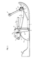
- Fig.1 die Bindung in der Offenstellung ohne Fuß und
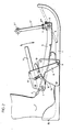
- Fig.2 die Bindung in der am Fuß geschlossenen Stellung, jeweils in Seitenansicht.
- Fig.1 the binding in the open position without foot and
- 2 shows the binding in the closed position at the foot, each in a side view.
In der Zeichnung ist die Bindung mit einer am Wassergleitschuh befestigbaren Grundplatte 1 gezeigt. Ein höhenverstellbarer Niederhalter hat einen (nur in Fig.2 sichtbaren ) quer über den Fußrist legbaren Teil 2, der aus elastisch verformbarem Flachmaterial, z.B. aus Gummi besteht und der Fußform sich anpassend mit seinen Enden nach unten spannbar ist, um den Fuß gegen eine Unterlage zu drücken, die durch die Grundplatte 1 gebildet ist. Der quer über den Rist spannbare Niederhalterteil 2 ist zu diesem Zweck an seinen Enden mittels Klemmleisten, von denen in der Zeichnung nur die deren Fixierung dienenden Schrauben zu sehen sind, an je an einer Seite des Fußes verlaufenden Schenkeln eines U-förmigen Niederhalterbügels 3 befestigt. Der Niederhalterbügel 3 ist um eine Schwenkachse 4 auf- und abschwenkbar, die vor dem Fuß horizontal und quer zur Längsachse der Bindung angeordnet ist.In the drawing, the binding is shown with a base plate 1 attachable to the water slide shoe. A height-adjustable hold-down device has a part 2 (only visible in FIG. 2) which can be placed transversely over the instep and which is made of elastically deformable flat material, e.g. consists of rubber and the shape of the foot can be adjusted with its ends downward in order to press the foot against a base which is formed by the base plate 1. For this purpose, the hold-down part 2 that can be tensioned across the instep is fastened at its ends by means of clamping strips, of which only the screws serving to fix them can be seen in the drawing, to legs of a U-shaped hold-down
Die Schwenkachse 4 kann (bei der in der Zeichnung mit durchbrochenen Linien eingezeichneten Ausführung) entlang einer in der Längsmittelebene der Bindung schräg nach hinten abfallenden Führungsstange 5 verschiebbar festgelegt sein. Der Niederhalterbügel 3 hat zu diesem Zweck vorne eine mittige Bohrung 6, durch welche die Längsführungsstange 5 mit Spiel hindurchgeht. Das Spiel ist notwendig, um das beim Öffnen und Schließen des Niederhalters 2,3 notwendige Schwenken des Niederhalterbügels 3 um die Schwenkachse 4 zu ermöglichen.The
In den Fig.1 und 2 ist im übrigen mit durchlaufenden Linien eine Ausführungsform eingezeichnet, bei der die die Festlegung für die Schwenkachse 4 bildende Längsfuhrungsstange 5 ersetzt ist durch einen Hebearm 5', der um eine oberhalb der Schwenkachse 4 befindliche, ortsfeste Drehachse 5" schwenkbar ist. Beim Öffnen und Schließen des Niederhalters 2,3 - folgt die Schwenkachse 4 bei dieser Variante einer Kreisbahn mit dem Mittelpunkt in der Drehachse 5". Hierbei ist im weiteren zur Anpassung des Niederhalters 2,3 an verschiedene Fußgrößen der Hebelarm 5' längenveränderbar. Er besteht zu diesem Zweck aus zwei getrennten, je mit einem Außengewinde ausgebildeten Abschnitten, die in verschieden gängige Innengewinde eines Schraubenmutterteiles 5"' eingeschraubt sind. Durch Verdrehen des Schraubenmutterteiles 5"' können die Länge des Hebelarmes 5' und die Lage der Kreisbahn der Schwenkachse 4 verändert werden. Die die Längsführungsstange 5 ersetzenden Bauteile sind bei der zuletzt beschriebenen Variante in den Fig.1 und 2 mit 5, jedoch ergänzt durch ein oder mehrere Striche, bezeichnet.1 and 2, an embodiment is shown with continuous lines, in which the
Die Schenkel des U-förmigen Niederhalterbügels 3, der sich mit seinem vorderen Abschnitt etwa in der Ebene der Grundplatte 1 befindet, sind hinten bei 7(Anlenkbolzen) je an einem Ende eines seitlich des Fußes verlaufenden Schräglenkers 8 angelenkt. Das andere (untere) Ende des Schräglenkers 8 ist bei 9 etwa in der Ebene der Grundplatte 1 angelenkt.The legs of the U-shaped hold-down
An einem der Schräglenker 8 ist (bei 10) eine Sperrklinke 11 angelenkt, die durch eine Feder 12 in Eingriff in eine an der Grundplatte 1 fixierte Verzahnung 13 gespannt ist.On one of the
In einer Ebene etwa senkrecht zu der durch die beiden Schräglenker 8 verlaufenden Ebene ist ein U-förmiger Betätigungsbügel 14 angeordnet, der mit den Enden seiner Schenkel an den beiden Schräglenkern 8 befestigt ist. Fig.1 zeigt den Betätigungsbügel 14 in dessen nach vorne gedrückter Lage, wobei die Schräglenker 8 sich in einer aufrechten Stellung befinden und der Niederhalter 2,3 die Offenstellung einnimmt. In dieser Offenstellung befindet sich der Niederhalterbügel 3 mit seiner Schwenkachse 4 am weitesten vorne und mit seinen an den Schräglenkern 8 befestigten Enden in der höchstmöglichen Position. In der Offenstellung kann der Schiläufer mit seinem Fuß unter den Niederhalter 2,3 hineinschlüpfen bzw. von dort herausschlüpfen.In a plane approximately perpendicular to the plane running through the two trailing
Fig.2 zeigt den Betätigungsbügel 14 in dessen nach hinten gezogener Lage, wobei die Schräglenker 8 um die Achse 9 nach hinten geschwenkt sind und der Niederhalter 2,3 die Schließstellung einnimmt. In dieser Schließstellung befindet sich der Niederhalter 2,3 mit seiner Schwenkachse 4 am weitesten hinten und mit seinen an den Schräglenkern 8 befestigten Enden so weit unten, wie dies der über den Fußrist gespannte Niederhalterteil 2 zuläßt.2 shows the actuating
Der Betätigungsbügel 14 ist. um ein geringes Schwenkspiel gegenüber den Schräglenkern 8 schwenkbeweglich, welches Schwenkspiel begrenzt ist einerseits durch die Sperrklinke 11 und andererseits durch den Anlenkbolzen 7, welcher Schräglenker 8 und Niederhalterbügel 3 verbindet. Bei der Schwenkbewegung des Betätigungsbügels 14 in der Öffnungsrichtung gemeinsam mit den Schräglenkern 8 drückt der Betätigungsbügel 14 (wie insbesondere Fig.1 zeigt) die Sperrklinke 11 aus der Verzahnung 13.The
Ein feststehendes Fersenmuldenteil 15, welches an der Grundplatte 11 angeformt ist, bietet dem Fuß ein Widerlager gegen den geschlossenen Niederhalter 2,3.A fixed
Claims (8)
Applications Claiming Priority (2)
| Application Number | Priority Date | Filing Date | Title |
|---|---|---|---|
| AT0313883A AT383962B (en) | 1983-09-01 | 1983-09-01 | BINDING FOR WATER GLIDERS |
| AT3138/83 | 1983-09-01 |
Publications (2)
| Publication Number | Publication Date |
|---|---|
| EP0144537A2 true EP0144537A2 (en) | 1985-06-19 |
| EP0144537A3 EP0144537A3 (en) | 1986-02-26 |
Family
ID=3545896
Family Applications (1)
| Application Number | Title | Priority Date | Filing Date |
|---|---|---|---|
| EP84109889A Withdrawn EP0144537A3 (en) | 1983-09-01 | 1984-08-20 | Waterski binding |
Country Status (3)
| Country | Link |
|---|---|
| US (1) | US4624646A (en) |
| EP (1) | EP0144537A3 (en) |
| AT (1) | AT383962B (en) |
Families Citing this family (12)
| Publication number | Priority date | Publication date | Assignee | Title |
|---|---|---|---|---|
| AU672590B2 (en) * | 1991-12-31 | 1996-10-10 | Michael Forsyth | Collapsible foot retainer |
| US5194023A (en) * | 1992-01-24 | 1993-03-16 | Edward Stone | Individual propelled water craft |
| US5722867A (en) * | 1995-10-23 | 1998-03-03 | Lagrow; Michael C. | Reinforced shoe device |
| US6293577B1 (en) | 1996-10-03 | 2001-09-25 | Peter Shields | Foot binding assembly |
| US6648365B1 (en) | 1997-01-08 | 2003-11-18 | The Burton Corporation | Snowboard binding |
| US6855024B2 (en) * | 2002-04-29 | 2005-02-15 | Walter G. Rothschild | Skis to walk on water |
| US8845372B2 (en) | 2011-03-23 | 2014-09-30 | Jerome Connelly Farmer | Standing watercraft with torso-mounted paddles |
| US9126097B2 (en) * | 2013-02-12 | 2015-09-08 | Jakob Diego Llanes Fettig | Snowboard accessory |
| US9272761B2 (en) | 2013-08-27 | 2016-03-01 | Jerome C. Farmer | Angular velocity-controlled pontoon propulsion system |
| US9675867B2 (en) | 2015-07-28 | 2017-06-13 | X-Sports | Ski binding equipment |
| DE102019127483A1 (en) * | 2019-10-11 | 2021-04-15 | Dalion Watersports UG (haftungsbeschränkt) | binding |
| US11932358B2 (en) * | 2021-03-26 | 2024-03-19 | Chung Kim | Flotation system and shoes thereof |
Citations (2)
| Publication number | Priority date | Publication date | Assignee | Title |
|---|---|---|---|---|
| US2165547A (en) * | 1936-12-16 | 1939-07-11 | Cortlandt T Hill | Foot attachment for skis and the like |
| US2540576A (en) * | 1949-05-03 | 1951-02-06 | William V Goodhue | Water ski binding |
Family Cites Families (5)
| Publication number | Priority date | Publication date | Assignee | Title |
|---|---|---|---|---|
| DE288149C (en) * | 1913-03-27 | |||
| US2382149A (en) * | 1944-02-21 | 1945-08-14 | John M Hartman | Heel support for water skis |
| US3143750A (en) * | 1963-04-22 | 1964-08-11 | Anthony M Kluge | Binding for water skis |
| US3360812A (en) * | 1966-06-09 | 1968-01-02 | Anthony M. Kluge | Binding for water skis |
| US3508288A (en) * | 1968-04-29 | 1970-04-28 | Arlie F Lockwood | Releasable water ski boot structure |
-
1983
- 1983-09-01 AT AT0313883A patent/AT383962B/en not_active IP Right Cessation
-
1984
- 1984-08-20 EP EP84109889A patent/EP0144537A3/en not_active Withdrawn
- 1984-08-22 US US06/643,115 patent/US4624646A/en not_active Expired - Fee Related
Patent Citations (2)
| Publication number | Priority date | Publication date | Assignee | Title |
|---|---|---|---|---|
| US2165547A (en) * | 1936-12-16 | 1939-07-11 | Cortlandt T Hill | Foot attachment for skis and the like |
| US2540576A (en) * | 1949-05-03 | 1951-02-06 | William V Goodhue | Water ski binding |
Also Published As
| Publication number | Publication date |
|---|---|
| US4624646A (en) | 1986-11-25 |
| AT383962B (en) | 1987-09-10 |
| ATA313883A (en) | 1987-02-15 |
| EP0144537A3 (en) | 1986-02-26 |
Similar Documents
| Publication | Publication Date | Title |
|---|---|---|
| DE2800187A1 (en) | SKI AND ICE SKATING BOOTS | |
| CH577282A5 (en) | Ski boot with hinged rear ankle support - has simple fastening and tightening mechanism with interconnected tension members | |
| EP0144537A2 (en) | Waterski binding | |
| DE4106401A1 (en) | Snow-board with step-in binding - has two swivel bars and step element associated with retaining rail | |
| CH679110A5 (en) | ||
| DE60013364T2 (en) | Fastening device for a snow sports equipment | |
| DE1578752B2 (en) | HEEL SECURITY HOLDER FOR A SKI BINDING | |
| DE4424737C1 (en) | Snow=board binding with boot drivers | |
| DE2806937C2 (en) | Optional release ski binding that can be changed for descent and for tours | |
| EP0784943B1 (en) | Skishoe | |
| CH616344A5 (en) | ||
| DE1428991B2 (en) | Sole support device for a safety ski binding that supports the shoe at the tip and heel | |
| DE2456326A1 (en) | Ski safety catch with pivoted attachment - holds shoe sole and is simple to fasten | |
| AT405372B (en) | SNOWBOARD BINDING | |
| DE3529040A1 (en) | Ladder foot | |
| DE2906520A1 (en) | Long distance ski binding - has sole plate connected to rigidly fixed holding plate by spring tensioned swivel system which includes vertical locking pins | |
| DE2636717C3 (en) | A ski brake built into a heel hold-down for releasing ski bindings for a ski that has been detached from the ski boot | |
| DE3702094A1 (en) | Holding device for a shoe on an alpine surfing device | |
| CH679264A5 (en) | ||
| DE608273C (en) | Ski binding with heel tensioner moved to the front of the toe | |
| DE2523927A1 (en) | Automatic brake unit for ski - incorporates hingeable flap behind rear ski edge connected via traction cable to skier | |
| DE1578752C3 (en) | Heel safety holder for a ski binding | |
| DE2304466C3 (en) | Ski binding | |
| DE602004001815T2 (en) | Sports shoe, especially ski boot | |
| DE1951430B2 (en) | Trigger ski binding |
Legal Events
| Date | Code | Title | Description |
|---|---|---|---|
| PUAI | Public reference made under article 153(3) epc to a published international application that has entered the european phase |
Free format text: ORIGINAL CODE: 0009012 |
|
| AK | Designated contracting states |
Designated state(s): AT CH DE FR GB IT LI NL SE |
|
| PUAL | Search report despatched |
Free format text: ORIGINAL CODE: 0009013 |
|
| AK | Designated contracting states |
Designated state(s): AT CH DE FR GB IT LI NL SE |
|
| 17P | Request for examination filed |
Effective date: 19860802 |
|
| 17Q | First examination report despatched |
Effective date: 19870422 |
|
| R17C | First examination report despatched (corrected) |
Effective date: 19870430 |
|
| STAA | Information on the status of an ep patent application or granted ep patent |
Free format text: STATUS: THE APPLICATION IS DEEMED TO BE WITHDRAWN |
|
| 18D | Application deemed to be withdrawn |
Effective date: 19880608 |