EP0144392B1 - Vibrating plate - Google Patents
Vibrating plate Download PDFInfo
- Publication number
- EP0144392B1 EP0144392B1 EP84902240A EP84902240A EP0144392B1 EP 0144392 B1 EP0144392 B1 EP 0144392B1 EP 84902240 A EP84902240 A EP 84902240A EP 84902240 A EP84902240 A EP 84902240A EP 0144392 B1 EP0144392 B1 EP 0144392B1
- Authority
- EP
- European Patent Office
- Prior art keywords
- cross
- vibrating plate
- spring
- handle
- shaft member
- Prior art date
- Legal status (The legal status is an assumption and is not a legal conclusion. Google has not performed a legal analysis and makes no representation as to the accuracy of the status listed.)
- Expired
Links
- 230000033001 locomotion Effects 0.000 claims abstract description 16
- 229920001971 elastomer Polymers 0.000 claims description 26
- 239000000806 elastomer Substances 0.000 claims description 21
- 238000013016 damping Methods 0.000 claims description 6
- 239000011521 glass Substances 0.000 claims description 6
- 239000000463 material Substances 0.000 claims description 5
- 238000009413 insulation Methods 0.000 description 8
- 230000002452 interceptive effect Effects 0.000 description 7
- 239000002184 metal Substances 0.000 description 7
- 230000005540 biological transmission Effects 0.000 description 4
- 239000000725 suspension Substances 0.000 description 3
- 239000004033 plastic Substances 0.000 description 2
- 229920003023 plastic Polymers 0.000 description 2
- 208000019462 Occupational injury Diseases 0.000 description 1
- 229910000831 Steel Inorganic materials 0.000 description 1
- 230000006978 adaptation Effects 0.000 description 1
- 230000003321 amplification Effects 0.000 description 1
- 239000010426 asphalt Substances 0.000 description 1
- 238000000576 coating method Methods 0.000 description 1
- 238000005056 compaction Methods 0.000 description 1
- 238000003199 nucleic acid amplification method Methods 0.000 description 1
- 230000010355 oscillation Effects 0.000 description 1
- 239000011148 porous material Substances 0.000 description 1
- 239000012858 resilient material Substances 0.000 description 1
- 239000004576 sand Substances 0.000 description 1
- 239000010959 steel Substances 0.000 description 1
- 238000004073 vulcanization Methods 0.000 description 1
Images


Classifications
-
- F—MECHANICAL ENGINEERING; LIGHTING; HEATING; WEAPONS; BLASTING
- F16—ENGINEERING ELEMENTS AND UNITS; GENERAL MEASURES FOR PRODUCING AND MAINTAINING EFFECTIVE FUNCTIONING OF MACHINES OR INSTALLATIONS; THERMAL INSULATION IN GENERAL
- F16F—SPRINGS; SHOCK-ABSORBERS; MEANS FOR DAMPING VIBRATION
- F16F15/00—Suppression of vibrations in systems; Means or arrangements for avoiding or reducing out-of-balance forces, e.g. due to motion
- F16F15/02—Suppression of vibrations of non-rotating, e.g. reciprocating systems; Suppression of vibrations of rotating systems by use of members not moving with the rotating systems
- F16F15/04—Suppression of vibrations of non-rotating, e.g. reciprocating systems; Suppression of vibrations of rotating systems by use of members not moving with the rotating systems using elastic means
- F16F15/08—Suppression of vibrations of non-rotating, e.g. reciprocating systems; Suppression of vibrations of rotating systems by use of members not moving with the rotating systems using elastic means with rubber springs ; with springs made of rubber and metal
-
- B—PERFORMING OPERATIONS; TRANSPORTING
- B25—HAND TOOLS; PORTABLE POWER-DRIVEN TOOLS; MANIPULATORS
- B25D—PERCUSSIVE TOOLS
- B25D17/00—Details of, or accessories for, portable power-driven percussive tools
- B25D17/04—Handles; Handle mountings
- B25D17/043—Handles resiliently mounted relative to the hammer housing
Definitions
- This invention relates to a so-called vibrating plate, that is a device which comprises a compactor plate with engine and vibration generator, said compactor plate being adapted for application to the ground.
- Such vibrating plates can be used for compaction of sand and gravel as well as asphalt coatings.
- Such vibrating plates have a handle by which the vibrating plate is operated, the handle comprising a lingitudinally extending shaft member and a transversely extending cross-member carried by the shaft member.
- a difficult problem associated with this type of tool resides in the transmission of vibrations from the vibrating plate to the operator. Therefore, one has tried in different ways to dampen the transmission of vibrations.
- the arangement also includes a device for restricting the spring deflection upon extertion of a force over a predetermined level.
- This invention aims at providing a vibrating plate in which the cross-member and shaft member of the handle are interconnected by at least one spring element the stiffness of which has been adapted to the mass of the cross-member such that an excellent vibration insulation is obtained.
- the invention also aims at providing a vibrating plate the cross-member of which is highly insulated from the remaining vibrating plate by means of a simple but effective vibration insulation device.
- a vibrating plate of the type defined in the preamble of claim 1 shall be characterised in that the mass of the cross-member and the spring stiffness of the spring element or elements are so adapted to one another and to the vibrating frequency of the vibrating plate that the relationship between the frequency of the vibration generator and the characteristic frequency of the cross-member with regard to translational and rotational movements respectively along and about the axis of the operating member and respectively along and about two directions at right angles to said axis and also to one another, is > /2.
- the invention is based on the observation that one has to adapt the spring stiffness and the mass of the cross-member in such a way to one another that the characteristic frequencies of the cross-member (with regard to said directions) lie substantially below the interfering frequency, i.e. the interfering frequency generated by the vibrating plate. Only in this way is it thus possible to safeguard a highgrade vibration insulation and prevent an amplification of the transmission of vibrations as a result of natural oscillation conditions in the cross-member.
- the cross-member is connected at both of its ends to the shaft member of the handle and if each of the spring elements is in the form of an elastomer body which is of approximately hour-glass shape and which is axially arranged in relation to the cross-member.
- the spring deflection restricting mechanical device is formed by a cup-shaped means which is connected to the shaft member of the handle and has a larger inner diameter than the outer diameter of the part of the cross-member projecting into said cup-shaped means. It is particularly advantageous if the part projecting into the cupshaped means is provided with a preferably annular, shock-absorbing and shock-damping elastomer element adapted to engage said cup-shaped means.
- the cross-member preferably has a jacket of resilient elastomer material.
- the vibrating plate according to the present invention is diagrammatically shown in Fig. 5 and comprises a compactor plate 50 which is adapted for application to the ground and which supports an engine 51 with a vibrating device (not shown in detail). Besides the vibrating plate has a handle 52 which comprises a shaft member 53 and an cross-member 54.
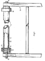
- Fig. 1 shows an example how the handle for the vibrating plate according to the invention may be designed.
- the handle thus has a shaft member 10 which corresponds to the shaft member 53 in Fig. 5.
- An cross-member 11 is connected to said shaft member.
- the cross-member 11 has a core 12 of metal or plastics, preferably a steel rod, about which a jacket 13 of a suitable resilient material, preferably elastomer material, is fastened.
- the elastomer material most preferably is porous with closed pores.
- the cross-member 11 has a cup-shaped means 14 the open side of which is facing outwardly, A ring 15 of rubber or plastics is fixed about the periphery of the cupshaped means 14, for instance by vulcanization.
- a rubber spring 16 of hour-glass shape is fixed centrally in the cup-shaped means 14, for instance with the aid of a metal plate which is vulcanized to the elastomer spring and faces the cross-member 11.
- a metal plate is also vulcanized to the other ehd of the elastomer spring 16, said metal plate being connected to or integral with a bolt 17.
- a second cup-shaped means 19 is arranged on the bolt 17 and the open side of said means faces the cross-member 11.
- the cup- shaped means 19 has a larger diameter than the cup-shaped means 14 and the rubber ring 15 fixed thereto, and extends inwardly over said ring.
- the cross-member 11 is fixed between the upstanding shaft members 10 of the handle by means of the bolts 17 passed through transverse bores at the outer ends of the shaft member and anchored to the shaft members by means of nuts.
- the cup-shaped means 19 are passed over the bolts 17 and clamped between the corresponding elastomer spring and the adjacent shaft member 10.
- Fig. 3 shows a further example how the handle of the vibrating plate may be designed.
- the handle comprises an angle piece 20 one end of which is passed over the shaft member 10 of the handle and anchored thereto by means of two fastening screws 21 with cap nuts 22.
- the outer end of the angle piece is integral with the cup-shaped means 19 into which the cross-member 11 of the handle projects.
- This embodiment of the handle and its cross-member 11 differs from the embodiment shown in Fig. 1 also with regard to the connection of the elastomer spring 16 with the cross-member 11 and the angle piece 20.
- the elastomer spring 16 is in the shape of an hour-glass or dumbbell and has metal plates vulcanized to its end surfaces.
- the right-hand metal plate shown in the drawing is connected to the fastening bolt 17 which penetrates through a hole of the angle piece 20 and is clamped thereto by means of the nut 18.
- the metal plate vulcanized to the other end of the elastomer spring 16 is integral or united with a cylindrical pin 23 which projects into a cylindrical bore 24 in the end surface of the core 12 of the cross-member.
- the core 12 with its jacket 13 is thus rotatable in relation to the elastomer spring 16.
- the embodiment according to Fig. 3 differs from that of Fig. 1 also with regard to the cup-shaped means 14 which in this case is facing in the opposite direction and thus grasps the core 12 and is connected thereto.
- an annular rubber body 15 is fastened to the outer side of the cup-shaped means 14 in order to serve as a spring deflection restricting device together with the cup-shaped means 19 on the angle piece 20.
- Fig. 4 there is shown a further example how the vibrating plate according to the invention may be provided with a handle for vibration insulation.
- the handle is mounted with the aid of special brackets 30 which are mounted on the handle 10 of the vibrating plate by means of bolts 31 and a clasp 32.
- the cup-shaped means 14 in this case is vulcanized in one piece with the elastomer spring 16 and provided with the elastomer ring 15 on its outer side.
- one shall in accordance with the present invention adapt the mass of the cross-member and the spring stiffness of the spring element or elements in a certain way to each other and to the frequency of the vibrating plate, i.e. the interfering frequency.
- This adaptation shall take place such that the relationship between the interfering frequency and the characteristic frequency of the cross-member with regard to translational and rotational movements respectively along and about the axis of the cross-member and respectively along and about two directions at right angles to said axis and also to each other, is > /2.
- the theoretical calculation of the correct spring stiffness and mass for the vibration insulating handle of the vibrating plate shall be described hereinbelow with reference to Fig.
- FIG. 2 which diagrammatically shows the shaft members 10 of the handle and the cross-member 11 mounted therebetween with the aid of the springs 16.
- Fig. 2 there are shown three coordinates at right angles to each other, namely the Y-direction which is axial with the cross-member 11, and the two directions Z and X which are at right angles to each other and to the Y-direction.
- the axis X is at right angles to the paper and extends through the point of intersection of the two arrows Y and Z.
- the suspension of the cross-member 11 is such that for the calculation of the vibration insulation one has to consider six different vibration directions to permit establishing the exact position of the cross-member in each particular case.
- Three of these movements are translation movements, namely in the direction of the axes X, Y and Z.
- rotational movements about each of these axes a designates rotation about the X-axis, rotation about the Y-axis and y rotation about the Z-axis.
- a characteristic frequency which is important in conjunction with the present invention.
Landscapes
- Engineering & Computer Science (AREA)
- Mechanical Engineering (AREA)
- General Engineering & Computer Science (AREA)
- Chemical & Material Sciences (AREA)
- Combustion & Propulsion (AREA)
- Physics & Mathematics (AREA)
- Acoustics & Sound (AREA)
- Aviation & Aerospace Engineering (AREA)
- Vibration Prevention Devices (AREA)
- Road Paving Machines (AREA)
- Apparatuses For Generation Of Mechanical Vibrations (AREA)
- Electrical Discharge Machining, Electrochemical Machining, And Combined Machining (AREA)
Applications Claiming Priority (6)
| Application Number | Priority Date | Filing Date | Title |
|---|---|---|---|
| SE8303080 | 1983-06-01 | ||
| SE8303080A SE436918B (sv) | 1983-06-01 | 1983-06-01 | Anordning vid handtag for vibrerande maskiner |
| SE8306440A SE8306440L (sv) | 1983-06-01 | 1983-11-22 | Vibratorplatta |
| SE8306439A SE8306439L (sv) | 1983-06-01 | 1983-11-22 | Anordning vid handtag for vibrerande maskiner |
| SE8306440 | 1983-11-22 | ||
| SE8306439 | 1983-11-22 |
Publications (2)
| Publication Number | Publication Date |
|---|---|
| EP0144392A1 EP0144392A1 (en) | 1985-06-19 |
| EP0144392B1 true EP0144392B1 (en) | 1986-12-17 |
Family
ID=27355293
Family Applications (2)
| Application Number | Title | Priority Date | Filing Date |
|---|---|---|---|
| EP84902240A Expired EP0144392B1 (en) | 1983-06-01 | 1984-05-30 | Vibrating plate |
| EP84850166A Withdrawn EP0128128A3 (en) | 1983-06-01 | 1984-05-30 | A handle arrangement for vibrating machines |
Family Applications After (1)
| Application Number | Title | Priority Date | Filing Date |
|---|---|---|---|
| EP84850166A Withdrawn EP0128128A3 (en) | 1983-06-01 | 1984-05-30 | A handle arrangement for vibrating machines |
Country Status (7)
| Country | Link |
|---|---|
| US (1) | US4609055A (da) |
| EP (2) | EP0144392B1 (da) |
| DE (1) | DE3461730D1 (da) |
| DK (1) | DK267784A (da) |
| IT (1) | IT1196125B (da) |
| NO (1) | NO842127L (da) |
| WO (1) | WO1984004791A1 (da) |
Families Citing this family (21)
| Publication number | Priority date | Publication date | Assignee | Title |
|---|---|---|---|---|
| DE3503938A1 (de) * | 1985-02-06 | 1986-08-07 | Fraunhofer-Gesellschaft zur Förderung der angewandten Forschung e.V., 8000 München | Elastische griffholmen-lagerung fuer beidhaendig gefuehrte motorgeraete |
| FR2673588B1 (fr) * | 1991-03-07 | 1993-05-28 | Staub Ind Sa | Dispositif antivibratoire pour guidon de motoculteur. |
| EP0703320A3 (de) * | 1994-09-19 | 1996-10-16 | Diehl Remscheid Gmbh & Co | Führungsrahmen mit Handführung für Verdichter |
| US6327940B1 (en) * | 2000-02-16 | 2001-12-11 | National-Oilwell, L.P. | Multi-piece manual tong safety handle |
| CA2353510A1 (en) * | 2001-07-16 | 2003-01-16 | Katch Kan Holdings Ltd. | Hand guard for drilling rig hand tongs |
| US6749365B2 (en) * | 2002-03-18 | 2004-06-15 | M-B-W Inc. | Vibration isolation for a percussion rammer |
| CA2423282A1 (fr) * | 2003-03-19 | 2004-09-19 | Universite De Sherbrooke | Poignee anti-vibratile pour outils percutants ou a mouvement alternatif |
| GB2402098B (en) * | 2003-05-21 | 2007-10-17 | Black & Decker Inc | Vibration reduction apparatus for power tool and power tool incorporating such apparatus |
| USD517095S1 (en) * | 2004-01-23 | 2006-03-14 | Belle Engineering (Sheen) Limited | Compactor handle |
| US7039986B2 (en) * | 2004-02-05 | 2006-05-09 | Multiquip, Inc. | Vibration isolation machine handle |
| US20060207063A1 (en) * | 2005-03-01 | 2006-09-21 | Multiquip. Inc. | Vibration dampening handle |
| DE102005033596A1 (de) * | 2005-07-19 | 2007-02-01 | Sabo - Maschinenfabrik Gmbh | Gerät vorzugsweise zur Rasen-, Garten- bzw. Grundstückspflege, Dämpfungseinrichtung und Dämpfungselement |
| US7878490B2 (en) | 2005-07-19 | 2011-02-01 | Deere & Company | Damping arrangement for lawn and garden care implement |
| US7411388B2 (en) * | 2005-08-30 | 2008-08-12 | Baker Hughes Incorporated | Rotary position sensor and method for determining a position of a rotating body |
| US7530407B2 (en) * | 2005-08-30 | 2009-05-12 | Baker Hughes Incorporated | Rotary coring device and method for acquiring a sidewall core from an earth formation |
| DE102005046432A1 (de) * | 2005-09-28 | 2007-03-29 | Robert Bosch Gmbh | Elektrowerkzeugmaschine sowie Vibrationsdämfpungsvorrichtung |
| CA493745A (en) * | 2006-10-04 | 1953-06-16 | E. Glassburn William | Bridge-connected relay |
| US20080289842A1 (en) * | 2007-05-24 | 2008-11-27 | Larry Jake Chapple | Walk behind power tool vibration control handle |
| WO2011041417A2 (en) * | 2009-09-29 | 2011-04-07 | Kineticane, Llc | Walking cane |
| US20240426066A1 (en) * | 2023-06-23 | 2024-12-26 | Milwaukee Electric Tool Corporation | Construction tool handle |
| CN116856340B (zh) * | 2023-09-05 | 2023-11-17 | 山东省水利科学研究院 | 一种水利工程护坡装置 |
Family Cites Families (10)
| Publication number | Priority date | Publication date | Assignee | Title |
|---|---|---|---|---|
| DE700854C (de) * | 1936-02-23 | 1941-01-02 | Robert Wacker Fa | Handgriffanordnung an Geraeten mit schwingenden und schlagenden Kraeften |
| US2831463A (en) * | 1955-07-07 | 1958-04-22 | Atlas Copco Ab | Cushioning device for hammer tools |
| CH348387A (de) * | 1956-06-28 | 1960-08-31 | A Voigt Clemens | Einrichtung zur gummielastischen Lagerung eines Antriebsaggregates mit schnellrotierendem Teil, insbesondere für Wäscheschleudern |
| US3158256A (en) * | 1961-02-15 | 1964-11-24 | Eriez Mfg Co | Feeder and spring with inherent damping |
| US3232188A (en) * | 1961-09-18 | 1966-02-01 | Dyna Quip Inc | Tamping machine |
| US3275089A (en) * | 1963-11-05 | 1966-09-27 | Westinghouse Air Brake Co | Handle means for percussive tool |
| JPS5834271B2 (ja) * | 1980-07-18 | 1983-07-26 | 日立工機株式会社 | 振動工具のハンドル防振装置 |
| US4420989A (en) * | 1981-07-06 | 1983-12-20 | Finkle Louis J | Adjustable shock absorbing handlebar structure |
| DE3173110D1 (en) * | 1981-07-09 | 1986-01-16 | Toyota Motor Co Ltd | A cushioned mounting device |
| EP0081079B1 (en) * | 1981-12-09 | 1986-03-12 | Sunnex Aktiebolag | Arrangement for damping the transmission of vibrations |
-
1984
- 1984-05-29 NO NO842127A patent/NO842127L/no unknown
- 1984-05-30 EP EP84902240A patent/EP0144392B1/en not_active Expired
- 1984-05-30 DK DK267784A patent/DK267784A/da unknown
- 1984-05-30 DE DE8484902240T patent/DE3461730D1/de not_active Expired
- 1984-05-30 EP EP84850166A patent/EP0128128A3/en not_active Withdrawn
- 1984-05-30 WO PCT/SE1984/000205 patent/WO1984004791A1/en not_active Ceased
- 1984-05-30 US US06/681,991 patent/US4609055A/en not_active Expired - Fee Related
- 1984-05-31 IT IT21187/84A patent/IT1196125B/it active
Also Published As
| Publication number | Publication date |
|---|---|
| IT8421187A0 (it) | 1984-05-31 |
| IT1196125B (it) | 1988-11-10 |
| EP0144392A1 (en) | 1985-06-19 |
| EP0128128A2 (en) | 1984-12-12 |
| DK267784D0 (da) | 1984-05-30 |
| DK267784A (da) | 1984-12-02 |
| DE3461730D1 (en) | 1987-01-29 |
| IT8421187A1 (it) | 1985-12-01 |
| NO842127L (no) | 1984-12-03 |
| EP0128128A3 (en) | 1986-12-30 |
| US4609055A (en) | 1986-09-02 |
| WO1984004791A1 (en) | 1984-12-06 |
Similar Documents
| Publication | Publication Date | Title |
|---|---|---|
| EP0144392B1 (en) | Vibrating plate | |
| US6749365B2 (en) | Vibration isolation for a percussion rammer | |
| US4800965A (en) | Damping element, and its installation in a motor-driven hand tool | |
| KR0162677B1 (ko) | 방진 지지체 | |
| CA1221991A (en) | Vibration damper | |
| US5769174A (en) | Parallel displacement single axis vibration isolator | |
| EP0131795B1 (en) | Improved insulator for use in automotive suspension or the like | |
| SU1194288A3 (ru) | Вибромолот | |
| JPH11218186A (ja) | 振動装置用改良しゃ断装置 | |
| US4641732A (en) | Damping structure | |
| EP0457740A1 (en) | A vibrator damped hand held rotary grinding machine | |
| EP0547469A1 (de) | Aktives, elastisches Lager | |
| US3275089A (en) | Handle means for percussive tool | |
| US20030019704A1 (en) | Dynamic damping device for steering system | |
| GB2138348A (en) | Vibration damping handgrip | |
| US5031273A (en) | Vibration-free handle | |
| AU679144B2 (en) | Structureborne noise isolator | |
| EP2011920B1 (en) | Speed controlled eccentric assembly | |
| Andersson | Design and testing of a vibration attenuating handle | |
| JPH0324539B2 (da) | ||
| EP0081079B1 (en) | Arrangement for damping the transmission of vibrations | |
| SU1421908A1 (ru) | Виброизолирующа опора | |
| JP3738370B2 (ja) | ロボット用防振装置 | |
| RU2655687C1 (ru) | Виброизолированный фундамент с пневматической системой виброизоляции | |
| RU2658936C1 (ru) | Резиновый виброизолятор арочного типа |
Legal Events
| Date | Code | Title | Description |
|---|---|---|---|
| PUAI | Public reference made under article 153(3) epc to a published international application that has entered the european phase |
Free format text: ORIGINAL CODE: 0009012 |
|
| 17P | Request for examination filed |
Effective date: 19841115 |
|
| AK | Designated contracting states |
Designated state(s): DE FR GB SE |
|
| 17Q | First examination report despatched |
Effective date: 19860224 |
|
| RAP1 | Party data changed (applicant data changed or rights of an application transferred) |
Owner name: DYNAPAC AKTIEBOLAG |
|
| GRAA | (expected) grant |
Free format text: ORIGINAL CODE: 0009210 |
|
| AK | Designated contracting states |
Kind code of ref document: B1 Designated state(s): DE FR GB SE |
|
| REF | Corresponds to: |
Ref document number: 3461730 Country of ref document: DE Date of ref document: 19870129 |
|
| ET | Fr: translation filed | ||
| PLBE | No opposition filed within time limit |
Free format text: ORIGINAL CODE: 0009261 |
|
| STAA | Information on the status of an ep patent application or granted ep patent |
Free format text: STATUS: NO OPPOSITION FILED WITHIN TIME LIMIT |
|
| 26N | No opposition filed | ||
| REG | Reference to a national code |
Ref country code: GB Ref legal event code: 732 |
|
| REG | Reference to a national code |
Ref country code: FR Ref legal event code: TP |
|
| PGFP | Annual fee paid to national office [announced via postgrant information from national office to epo] |
Ref country code: GB Payment date: 19910520 Year of fee payment: 8 |
|
| PGFP | Annual fee paid to national office [announced via postgrant information from national office to epo] |
Ref country code: SE Payment date: 19910521 Year of fee payment: 8 |
|
| PGFP | Annual fee paid to national office [announced via postgrant information from national office to epo] |
Ref country code: FR Payment date: 19910522 Year of fee payment: 8 |
|
| PGFP | Annual fee paid to national office [announced via postgrant information from national office to epo] |
Ref country code: DE Payment date: 19910628 Year of fee payment: 8 |
|
| PG25 | Lapsed in a contracting state [announced via postgrant information from national office to epo] |
Ref country code: GB Effective date: 19920530 |
|
| PG25 | Lapsed in a contracting state [announced via postgrant information from national office to epo] |
Ref country code: SE Effective date: 19920531 |
|
| GBPC | Gb: european patent ceased through non-payment of renewal fee |
Effective date: 19920530 |
|
| PG25 | Lapsed in a contracting state [announced via postgrant information from national office to epo] |
Ref country code: FR Effective date: 19930129 |
|
| PG25 | Lapsed in a contracting state [announced via postgrant information from national office to epo] |
Ref country code: DE Effective date: 19930202 |
|
| REG | Reference to a national code |
Ref country code: FR Ref legal event code: ST |
|
| EUG | Se: european patent has lapsed |
Ref document number: 84902240.5 Effective date: 19921204 |