EP0144145B2 - Pistons - Google Patents
Pistons Download PDFInfo
- Publication number
- EP0144145B2 EP0144145B2 EP84307372A EP84307372A EP0144145B2 EP 0144145 B2 EP0144145 B2 EP 0144145B2 EP 84307372 A EP84307372 A EP 84307372A EP 84307372 A EP84307372 A EP 84307372A EP 0144145 B2 EP0144145 B2 EP 0144145B2
- Authority
- EP
- European Patent Office
- Prior art keywords
- piston
- pair
- piston ring
- bores
- gudgeon pin
- Prior art date
- Legal status (The legal status is an assumption and is not a legal conclusion. Google has not performed a legal analysis and makes no representation as to the accuracy of the status listed.)
- Expired - Lifetime
Links
Images
Classifications
-
- F—MECHANICAL ENGINEERING; LIGHTING; HEATING; WEAPONS; BLASTING
- F02—COMBUSTION ENGINES; HOT-GAS OR COMBUSTION-PRODUCT ENGINE PLANTS
- F02F—CYLINDERS, PISTONS OR CASINGS, FOR COMBUSTION ENGINES; ARRANGEMENTS OF SEALINGS IN COMBUSTION ENGINES
- F02F3/00—Pistons
- F02F3/0015—Multi-part pistons
-
- F—MECHANICAL ENGINEERING; LIGHTING; HEATING; WEAPONS; BLASTING
- F16—ENGINEERING ELEMENTS AND UNITS; GENERAL MEASURES FOR PRODUCING AND MAINTAINING EFFECTIVE FUNCTIONING OF MACHINES OR INSTALLATIONS; THERMAL INSULATION IN GENERAL
- F16J—PISTONS; CYLINDERS; SEALINGS
- F16J1/00—Pistons; Trunk pistons; Plungers
- F16J1/10—Connection to driving members
- F16J1/14—Connection to driving members with connecting-rods, i.e. pivotal connections
- F16J1/16—Connection to driving members with connecting-rods, i.e. pivotal connections with gudgeon-pin; Gudgeon-pins
-
- F—MECHANICAL ENGINEERING; LIGHTING; HEATING; WEAPONS; BLASTING
- F02—COMBUSTION ENGINES; HOT-GAS OR COMBUSTION-PRODUCT ENGINE PLANTS
- F02F—CYLINDERS, PISTONS OR CASINGS, FOR COMBUSTION ENGINES; ARRANGEMENTS OF SEALINGS IN COMBUSTION ENGINES
- F02F2200/00—Manufacturing
- F02F2200/04—Forging of engine parts
-
- F—MECHANICAL ENGINEERING; LIGHTING; HEATING; WEAPONS; BLASTING
- F05—INDEXING SCHEMES RELATING TO ENGINES OR PUMPS IN VARIOUS SUBCLASSES OF CLASSES F01-F04
- F05C—INDEXING SCHEME RELATING TO MATERIALS, MATERIAL PROPERTIES OR MATERIAL CHARACTERISTICS FOR MACHINES, ENGINES OR PUMPS OTHER THAN NON-POSITIVE-DISPLACEMENT MACHINES OR ENGINES
- F05C2201/00—Metals
- F05C2201/02—Light metals
- F05C2201/021—Aluminium
-
- F—MECHANICAL ENGINEERING; LIGHTING; HEATING; WEAPONS; BLASTING
- F05—INDEXING SCHEMES RELATING TO ENGINES OR PUMPS IN VARIOUS SUBCLASSES OF CLASSES F01-F04
- F05C—INDEXING SCHEME RELATING TO MATERIALS, MATERIAL PROPERTIES OR MATERIAL CHARACTERISTICS FOR MACHINES, ENGINES OR PUMPS OTHER THAN NON-POSITIVE-DISPLACEMENT MACHINES OR ENGINES
- F05C2201/00—Metals
- F05C2201/04—Heavy metals
- F05C2201/0433—Iron group; Ferrous alloys, e.g. steel
- F05C2201/0448—Steel
-
- F—MECHANICAL ENGINEERING; LIGHTING; HEATING; WEAPONS; BLASTING
- F05—INDEXING SCHEMES RELATING TO ENGINES OR PUMPS IN VARIOUS SUBCLASSES OF CLASSES F01-F04
- F05C—INDEXING SCHEME RELATING TO MATERIALS, MATERIAL PROPERTIES OR MATERIAL CHARACTERISTICS FOR MACHINES, ENGINES OR PUMPS OTHER THAN NON-POSITIVE-DISPLACEMENT MACHINES OR ENGINES
- F05C2251/00—Material properties
- F05C2251/04—Thermal properties
- F05C2251/042—Expansivity
Definitions
- the gudgeon pin bores are very close to the crown end of the piston. This means that the overall axial length of the piston from the crown 20 to the lower edge can be decreased.
- the axial length of the piston may be 50% to 70% of the diameter of the piston.
Description
- The invention relates to pistons for internal combustion engines of the kind comprising a crown, a ring band extending around the crown and including two or more piston ring grooves, and a pair of co-axial gudgeon pin bores which receive a gudgeon pin by which the piston is attached to an associated connecting rod.
- Such a piston also has a skirt which depends from the ring band and which is intersected by the gudgeon pin bores. The lower edge of the skirt defines the lower edge of the piston. In use, the piston reciprocates in an associated cylinder or liner formed in an engine block and, for a given stroke of the piston, the height of the block, and consequently the mass of the block is determined at least in part by the axial length of the piston from the crown to the lower edge; the shorter the axial length, the lower the height of the block.
- US-A-2372993 and GB-A-1155176 show a piston according to the preamble of claim 1. In US-A-2372993, the gudgeon pin bores intersect the skirt beneath the ring band. In GB-A-115176 the skirt is cut away around the gudgeon pin bores and spaced piston ring grooves are provided on the skirt.
- DE-C-708646 shows a piston for an internal combustion engine according to the preamble of claim 3.
- FR-A-2238372 shows a piston in which a first piston part forms an inner portion of the crown, gudgeon pin bores and a lower part of the ring band containing a lowermost piston ring groove. A second piston part forms an outer periphery of the crown and an upper part of the ring band containing two piston ring grooves. A third piston part is sleeve-shaped and forms a skirt having gudgeon pin bores in register with the gudgeon pin bores of the first part. The three piston parts are welded together to form a complete piston.
- DE-A-2504910 discloses a piston primarily for a refrigerant compressor comprising a crown and a skirt extending around the piston to a lower edge. A pair of co-axial gudgeon pin bores intersect the skirt and are for receipt of a gudgeon pin. One piston ring groove is provided adjacent the crown and a second piston ring groove is provided in the skirt and has upper and lower radially extending side walls connected by a base, the upper radially extending side wall being continuous around the skirt and the gudgeon pin bores intersecting the lower radially extending side wall of the second piston ring groove so that a piston ring in said groove is unsupported at the two diametrically opposed portions of the lower side wall where the bores intersect said wall.
- According to a first aspect of the invention, there is provided a piston for an internal combustion engine formed in one piece of the kind comprising a crown, at least two axially spaced piston ring grooves, a lowermost of said at least two axially spaced piston ring grooves having upper and lower axially spaced and radially extending side walls connected by a base, said upper radially extending side wall being continuous around the piston, a skirt extending around the piston beneath the lowermost of said at least two axially spaced piston ring grooves and having a lower edge, and a pair of co-axial bores being provided for receiving a gudgeon pin, said pair of bores intersecting the lower side wall and the base of said lowermost of said at least two piston ring grooves, a piston ring in said lowermost of said pair of piston ring grooves being unsupported at the two diametrically opposed portions of said lower side wall where the bores intersect said lowermost of said pair of piston ring grooves, the at least two piston ring grooves being formed in a ring band surrounding the crown, said pair of bores intersecting the ring band and being located at least substantially equidistandly between the crown and said lower edge.
- According to a second aspect of the invention, there is provided a piston for an internal combustion engine of the kind comprising a separately formed upper piston part including a crown, at least two axially spaced piston ring grooves and a pair of co-axial bores for receiving a gudgeon pin, and a separately formed sleeve-shaped lower piston part connected to said upper piston part and forming a skirt whereby said upper piston part forms an upper portion of a ring band surrounding the crown, the lower piston part providing at least one further piston ring groove characterised in that said at least one further piston ring groove iO spaced axially from a lowermost of said at least two piston ring grooves by substantially the same axial distance as the spacing of said at least two axially spaced piston ring grooves to provide a lower portion of said ring band formed as a continuation of said upper portion of the ring band, said pairs of co-axial bores terminating inwardly of said second piston part so that the ends of said pair of gudgeon pin bores are covered by said sleeve-shaped lower piston part and imaginary extensions thereof at least partially intersecting the ring band through said at least one further piston ring groove to reduce the overall height of the piston.
- The following is a more detailed description of some embodiments of the invention, by way of example, reference being made to the accompanying drawings in which:-
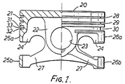
- Figure 1 is a side elevation, partly in section, of a first form of piston for an internal combustion engine,
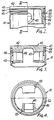
- Figure 2 is a side elevation, partly in section, of a second form of piston for an internal combustion engine, the piston being formed in two parts,
- Figure 3 is a section on the line IV IV of Figure 2, and
- Figure 4 is an underneath plan view of the piston of Figures 2 and 3, the lower half of this view being in section,
- Referring first to Figure 1, in this embodimentthe piston is cast or forged from aluminium or an aluminium alloy; for example it may be made by a squeeze casting process. The piston comprises a
crown 20 surrounded by aring band 21. Agudgeon pin boss 22 defines a pair of co-axialgudgeon pin bores 23 and supports thecrown 20 and ring band 2' onflanges 24. A skirt is formed by two pairs ofarcuate skirt portions upper skirt portions ring band 21 while thelower skirt portions limbs 27 extending from thegudgeon pin boss 22. - The
ring band 21 is provided with threepiston ring grooves side walls base 33. In the case of the two upper piston ring grooves 28, 29 thewalls base 33 are continuous around the whole circumference of the piston. In the case of the lowerpiston ring groove 30, however, thegudgeon pin bores 23 are so arranged that they intersect thelower wall 32 and thebase 33 of thisgroove 30 at diametrically opposed points on the circumference of thering band 21. - The two upper
piston ring grooves lower groove 30 contains an oil I scraper ring (not shown) of any suitable conventional design. Although the oil scraper ring will be unsupported on one side for a part of its circumference, this has not, in general, been found to be a problem. If there is any problem, a clip-on support may be provided which spans the gap to support this part of the ring. In addition, the ring may be positively located to prevent its rotational movement, thus preventing a gap provided in the ring from coinciding with the gap in thelower side wall 32. - The gudgeon pin (not shown) can also be of conventional design since there is no problem with the passage of gases between the gudgeon pin and the gudgeon pin bores 13 due to the two compression rings above the
gudgeon pin bores 23. - Referring next to Figures 2, 3 and 4, the second piston is formed in two parts; an
upper part 40 and alower part 41. These may be forged or cast, particularly squeeze cast, from aluminium or aluminium alloys. The material may be the same for both parts or different. Alternatively, the upper part can be made from a suitable metallic material and the lower part from a suitable plastics material. - The upper part40 defines a
crown 42 and the upper portion of aring band 43 which includes twopiston ring grooves ring band 43. Theupper part 40 also defines twogudgeon pins ring band 43, there is an inwardly directedstep 48 leading to a generallycylindrical surface 49 extending around thegudgeon pin bores 46, 47 (see Figs. 2 and 4). - The
lower part 41 is formed as a sleeve and includes, at the upper end thereof, apiston ring groove 50. Theouter surface 51 of thesleeve 41 forms a skirt for the piston. The inner surface of the sleeve is formed with anannular cavity 52 which forms a heat barrier. - The
sleeve 41 is a sliding fit over the generallycylindrical surface 49 of theupper part 40, so that the top of the sleeve sits in thestep 48 and the outer surface of thering band 43 is contiguous with theouter surface 51 of the sleeve. Thesleeve 41 is connected to theupper part 40 in any convenient way, for example by welding, particularly by friction welding, or by gluing or by shrinking, or by screwing or by the use of releasable mechanical locking means. An example of the latter is a tab washer orscrews 55 as seen in Figure 2. - It will be seen that the
sleeve 41 covers the open ends of thegudgeon pin bores piston ring groove 50 formed on the sleeve, It will be appreciated, however, that thesleeve 41 need not be formed in one piece, it could be formed in two or more pieces. - Where the sleeve is in one piece, the gudgeon pin (not shown) must be pressed through the gudgeon pin bores and the little end of the connecting rod before the
sleeve 41 is fitted over theupper part 40 of the piston. - It will be seen that both the embodiments described above with reference to the drawings, the gudgeon pin bores are very close to the crown end of the piston. This means that the overall axial length of the piston from the
crown 20 to the lower edge can be decreased. For example, the axial length of the piston may be 50% to 70% of the diameter of the piston. - This has the advantage that the compression height (i.e. the distance between the axes of the
gudgeon pin bores 23 and the top of the crown of the piston is minimised, which is a desirable object in piston design. - This has the benefit that, for a given stroke of engine, the height of the engine can be decreased. This will give a smaller engine which decreases the weight of the vehicle and also lowers the bonnet line of the vehicle. This can allow styling improvements to be made and will also increase the drivers forward visibility from the interior of the vehicle. Further, the piston is short and light which decreases its inertia and increases its acceleration so improving the performance of the engine.
- A further advantage of these arrangements is that they allow a gudgeon pin to be used which is of relatively large diameter without increasing he compression height of the piston.
- It will also be seen that the gudgeon pin bore is arranged substantially equidistantly between the crown and the lower edge of the piston in both the embodiments described above with reference to the drawings. This means that the piston is, in use, better balanced, and requires less barrelling of the associated cylinder or liner.
- A particular benefit of the second piston (Figs. 2 to 4) is that it allows the gudgeon pin bores to be moved well up into the ring band region without affecting the support given to the piston rings by the piston ring grooves. As will be seen, there is support for the lowermost piston ring around the whole circumference of the piston. In the second piston (Figs. 2 to 4) the presence of the gap between the upper and
lower parts
Claims (3)
Applications Claiming Priority (6)
| Application Number | Priority Date | Filing Date | Title |
|---|---|---|---|
| GB8328931 | 1983-10-29 | ||
| GB838328931A GB8328931D0 (en) | 1983-10-29 | 1983-10-29 | Pistons |
| GB838332817A GB8332817D0 (en) | 1983-12-08 | 1983-12-08 | Pistons |
| GB8332817 | 1983-12-08 | ||
| GB838334434A GB8334434D0 (en) | 1983-12-23 | 1983-12-23 | Pistons |
| GB8334434 | 1983-12-23 |
Publications (4)
| Publication Number | Publication Date |
|---|---|
| EP0144145A2 EP0144145A2 (en) | 1985-06-12 |
| EP0144145A3 EP0144145A3 (en) | 1986-04-23 |
| EP0144145B1 EP0144145B1 (en) | 1989-10-04 |
| EP0144145B2 true EP0144145B2 (en) | 1994-07-06 |
Family
ID=27262212
Family Applications (1)
| Application Number | Title | Priority Date | Filing Date |
|---|---|---|---|
| EP84307372A Expired - Lifetime EP0144145B2 (en) | 1983-10-29 | 1984-10-26 | Pistons |
Country Status (5)
| Country | Link |
|---|---|
| EP (1) | EP0144145B2 (en) |
| KR (1) | KR910005635B1 (en) |
| CA (1) | CA1255553A (en) |
| DE (1) | DE3480013D1 (en) |
| GB (1) | GB2153964B (en) |
Families Citing this family (9)
| Publication number | Priority date | Publication date | Assignee | Title |
|---|---|---|---|---|
| GB8528000D0 (en) * | 1985-11-13 | 1985-12-18 | Ae Plc | Pistons |
| FR2762062B1 (en) * | 1997-04-15 | 1999-10-29 | Yves Georges Pailler | COUNTERWEIGHT REGULARIZING CONNECTING DEVICE |
| DE19902144A1 (en) * | 1999-01-20 | 2000-07-27 | Mahle Gmbh | Piston composed of components welded or soldered to each other, with lower part of forged steel with shaft extension below boss |
| AT4877U1 (en) | 2000-08-24 | 2001-12-27 | Avl List Gmbh | PISTON FOR A FOUR-STOCK COMBUSTION ENGINE |
| FR2918118A1 (en) * | 2007-06-29 | 2009-01-02 | Sifcor Sa | Internal cooling channel integrated piston for oil engine of e.g. lorry, has pieces respectively comprising complementary shapes for authorizing their relative positioning and assembly by binding at certain zones to define closed chamber |
| DE102008039294A1 (en) * | 2008-08-22 | 2010-02-25 | Neumayer Tekfor Holding Gmbh | axial piston |
| EP2857149A1 (en) * | 2013-10-03 | 2015-04-08 | HILTI Aktiengesellschaft | Manual tool machine |
| US11162453B2 (en) | 2016-05-04 | 2021-11-02 | Ks Kolbenschmidt Gmbh | Piston |
| EP3507479A1 (en) * | 2016-09-02 | 2019-07-10 | KS Kolbenschmidt GmbH | Piston consisting of an inner part and an outer part |
Family Cites Families (17)
| Publication number | Priority date | Publication date | Assignee | Title |
|---|---|---|---|---|
| GB115576A (en) * | 1917-05-17 | 1918-05-16 | Cyrill George Pullin | Improvements in Pistons. |
| GB176157A (en) * | 1920-12-08 | 1922-03-08 | John Bernard Langford | Improvements in gudgeon pins & pistons of steam & internal-combustion engines, pumps & compressors |
| US1561030A (en) * | 1923-08-29 | 1925-11-10 | Gen Motors Res Corp | Piston |
| US1507490A (en) * | 1924-02-27 | 1924-09-02 | Kuchemann Willy | Piston |
| GB357197A (en) * | 1930-05-10 | 1931-09-10 | Widdop And Company Ltd H | Improvements appertaining to pistons for internal combustion engines |
| GB389649A (en) * | 1932-03-09 | 1933-03-23 | Alpheus Flower | Pistons |
| GB389387A (en) * | 1932-03-09 | 1933-03-16 | Alpheus Flower | Pistons |
| GB400131A (en) * | 1933-05-27 | 1933-10-19 | Alpheus Flower | Pistons |
| US2198689A (en) * | 1937-01-30 | 1940-04-30 | Chrysler Corp | Piston and method of making the same |
| DE708646C (en) * | 1938-10-11 | 1941-07-25 | Mahle Kg | Pistons for internal combustion engines |
| FR870737A (en) * | 1940-01-23 | 1942-03-23 | Piston for engines and receiving machines | |
| GB556444A (en) * | 1942-01-28 | 1943-10-05 | Cornelius Silvester Clark | Improvement in pistons |
| US2372993A (en) * | 1944-01-14 | 1945-04-03 | Aluminum Co Of America | Internal combustion engine piston |
| GB948352A (en) * | 1959-08-21 | 1964-01-29 | Svenska Metalock Aktiebolag | Improvements in and relating to pistons for internal combustion engines |
| BE635668A (en) * | 1962-07-31 | |||
| FR2238372A5 (en) * | 1973-07-19 | 1975-02-14 | Dampers | |
| DE3235220A1 (en) * | 1982-04-14 | 1983-12-22 | Volkswagenwerk Ag, 3180 Wolfsburg | Piston for a reciprocating internal combustion engine |
-
1984
- 1984-10-26 DE DE8484307372T patent/DE3480013D1/en not_active Expired
- 1984-10-26 EP EP84307372A patent/EP0144145B2/en not_active Expired - Lifetime
- 1984-10-29 GB GB08427267A patent/GB2153964B/en not_active Expired
- 1984-10-29 KR KR1019840006732A patent/KR910005635B1/en not_active IP Right Cessation
- 1984-10-29 CA CA000466553A patent/CA1255553A/en not_active Expired
Also Published As
| Publication number | Publication date |
|---|---|
| CA1255553A (en) | 1989-06-13 |
| GB2153964A (en) | 1985-08-29 |
| GB2153964B (en) | 1987-11-25 |
| DE3480013D1 (en) | 1989-11-09 |
| EP0144145B1 (en) | 1989-10-04 |
| EP0144145A2 (en) | 1985-06-12 |
| KR850003929A (en) | 1985-06-29 |
| GB8427267D0 (en) | 1984-12-05 |
| EP0144145A3 (en) | 1986-04-23 |
| KR910005635B1 (en) | 1991-08-01 |
Similar Documents
| Publication | Publication Date | Title |
|---|---|---|
| US4727795A (en) | Pistons | |
| EP0364810B1 (en) | Pistons | |
| US4704950A (en) | Plunger piston for internal combustion engines | |
| US4517930A (en) | Piston of combustion engine | |
| EP1419328B1 (en) | Monobloc piston for diesel engines | |
| EP0469666A1 (en) | Pistons | |
| EP0144145B2 (en) | Pistons | |
| US5000078A (en) | Light metal trunk piston for internal combustion engines | |
| US6860190B2 (en) | Piston for internal combustion engine | |
| EP0071361A2 (en) | Pistons for internal combustion engines | |
| EP0188108B1 (en) | Pistons | |
| JPS6350445Y2 (en) | ||
| US5086736A (en) | Piston head with bores | |
| GB2075147A (en) | Cooling a piston | |
| JP2865863B2 (en) | Light metal tubular piston used in Otto cycle engines | |
| US2130923A (en) | Piston land construction | |
| CA2299057C (en) | Oil passage arrangement in a piston | |
| US4354426A (en) | Expansion-controlled light alloy piston | |
| EP0811760A1 (en) | Method of producing a piston through casting | |
| EP0430362A1 (en) | Pistons | |
| US4461595A (en) | Wrist pin for reciprocating engines | |
| GB2347194A (en) | I.c. engine piston of light construction | |
| GB2266748A (en) | Method of modifying an engine | |
| CA2173030C (en) | Piston for internal combustion engine | |
| GB1588076A (en) | Piston for an internal combustion engine |
Legal Events
| Date | Code | Title | Description |
|---|---|---|---|
| PUAI | Public reference made under article 153(3) epc to a published international application that has entered the european phase |
Free format text: ORIGINAL CODE: 0009012 |
|
| AK | Designated contracting states |
Designated state(s): DE FR IT SE |
|
| PUAL | Search report despatched |
Free format text: ORIGINAL CODE: 0009013 |
|
| AK | Designated contracting states |
Kind code of ref document: A3 Designated state(s): DE FR IT SE |
|
| 17P | Request for examination filed |
Effective date: 19860616 |
|
| 17Q | First examination report despatched |
Effective date: 19870318 |
|
| GRAA | (expected) grant |
Free format text: ORIGINAL CODE: 0009210 |
|
| AK | Designated contracting states |
Kind code of ref document: B1 Designated state(s): DE FR IT SE |
|
| ET | Fr: translation filed | ||
| REF | Corresponds to: |
Ref document number: 3480013 Country of ref document: DE Date of ref document: 19891109 |
|
| ITF | It: translation for a ep patent filed |
Owner name: MODIANO & ASSOCIATI S.R.L. |
|
| PLBI | Opposition filed |
Free format text: ORIGINAL CODE: 0009260 |
|
| 26 | Opposition filed |
Opponent name: MAHLE GMBH Effective date: 19900615 |
|
| ITTA | It: last paid annual fee | ||
| PUAA | Information related to the publication of a b2 document modified |
Free format text: ORIGINAL CODE: 0009299PMAP |
|
| PUAH | Patent maintained in amended form |
Free format text: ORIGINAL CODE: 0009272 |
|
| STAA | Information on the status of an ep patent application or granted ep patent |
Free format text: STATUS: PATENT MAINTAINED AS AMENDED |
|
| 27A | Patent maintained in amended form |
Effective date: 19940706 |
|
| AK | Designated contracting states |
Kind code of ref document: B2 Designated state(s): SE |
|
| PGFP | Annual fee paid to national office [announced via postgrant information from national office to epo] |
Ref country code: SE Payment date: 19940916 Year of fee payment: 11 |
|
| ITF | It: translation for a ep patent filed |
Owner name: MODIANO & ASSOCIATI S.R.L. |
|
| R27A | Patent maintained in amended form (corrected) |
Effective date: 19940706 |
|
| ET3 | Fr: translation filed ** decision concerning opposition | ||
| PG25 | Lapsed in a contracting state [announced via postgrant information from national office to epo] |
Ref country code: SE Effective date: 19941027 |
|
| EUG | Se: european patent has lapsed |
Ref document number: 84307372.7 Effective date: 19941017 |
|
| PGFP | Annual fee paid to national office [announced via postgrant information from national office to epo] |
Ref country code: FR Payment date: 19980911 Year of fee payment: 15 |
|
| PGFP | Annual fee paid to national office [announced via postgrant information from national office to epo] |
Ref country code: DE Payment date: 19980925 Year of fee payment: 15 |
|
| PG25 | Lapsed in a contracting state [announced via postgrant information from national office to epo] |
Ref country code: FR Free format text: LAPSE BECAUSE OF NON-PAYMENT OF DUE FEES Effective date: 20000630 |
|
| PG25 | Lapsed in a contracting state [announced via postgrant information from national office to epo] |
Ref country code: DE Free format text: LAPSE BECAUSE OF NON-PAYMENT OF DUE FEES Effective date: 20000801 |
|
| REG | Reference to a national code |
Ref country code: FR Ref legal event code: ST |
|
| APAH | Appeal reference modified |
Free format text: ORIGINAL CODE: EPIDOSCREFNO |