EP0143837B2 - Porosimeter und verfahren zur bestimmung der porosität - Google Patents
Porosimeter und verfahren zur bestimmung der porosität Download PDFInfo
- Publication number
- EP0143837B2 EP0143837B2 EP84902209A EP84902209A EP0143837B2 EP 0143837 B2 EP0143837 B2 EP 0143837B2 EP 84902209 A EP84902209 A EP 84902209A EP 84902209 A EP84902209 A EP 84902209A EP 0143837 B2 EP0143837 B2 EP 0143837B2
- Authority
- EP
- European Patent Office
- Prior art keywords
- sample
- gas
- pressure
- flow
- sensor
- Prior art date
- Legal status (The legal status is an assumption and is not a legal conclusion. Google has not performed a legal analysis and makes no representation as to the accuracy of the status listed.)
- Expired
Links
- 238000000034 method Methods 0.000 title claims description 23
- 239000007788 liquid Substances 0.000 claims description 32
- 239000011148 porous material Substances 0.000 claims description 30
- 238000011144 upstream manufacturing Methods 0.000 claims description 11
- 229920006395 saturated elastomer Polymers 0.000 claims description 10
- 238000012545 processing Methods 0.000 claims description 5
- 238000009835 boiling Methods 0.000 claims description 3
- 239000012530 fluid Substances 0.000 claims description 3
- 238000009738 saturating Methods 0.000 claims description 3
- TXEYQDLBPFQVAA-UHFFFAOYSA-N tetrafluoromethane Chemical compound FC(F)(F)F TXEYQDLBPFQVAA-UHFFFAOYSA-N 0.000 claims description 2
- 239000000523 sample Substances 0.000 description 68
- 238000012360 testing method Methods 0.000 description 22
- 239000000463 material Substances 0.000 description 17
- XLYOFNOQVPJJNP-UHFFFAOYSA-N water Substances O XLYOFNOQVPJJNP-UHFFFAOYSA-N 0.000 description 4
- OKKJLVBELUTLKV-UHFFFAOYSA-N Methanol Chemical compound OC OKKJLVBELUTLKV-UHFFFAOYSA-N 0.000 description 3
- 238000001514 detection method Methods 0.000 description 3
- RVZRBWKZFJCCIB-UHFFFAOYSA-N perfluorotributylamine Chemical compound FC(F)(F)C(F)(F)C(F)(F)C(F)(F)N(C(F)(F)C(F)(F)C(F)(F)C(F)(F)F)C(F)(F)C(F)(F)C(F)(F)C(F)(F)F RVZRBWKZFJCCIB-UHFFFAOYSA-N 0.000 description 3
- CSCPPACGZOOCGX-UHFFFAOYSA-N Acetone Chemical compound CC(C)=O CSCPPACGZOOCGX-UHFFFAOYSA-N 0.000 description 2
- LFQSCWFLJHTTHZ-UHFFFAOYSA-N Ethanol Chemical compound CCO LFQSCWFLJHTTHZ-UHFFFAOYSA-N 0.000 description 2
- 238000011109 contamination Methods 0.000 description 2
- 230000001419 dependent effect Effects 0.000 description 2
- 239000002480 mineral oil Substances 0.000 description 2
- 235000010446 mineral oil Nutrition 0.000 description 2
- 239000003209 petroleum derivative Substances 0.000 description 2
- 230000009257 reactivity Effects 0.000 description 2
- 238000010561 standard procedure Methods 0.000 description 2
- 238000004891 communication Methods 0.000 description 1
- 239000000110 cooling liquid Substances 0.000 description 1
- 239000011928 denatured alcohol Substances 0.000 description 1
- 238000010586 diagram Methods 0.000 description 1
- 238000001035 drying Methods 0.000 description 1
- 239000011888 foil Substances 0.000 description 1
- 238000004519 manufacturing process Methods 0.000 description 1
- 239000002184 metal Substances 0.000 description 1
- 238000005065 mining Methods 0.000 description 1
- 239000003921 oil Substances 0.000 description 1
- 230000001360 synchronised effect Effects 0.000 description 1
- 238000010998 test method Methods 0.000 description 1
- 108010063955 thrombin receptor peptide (42-47) Proteins 0.000 description 1
- 238000009736 wetting Methods 0.000 description 1
Images

Classifications
-
- G—PHYSICS
- G01—MEASURING; TESTING
- G01N—INVESTIGATING OR ANALYSING MATERIALS BY DETERMINING THEIR CHEMICAL OR PHYSICAL PROPERTIES
- G01N15/00—Investigating characteristics of particles; Investigating permeability, pore-volume or surface-area of porous materials
- G01N15/08—Investigating permeability, pore-volume, or surface area of porous materials
- G01N15/088—Investigating volume, surface area, size or distribution of pores; Porosimetry
-
- G—PHYSICS
- G01—MEASURING; TESTING
- G01N—INVESTIGATING OR ANALYSING MATERIALS BY DETERMINING THEIR CHEMICAL OR PHYSICAL PROPERTIES
- G01N15/00—Investigating characteristics of particles; Investigating permeability, pore-volume or surface-area of porous materials
- G01N15/08—Investigating permeability, pore-volume, or surface area of porous materials
- G01N15/082—Investigating permeability by forcing a fluid through a sample
Definitions
- This invention relates to porosimeters and to methods of assessing pore size characteristics such as pore size distribution.
- EP-A-0 064159 which describes a device for testing filters by determining the "bubble point" of the filter.
- a filter pre-wetted with water, is mounted in a holder having an inlet connected to a source of compressed gas.
- a pressure sensor is connected to the inlet line to measure applied pressure and by plotting the reading from the pressure sensor against time it is possible to note the "bubble point” and to determine the maximum pore size.
- This standard apparatus comprises a gas pressure regulator arranged to be connected to receive a gas supply; a sample holder having an inlet and an outlet, said inlet being connected to said gas pressure regulator to receive gas therethrough, said sample holder being constructed to hold a pre-saturated sample; a gas pressure sensor connected to said sample holder upstream of the sample for measuring the pressure of gas upstream of the sample, and a gas flow sensor for measuring gas flow through the sample.
- the standard method comprises the steps of performing a wet run and a dry run; the wet run comprising the steps of saturating a sample with liquid, placing the sample in a sample holder of a pore size characterising machine, supplying gas to the sample holder, measuring the flow of gas through the sample using a sensor, measuring the gas pressure across the sample using a further sensor and increasing the pressure of gas until the sample is substantially free of said liquid; and the dry run comprising the steps of with a non-pre-saturated sample in the sample holder of the pore size characterising machine supplying gas to the sample holder, measuring the flow of gas pressure across the sample using the further sensor and increasing the pressure of gas.
- the object of this test is to gain information about the maximum pore size and the distribution of pore sizes in a porous material under test.
- the material is saturated with test liquid, held in a holder and subject to progressively increasing pressure of a test gas.
- the initial breakthrough of gas through the wet filter is noted by a bubble point detector and thereafter the relationship between pressure applied and flow through the material is observed using a pressure gauge and a rotameter downstream of the material and directly impelled by the flow of gas.
- a further method and apparatus has been proposed, in "Messtechnik" Vol. 76, No. 12, Dec. 1968 p. 309-313, for determining pore size distribution in a sample dependent on the volume of the pores and the total pore volume.
- a porous sample is located in a housing separating the housing into two parts, one containing a reservoir of measuring liquid and the other part being connected to a gas supply.
- a microporous auxiliary layer is provided between the sample and the measuring liquid in order to prevent the flow of gas through the sample into the measuring liquid.
- Pore size distribution is determined using this apparatus by pre-wetting the sample with the measuring liquid (which may be water, acetone or methanol) and then increasing the gas pressure applied to the sample so as to eject liquid from pores in the sample thereby altering the level of the measuring liquid.
- a manometer is used to measure applied gas pressure so as to enable a volume-pressure curve to be plotted.
- the present invention provides a pore size characterising device comprising: a gas pressure regulator arranged to be connected to receive a gas supply; a sample holder having an inlet and an outlet, said inlet being connected to said gas pressure regulator to receive gas therethrough, said sample holder being constructed to hold a pre-saturated sample; a gas pressure sensor connected to said sample holder upstream of the sample for measuring the pressure of gas across the sample, and a gas flow sensor for measuring gas flow through the sample, characterised in that the gas flow sensor is connected upstream of the sample and the device further comprises processing means responsive to said gas pressure and gas flow sensors for determining pore size characteristics of the sample, wherein the sample is pre-saturated with a liquid having a low surface tension and a low vapour pressure.
- the present invention further provides a method of assessing pore size characteristics, comprising the steps of performing a wet run and a dry run; the wet run comprising the steps of saturating a sample with a liquid, placing the sample in a sample holder of a pore size characterising machine, supplying gas to the sample holder, measuring the flow of gas through the sample using a sensor, measuring the gas pressure across the sample using a further sensor and increasing the pressure of gas until the sample is substantially free of said liquid; and the dry run comprising the steps of with a non-pre-saturated sample in the sample holder of the pore size characterising machine supplying gas to the sample holder, measuring the flow of gas through the sample using the sensor, measuring the gas pressure across the sample using the further sensor and increasing the pressure of gas; characterised in that the method further comprises the steps of in the wet and dry runs measuring the gas pressure difference across the sample and the flow of gas therethrough using sensors placed upstream of the sample, using processing means responsive to said sensors to determine pore size characteristics and in that said
- test liquid we further improve the process by standardising the test liquid.
- Those mentioned in the American Standard are water, petroleum distillate, denatured alcohol or mineral oil.
- An example of such a material is known as Fluorinert (Registered Trade Mark) which is recommended by its makers Minnesota Mining and Manufacturing as a cooling liquid for electronic components and devices.
- the preferred Fluorinert liquid is known as FC43 having a nominal boiling point of 174°C, a viscosity of 2.6 cs, a vapour pressure at 25°C of 1.3 mmHg and a surface tension at the same temperature of 16 dynes per cm. Chemically, the liquid is a clear colourless perfluorocarbon fluid.
- wet curve it is preferred to take the wet curve first in a single sample holder and then repeat the run with the same sample in the same place to obtain the "dry" curve. In this way it is certain that an identical sample is giving the two sets of data (a comparison between which gives the necessary results) and that no contamination or the like will enter the system as a result of its being opened up between the test.
- the ASTM method assumes that the dry test will be taken first or else that two samples will be in the system.
- the method of the invention may also include a calibration step performed before subjecting the sample to the test and which consists in running the gas through the system and calibrating the pressure detection system of the recorder against a pressure gauge coupled into the line and calibrating the flow rate detection system against a flow meter coupled into the line.
- the calibration may include the steps of returning the pressure and flow back to zero and recalibrating the zero of the pressure detection system, for as often as is necessary. However, neither the pressure gauge nor the flow meter will be used in normal operation during running of the tests.
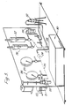
- FIG. 1 shows a pressure source 1 with a pressure regulator 2 operated by a manual control 3.
- the pressure output from the regulator is seen on a gauge 4 and passes to a sample holder 5 between the two parts of which a sample is mounted, the sample having been moistened by any one of water, petroleum distillate, de-natured alcohol or mineral oil, all of a specified characteristics.
- an oil trap 6 Following the passage of gas through the sample is an oil trap 6 and the duct is initially coupled up after that to a so-called bubble point detector 7, wherein output if any being caused to bubble through liquid or to a rotameter 8 which is directly impelled by the flow of liquid.
- the initial breakthrough of gas through the sample is noted by observation of the bubble point detector which sets a zero for a graph which is then drawn by manual correlation of the pressure gauge against the flow rate downstream of the sample as measured by the rotameter 8.
- a pressure regulator 20 such as a Schrader regulator preceded by a filter 21 between it and a source of compressed gas 22, usually compressed air is driven from a synchronous motor (not shown) through belting or other drive train and a ratchet clutch 23. It can be returned to zero by manual intervention on the part 24 of the clutch nearer to the regulator 20.
- a synchronous motor not shown
- a ratchet clutch 23 It can be returned to zero by manual intervention on the part 24 of the clutch nearer to the regulator 20.
- two pressure gauges 26, 27 which can be brought into communication with the line through respective valves.
- the pressure gauges are used for calibration only and they are sensitive in different ranges of pressure, only one being used for any given calibration.
- transducers 28, 29 for pressure and flow-rate respectively.
- the pressure transducer may be of any known type but we have used one of the stressed metal film (also known as bonded foil strain gauge) type which gives an output to an X Y recorder 30 having a pen drivable over graph paper in either or both of the X Y directions in accordance with respective inputs.
- the other input is derived from a flow-rate transducer 29 and we prefer to use a thermal mass flow meter since it is devoid of moving parts.
- these devices are sensing both pressure and flow-rate in the ducting upstream of the sample 31 which is mounted in a standard holder 32 and which optionally may be followed by the standard liquid trap 35 and by a two-way valve 3-4 which can divert flow either to a standard bubble point detector 35 or to standard flow meters 36, 37. Which of these two is connected to the line is selected by respective valves.
- the flow meters 36, 37 which are of the type which is impelled by the flow of gas are used only in calibration of the device.
- the bubble point detector is however used to manually note the initial point of the breakthrough of the gas at which time a tick or similar mark is made manually on the graph paper in the recorder 30 as a safeguard for extra accuracy in determining the origin of the curve which will be obtained.
- calibration is first carried out without a sample in the holder. Gas is run through the system at a pressure similar to the maximum which will be expected to be used in the following test. One or other of the pressure gauges 26, 27 is selected and the output from pressure transducer 28 only is fed to the recorder 30. The correlation between the position of the pen and the reading on the pressure gauges made and if necessary the zeros are then calibrated, with recalibration at the high pressure and so on. Similarly, calibration of the flow-rate is carried out by taking the output from flow-rate transducer 29 only to the recorder and comparing the other reading of the pen with the reading achieved by one of the two direct-impelled flow meters 36 or 37 which may be appropriate to the expected maximum flow during the test. When calibration has been achieved the pressure gauges and the flow meters are switched out of the system.
- the valve 34 is switched over so that the bubble detector is in the circuit, a standard sample which may be for example a filter paper, a sintered micro-filter, a blotting paper, a geological material or any other material of which it is wished to know the porosity, is saturated in Fluorinert FC43 and placed in the holder.
- the automatic drive 23 is coupled to the pressure regulator so there is and automatic and predetermined increase in the pressure applied to the sample and the test is run, achieving a wet curve graph. The test is continued until that line becomes substantially straight, showing substantially complete drying of the sample. The pressure is then returned to zero and the run repeated with the sample still in the holder to obtain the dry curve which is substantially a straight line.
- the two curves are plotted on the same piece of graph paper 32 automatically by the recorder 30 and are then removed for the necessary interpretation.
Landscapes
- Chemical & Material Sciences (AREA)
- Dispersion Chemistry (AREA)
- Physics & Mathematics (AREA)
- Health & Medical Sciences (AREA)
- Life Sciences & Earth Sciences (AREA)
- Analytical Chemistry (AREA)
- Biochemistry (AREA)
- General Health & Medical Sciences (AREA)
- General Physics & Mathematics (AREA)
- Immunology (AREA)
- Pathology (AREA)
- Sampling And Sample Adjustment (AREA)
Claims (14)
Applications Claiming Priority (2)
| Application Number | Priority Date | Filing Date | Title |
|---|---|---|---|
| GB838313635A GB8313635D0 (en) | 1983-05-17 | 1983-05-17 | Porosimeter |
| GB8313635 | 1983-05-17 |
Publications (3)
| Publication Number | Publication Date |
|---|---|
| EP0143837A1 EP0143837A1 (de) | 1985-06-12 |
| EP0143837B1 EP0143837B1 (de) | 1989-01-04 |
| EP0143837B2 true EP0143837B2 (de) | 1992-08-05 |
Family
ID=10542895
Family Applications (1)
| Application Number | Title | Priority Date | Filing Date |
|---|---|---|---|
| EP84902209A Expired EP0143837B2 (de) | 1983-05-17 | 1984-05-17 | Porosimeter und verfahren zur bestimmung der porosität |
Country Status (7)
| Country | Link |
|---|---|
| US (1) | US4718270A (de) |
| EP (1) | EP0143837B2 (de) |
| JP (1) | JPS60501331A (de) |
| AU (1) | AU2968784A (de) |
| DE (1) | DE3475956D1 (de) |
| GB (1) | GB8313635D0 (de) |
| WO (1) | WO1984004593A1 (de) |
Families Citing this family (82)
| Publication number | Priority date | Publication date | Assignee | Title |
|---|---|---|---|---|
| US4864845A (en) * | 1987-09-29 | 1989-09-12 | Board Of Regents University Of Texas System | Electronic field permeameter |
| US5157960A (en) * | 1990-02-06 | 1992-10-27 | Massachusetts Institute Of Technology | Method and apparatus for transient measurement of gas permeability in closed-cell foam insulation |
| US5133219A (en) * | 1991-02-28 | 1992-07-28 | Micromeritics Instrument Corporation | Dynamically balanced, differential gas adsorption appartaus |
| US5219388A (en) * | 1992-01-17 | 1993-06-15 | University Of Florida | Method and apparatus for testing water permeability of concrete |
| US5576480A (en) * | 1992-11-06 | 1996-11-19 | Pall Corporation | System and method for testing the integrity of porous elements |
| JPH08503545A (ja) * | 1992-11-06 | 1996-04-16 | ポール・コーポレーション | 多孔質エレメントの完全性試験のためのシステム及び方法 |
| DE4302137C2 (de) * | 1993-01-27 | 1999-09-02 | Micro Perforation Engineering | Verfahren und Vorrichtung zur optischen Porositätsmessung an einer laufenden Bahn |
| US5442950A (en) * | 1993-10-18 | 1995-08-22 | Saudi Arabian Oil Company | Method and apparatus for determining properties of reservoir rock |
| US5425265A (en) * | 1993-12-20 | 1995-06-20 | Jaisinghani; Rajan A. | Apparatus and method for measuring the capillary pressure distribution of porous materials |
| US20040232076A1 (en) * | 1996-12-20 | 2004-11-25 | Fufang Zha | Scouring method |
| CA2639642C (en) * | 1996-12-20 | 2013-01-15 | Siemens Water Technologies Corp. | Scouring method |
| AUPO709797A0 (en) * | 1997-05-30 | 1997-06-26 | Usf Filtration And Separations Group Inc. | Predicting logarithmic reduction values |
| US6641733B2 (en) * | 1998-09-25 | 2003-11-04 | U. S. Filter Wastewater Group, Inc. | Apparatus and method for cleaning membrane filtration modules |
| FR2773882B1 (fr) * | 1998-01-22 | 2000-03-10 | Tabacs & Allumettes Ind | Permeametre a large plage de mesure |
| WO2000009988A2 (en) * | 1998-08-11 | 2000-02-24 | The Penn State Research Foundation | Rapid method to experimentally measure the gas permeability of micro-perforated films |
| EP1032816B1 (de) * | 1998-08-28 | 2010-07-28 | Imec | Vorrichtung und verfahren zur bestimmung der porosität |
| AUPP985099A0 (en) * | 1999-04-20 | 1999-05-13 | Usf Filtration And Separations Group Inc. | Membrane filtration manifold system |
| AUPQ680100A0 (en) * | 2000-04-10 | 2000-05-11 | Usf Filtration And Separations Group Inc. | Hollow fibre restraining system |
| AUPR064800A0 (en) * | 2000-10-09 | 2000-11-02 | Usf Filtration And Separations Group Inc. | Improved membrane filtration system |
| AUPR094600A0 (en) * | 2000-10-23 | 2000-11-16 | Usf Filtration And Separations Group Inc. | Fibre membrane arrangement |
| AUPR143400A0 (en) * | 2000-11-13 | 2000-12-07 | Usf Filtration And Separations Group Inc. | Modified membranes |
| KR100372908B1 (ko) * | 2000-11-22 | 2003-02-15 | 광주과학기술원 | 용질의 특정분자량 부분제거율을 이용한 막공 크기분포측정방법 및 장치 |
| AUPR421501A0 (en) | 2001-04-04 | 2001-05-03 | U.S. Filter Wastewater Group, Inc. | Potting method |
| AUPR584301A0 (en) * | 2001-06-20 | 2001-07-12 | U.S. Filter Wastewater Group, Inc. | Membrane polymer compositions |
| AUPR692401A0 (en) * | 2001-08-09 | 2001-08-30 | U.S. Filter Wastewater Group, Inc. | Method of cleaning membrane modules |
| AUPR774201A0 (en) * | 2001-09-18 | 2001-10-11 | U.S. Filter Wastewater Group, Inc. | High solids module |
| US6655192B2 (en) | 2001-10-10 | 2003-12-02 | Borgwarner Inc. | Permeameter-porosimeter |
| EP1312408B1 (de) * | 2001-11-16 | 2006-07-19 | US Filter Wastewater Group, Inc. | Methode zur Reinigung von Membranen |
| US7247238B2 (en) * | 2002-02-12 | 2007-07-24 | Siemens Water Technologies Corp. | Poly(ethylene chlorotrifluoroethylene) membranes |
| AUPS300602A0 (en) * | 2002-06-18 | 2002-07-11 | U.S. Filter Wastewater Group, Inc. | Methods of minimising the effect of integrity loss in hollow fibre membrane modules |
| JP4282598B2 (ja) * | 2002-10-10 | 2009-06-24 | シーメンス・ウォーター・テクノロジーズ・コーポレーション | 濾過装置及び該濾過装置を洗浄する方法 |
| AU2002953111A0 (en) * | 2002-12-05 | 2002-12-19 | U. S. Filter Wastewater Group, Inc. | Mixing chamber |
| US6845651B2 (en) * | 2003-04-21 | 2005-01-25 | Porous Materials, Inc. | Quick BET method and apparatus for determining surface area and pore distribution of a sample |
| AU2003903507A0 (en) * | 2003-07-08 | 2003-07-24 | U. S. Filter Wastewater Group, Inc. | Membrane post-treatment |
| JP4611982B2 (ja) | 2003-08-29 | 2011-01-12 | シーメンス・ウォーター・テクノロジーズ・コーポレーション | 逆洗方法 |
| AU2004289373B2 (en) | 2003-11-14 | 2010-07-29 | Evoqua Water Technologies Llc | Improved module cleaning method |
| WO2005092799A1 (en) | 2004-03-26 | 2005-10-06 | U.S. Filter Wastewater Group, Inc. | Process and apparatus for purifying impure water using microfiltration or ultrafiltration in combination with reverse osmosis |
| US20050229679A1 (en) * | 2004-04-16 | 2005-10-20 | Porous Materials, Inc. | Automated clamp-on sample chamber for flow porometry and a method of using same |
| JP2007535398A (ja) | 2004-04-22 | 2007-12-06 | シーメンス ウォーター テクノロジース コーポレイション | 有機物質を消化するためのメンブレンバイオリアクタおよび処理槽を含む濾過装置ならびに廃液処理方法 |
| JP2008504122A (ja) * | 2004-07-02 | 2008-02-14 | シーメンス・ウォーター・テクノロジーズ・コーポレーション | 気体輸送膜 |
| US8524794B2 (en) | 2004-07-05 | 2013-09-03 | Siemens Industry, Inc. | Hydrophilic membranes |
| NZ588094A (en) * | 2004-08-20 | 2012-04-27 | Siemens Water Tech Corp | Potting head for hollow fibre filter module |
| JP4838248B2 (ja) * | 2004-09-07 | 2011-12-14 | シーメンス・ウォーター・テクノロジーズ・コーポレーション | 逆洗液体廃棄物の低減 |
| US8506806B2 (en) | 2004-09-14 | 2013-08-13 | Siemens Industry, Inc. | Methods and apparatus for removing solids from a membrane module |
| WO2006029465A1 (en) | 2004-09-15 | 2006-03-23 | Siemens Water Technologies Corp. | Continuously variable aeration |
| CA2585861A1 (en) * | 2004-11-02 | 2006-05-11 | Siemens Water Technologies Corp. | Membrane filtration module with fluid retaining means |
| US7591950B2 (en) * | 2004-11-02 | 2009-09-22 | Siemens Water Technologies Corp. | Submerged cross-flow filtration |
| WO2006058384A1 (en) * | 2004-12-03 | 2006-06-08 | Siemens Water Technologies Corp. | Membrane post treatment |
| EP1835985B1 (de) | 2004-12-24 | 2012-03-14 | Siemens Industry, Inc. | Reinigung in membranfiltrationssystemen |
| JP2008525167A (ja) | 2004-12-24 | 2008-07-17 | シーメンス・ウォーター・テクノロジーズ・コーポレーション | 簡易ガス洗浄方法および当該技術分野の装置 |
| KR20080005993A (ko) | 2005-04-29 | 2008-01-15 | 지멘스 워터 테크놀로지스 코포레이션 | 막 필터의 화학 세정 |
| NZ563980A (en) * | 2005-06-20 | 2011-07-29 | Siemens Water Tech Corp | Cross linking treatment of polymer membranes |
| KR20080031956A (ko) | 2005-07-14 | 2008-04-11 | 지멘스 워터 테크놀로지스 코포레이션 | 막의 모노퍼술페이트 처리 방법 |
| SG164499A1 (en) * | 2005-08-22 | 2010-09-29 | Siemens Water Tech Corp | An assembly for water filtration using a tube manifold to minimise backwash |
| US20070138090A1 (en) * | 2005-10-05 | 2007-06-21 | Jordan Edward J | Method and apparatus for treating wastewater |
| WO2007044345A2 (en) * | 2005-10-05 | 2007-04-19 | Siemens Water Technologies Corp. | Method and apparatus for treating wastewater |
| WO2007044442A2 (en) * | 2005-10-05 | 2007-04-19 | Siemens Water Technologies Corp. | Method and system for treating wastewater |
| US7430895B2 (en) * | 2005-11-18 | 2008-10-07 | International Business Machines Corporation | Apparatus and method for inspecting quality of molded foam parts |
| US7455765B2 (en) | 2006-01-25 | 2008-11-25 | Siemens Water Technologies Corp. | Wastewater treatment system and method |
| KR20090034976A (ko) * | 2006-07-14 | 2009-04-08 | 지멘스 워터 테크놀로지스 코포레이션 | 막의 개선된 모노퍼술페이트 처리 방법 |
| US8293098B2 (en) | 2006-10-24 | 2012-10-23 | Siemens Industry, Inc. | Infiltration/inflow control for membrane bioreactor |
| US8318028B2 (en) | 2007-04-02 | 2012-11-27 | Siemens Industry, Inc. | Infiltration/inflow control for membrane bioreactor |
| US9764288B2 (en) | 2007-04-04 | 2017-09-19 | Evoqua Water Technologies Llc | Membrane module protection |
| KR20130135980A (ko) | 2007-05-29 | 2013-12-11 | 지멘스 인더스트리 인코포레이티드 | 펄스형 공기리프트 펌프를 이용한 막 세정 방법 및 장치 |
| CA2731774A1 (en) | 2008-07-24 | 2010-01-28 | Siemens Water Technologies Corp. | Frame system for membrane filtration modules |
| AU2009282912B2 (en) | 2008-08-20 | 2014-11-27 | Evoqua Water Technologies Llc | Improved membrane system backwash energy efficiency |
| AU2010101488B4 (en) | 2009-06-11 | 2013-05-02 | Evoqua Water Technologies Llc | Methods for cleaning a porous polymeric membrane and a kit for cleaning a porous polymeric membrane |
| WO2011079062A1 (en) * | 2009-12-21 | 2011-06-30 | Siemens Industry, Inc. | Charged porous polymeric membranes and their preparation |
| US9914097B2 (en) | 2010-04-30 | 2018-03-13 | Evoqua Water Technologies Llc | Fluid flow distribution device |
| WO2012040412A1 (en) | 2010-09-24 | 2012-03-29 | Siemens Industry, Inc. | Fluid control manifold for membrane filtration system |
| CA2850522C (en) | 2011-09-30 | 2021-03-16 | Evoqua Water Technologies Llc | Shut-off valve for isolation of hollow fiber membrane filtration module |
| US9604166B2 (en) | 2011-09-30 | 2017-03-28 | Evoqua Water Technologies Llc | Manifold arrangement |
| KR102108593B1 (ko) | 2012-06-28 | 2020-05-29 | 에보쿠아 워터 테크놀로지스 엘엘씨 | 포팅 방법 |
| KR20150054918A (ko) | 2012-09-14 | 2015-05-20 | 에보쿠아 워터 테크놀로지스 엘엘씨 | 막을 위한 중합체 블렌드 |
| US9962865B2 (en) | 2012-09-26 | 2018-05-08 | Evoqua Water Technologies Llc | Membrane potting methods |
| AU2013324056B2 (en) | 2012-09-26 | 2017-11-16 | Evoqua Water Technologies Llc | Membrane securement device |
| WO2014052139A1 (en) | 2012-09-27 | 2014-04-03 | Evoqua Water Technologies Llc | Gas scouring apparatus for immersed membranes |
| HUE061765T2 (hu) | 2013-10-02 | 2023-08-28 | Rohm & Haas Electronic Mat Singapore Pte Ltd | Berendezés membrán filtrációs modul javítására |
| WO2016029922A1 (en) | 2014-08-27 | 2016-03-03 | W.L. Gore & Associates Gmbh | Waterproof and water vapor permeable laminate |
| EP3322511B1 (de) | 2015-07-14 | 2022-09-07 | Rohm & Haas Electronic Materials Singapore Pte. Ltd | Belüftungsvorrichtung für filtrationssystem |
| CN112304841B (zh) * | 2020-09-24 | 2023-04-25 | 中国石油大学(华东) | 一种岩石孔隙结构仿真测试系统及模拟试验方法 |
| CN115266511B (zh) * | 2021-04-30 | 2026-01-27 | 中国石油天然气股份有限公司 | 预测岩石孔隙特征数据的方法及装置 |
Family Cites Families (16)
| Publication number | Priority date | Publication date | Assignee | Title |
|---|---|---|---|---|
| US2861451A (en) * | 1954-11-29 | 1958-11-25 | Sheffield Corp | Fluid leakage gauging device |
| DE1063832B (de) * | 1956-01-14 | 1959-08-20 | Waldhof Zellstoff Fab | Gas- oder Luftdurchlaessigkeitspruefgeraet |
| US2842958A (en) * | 1956-01-27 | 1958-07-15 | Pure Oil Co | Apparatus for measuring flow characteristics of porous specimens by displacement |
| US3504422A (en) * | 1968-01-19 | 1970-04-07 | Bell Aerospace Corp | Method of making a depth-type filter media |
| DE2434736C3 (de) * | 1974-07-19 | 1980-06-19 | Hauni-Werke Koerber & Co Kg, 2050 Hamburg | Verfahren und Anordnung zum Prüfen der Umhüllung stabf örmiger Artikel der tabakverarbeitenden Industrie |
| US4191046A (en) * | 1977-07-01 | 1980-03-04 | British-American Tobacco Company Limited | Permeability meters |
| GB2018436B (en) * | 1977-11-04 | 1982-07-07 | Cigarette Components Ltd | Porosity measurement |
| US4198853A (en) * | 1977-11-04 | 1980-04-22 | American Filtrona Corporation | Porosity measurement |
| US4198854A (en) * | 1978-12-07 | 1980-04-22 | Philip Morris Incorporated | Method and apparatus for measuring porosity |
| US4213327A (en) * | 1979-01-11 | 1980-07-22 | General Motors Corporation | Flow bench |
| IT1133512B (it) * | 1980-10-07 | 1986-07-09 | Cir Spa Divisione Sasib | Metodo e dispositivo per il controllo elettropneumatico della permeabilita longitudinale e o trasversale di sigarette |
| GB2095411B (en) * | 1981-02-09 | 1985-06-12 | Filtrona Ltd | Paper porosity |
| DE3111318C2 (de) * | 1981-03-23 | 1983-03-17 | B.A.T. Cigaretten-Fabriken Gmbh, 2000 Hamburg | Verfahren zur Bestimmung des Zugwiderstandes und/oder der Gasdurchlässigkeit eines Prüflings sowie Einrichtung zur Durchführung eines solchen Verfahrens |
| DE3117399C2 (de) * | 1981-05-02 | 1983-02-10 | Bruno Ing.(grad.) 8931 Reichertshofen Huschke | Prüfeinrichtung für Filter, insbesondere Sterilfilter |
| JPS5965241A (ja) * | 1982-10-06 | 1984-04-13 | Shokubai Kasei Kogyo Kk | 細孔分布解析装置 |
| US4506542A (en) * | 1983-04-22 | 1985-03-26 | Chandler Engineering Company | Apparatus and procedure for relative permeability measurements |
-
1983
- 1983-05-17 GB GB838313635A patent/GB8313635D0/en active Pending
-
1984
- 1984-05-17 EP EP84902209A patent/EP0143837B2/de not_active Expired
- 1984-05-17 WO PCT/GB1984/000170 patent/WO1984004593A1/en not_active Ceased
- 1984-05-17 JP JP59502311A patent/JPS60501331A/ja active Granted
- 1984-05-17 DE DE8484902209T patent/DE3475956D1/de not_active Expired
- 1984-05-17 US US06/694,555 patent/US4718270A/en not_active Expired - Lifetime
- 1984-05-17 AU AU29687/84A patent/AU2968784A/en not_active Abandoned
Also Published As
| Publication number | Publication date |
|---|---|
| EP0143837A1 (de) | 1985-06-12 |
| AU2968784A (en) | 1984-12-04 |
| DE3475956D1 (en) | 1989-02-09 |
| US4718270A (en) | 1988-01-12 |
| GB8313635D0 (en) | 1983-06-22 |
| JPH058772B2 (de) | 1993-02-03 |
| JPS60501331A (ja) | 1985-08-15 |
| EP0143837B1 (de) | 1989-01-04 |
| WO1984004593A1 (en) | 1984-11-22 |
Similar Documents
| Publication | Publication Date | Title |
|---|---|---|
| EP0143837B2 (de) | Porosimeter und verfahren zur bestimmung der porosität | |
| Walls et al. | Effects of pressure and partial water saturation on gas permeability in tight sands: experimental results | |
| US4744240A (en) | Method for determining the bubble point or the largest pore of membranes or of filter materials | |
| US4555934A (en) | Method and apparatus for nonsteady state testing of permeability | |
| JP3381991B2 (ja) | 透水性測定装置並びにこれを使用する透水性測定方法 | |
| CN108827853B (zh) | 基于核磁共振的致密储层岩电测量装置及测量方法 | |
| US4566326A (en) | Automatic volumetric sorption analyzer | |
| US2861451A (en) | Fluid leakage gauging device | |
| JPS63502450A (ja) | 緊密コアプラグの細孔容量と浸透率を測定する方法および装置 | |
| US3839900A (en) | Air leakage detector | |
| US3499315A (en) | Contamination determination in a fluid system | |
| US3939695A (en) | Apparatus for detecting leaks | |
| US4671100A (en) | Permeameter | |
| US3893332A (en) | Leakage test system | |
| EP0720011A1 (de) | Verfahren zur Dichtebestimmung von Kernreaktor-Brennstofftabletten mittels Gasverdrängung | |
| CN104237142A (zh) | 材料放气对光学透过率影响分析试验系统 | |
| GB2140163A (en) | Porosimeter and methods of assessing porosity | |
| RU2186365C2 (ru) | Способ определения параметров пористости материалов | |
| US4663962A (en) | Method and a device for detecting leakage of a tube section | |
| JP3712761B2 (ja) | 液体試薬の容積測定方法 | |
| US4462248A (en) | Automatic pressure/flow device | |
| Agus et al. | A triaxial permeameter for unsaturated soils | |
| US4019379A (en) | Pneumatic roughness measurer | |
| Weaver | Electrical Measurement of Water Vapor with Hygroscopic Film | |
| Park | Aids for the Analyst-Semimicro Gas Permeability Apparatus for Sheet Material |
Legal Events
| Date | Code | Title | Description |
|---|---|---|---|
| PUAI | Public reference made under article 153(3) epc to a published international application that has entered the european phase |
Free format text: ORIGINAL CODE: 0009012 |
|
| 17P | Request for examination filed |
Effective date: 19850121 |
|
| AK | Designated contracting states |
Designated state(s): DE FR GB |
|
| 17Q | First examination report despatched |
Effective date: 19860428 |
|
| D17Q | First examination report despatched (deleted) | ||
| GRAA | (expected) grant |
Free format text: ORIGINAL CODE: 0009210 |
|
| AK | Designated contracting states |
Kind code of ref document: B1 Designated state(s): DE FR GB |
|
| REF | Corresponds to: |
Ref document number: 3475956 Country of ref document: DE Date of ref document: 19890209 |
|
| ET | Fr: translation filed | ||
| PLBI | Opposition filed |
Free format text: ORIGINAL CODE: 0009260 |
|
| 26 | Opposition filed |
Opponent name: ENKA AG Effective date: 19890912 |
|
| PUAH | Patent maintained in amended form |
Free format text: ORIGINAL CODE: 0009272 |
|
| STAA | Information on the status of an ep patent application or granted ep patent |
Free format text: STATUS: PATENT MAINTAINED AS AMENDED |
|
| 27A | Patent maintained in amended form |
Effective date: 19920805 |
|
| AK | Designated contracting states |
Kind code of ref document: B2 Designated state(s): DE FR GB |
|
| ET3 | Fr: translation filed ** decision concerning opposition | ||
| REG | Reference to a national code |
Ref country code: GB Ref legal event code: IF02 |
|
| REG | Reference to a national code |
Ref country code: GB Ref legal event code: 732E |
|
| REG | Reference to a national code |
Ref country code: FR Ref legal event code: TP Ref country code: FR Ref legal event code: CD Ref country code: FR Ref legal event code: CA |
|
| PGFP | Annual fee paid to national office [announced via postgrant information from national office to epo] |
Ref country code: GB Payment date: 20030514 Year of fee payment: 20 |
|
| PGFP | Annual fee paid to national office [announced via postgrant information from national office to epo] |
Ref country code: FR Payment date: 20030520 Year of fee payment: 20 |
|
| PGFP | Annual fee paid to national office [announced via postgrant information from national office to epo] |
Ref country code: DE Payment date: 20030626 Year of fee payment: 20 |
|
| PG25 | Lapsed in a contracting state [announced via postgrant information from national office to epo] |
Ref country code: GB Free format text: LAPSE BECAUSE OF EXPIRATION OF PROTECTION Effective date: 20040516 |
|
| REG | Reference to a national code |
Ref country code: GB Ref legal event code: PE20 |