EP0143697A2 - Modular-Diffusionsofen zur vakuum-chemischen Dampfphasenabscheidung - Google Patents
Modular-Diffusionsofen zur vakuum-chemischen Dampfphasenabscheidung Download PDFInfo
- Publication number
- EP0143697A2 EP0143697A2 EP84402333A EP84402333A EP0143697A2 EP 0143697 A2 EP0143697 A2 EP 0143697A2 EP 84402333 A EP84402333 A EP 84402333A EP 84402333 A EP84402333 A EP 84402333A EP 0143697 A2 EP0143697 A2 EP 0143697A2
- Authority
- EP
- European Patent Office
- Prior art keywords
- diffusion tube
- reaction chamber
- diffusion
- tube
- furnace according
- Prior art date
- Legal status (The legal status is an assumption and is not a legal conclusion. Google has not performed a legal analysis and makes no representation as to the accuracy of the status listed.)
- Withdrawn
Links
Images
Classifications
-
- C—CHEMISTRY; METALLURGY
- C30—CRYSTAL GROWTH
- C30B—SINGLE-CRYSTAL GROWTH; UNIDIRECTIONAL SOLIDIFICATION OF EUTECTIC MATERIAL OR UNIDIRECTIONAL DEMIXING OF EUTECTOID MATERIAL; REFINING BY ZONE-MELTING OF MATERIAL; PRODUCTION OF A HOMOGENEOUS POLYCRYSTALLINE MATERIAL WITH DEFINED STRUCTURE; SINGLE CRYSTALS OR HOMOGENEOUS POLYCRYSTALLINE MATERIAL WITH DEFINED STRUCTURE; AFTER-TREATMENT OF SINGLE CRYSTALS OR A HOMOGENEOUS POLYCRYSTALLINE MATERIAL WITH DEFINED STRUCTURE; APPARATUS THEREFOR
- C30B31/00—Diffusion or doping processes for single crystals or homogeneous polycrystalline material with defined structure; Apparatus therefor
- C30B31/06—Diffusion or doping processes for single crystals or homogeneous polycrystalline material with defined structure; Apparatus therefor by contacting with diffusion material in the gaseous state
- C30B31/10—Reaction chambers; Selection of materials therefor
- C30B31/103—Mechanisms for moving either the charge or heater
-
- C—CHEMISTRY; METALLURGY
- C23—COATING METALLIC MATERIAL; COATING MATERIAL WITH METALLIC MATERIAL; CHEMICAL SURFACE TREATMENT; DIFFUSION TREATMENT OF METALLIC MATERIAL; COATING BY VACUUM EVAPORATION, BY SPUTTERING, BY ION IMPLANTATION OR BY CHEMICAL VAPOUR DEPOSITION, IN GENERAL; INHIBITING CORROSION OF METALLIC MATERIAL OR INCRUSTATION IN GENERAL
- C23C—COATING METALLIC MATERIAL; COATING MATERIAL WITH METALLIC MATERIAL; SURFACE TREATMENT OF METALLIC MATERIAL BY DIFFUSION INTO THE SURFACE, BY CHEMICAL CONVERSION OR SUBSTITUTION; COATING BY VACUUM EVAPORATION, BY SPUTTERING, BY ION IMPLANTATION OR BY CHEMICAL VAPOUR DEPOSITION, IN GENERAL
- C23C16/00—Chemical coating by decomposition of gaseous compounds, without leaving reaction products of surface material in the coating, i.e. chemical vapour deposition [CVD] processes
- C23C16/44—Chemical coating by decomposition of gaseous compounds, without leaving reaction products of surface material in the coating, i.e. chemical vapour deposition [CVD] processes characterised by the method of coating
- C23C16/455—Chemical coating by decomposition of gaseous compounds, without leaving reaction products of surface material in the coating, i.e. chemical vapour deposition [CVD] processes characterised by the method of coating characterised by the method used for introducing gases into reaction chamber or for modifying gas flows in reaction chamber
- C23C16/45563—Gas nozzles
- C23C16/45578—Elongated nozzles, tubes with holes
Definitions
- This invention is directed to the field of integrated circuit fabrication, and more particularly, to a novel modular V-CVD diffusion furnace.
- V-CVD diffusion furnaces Semiconductor wafers are typically batch processed in vacuum chemical vapor deposition (V-CVD) diffusion furnaces to form thin-film thereon of selected characteristics during various integrated circuit fabrication processes.
- V-CVD diffusion furnaces include a cylindrical diffusion tube having on one end an opening dimensioned to accept a batch of wafers to be processed, a tapering neck on its other end in communication with a controlled source of vacuum, and one or more gas-injection tubes slidably received in the tapering neck of the cylindrical diffusion tube.
- Reactant in gas phase injected into the diffusion furnace pyrolytically decomposes and deposits thin-film in solid phase not only on the semiconductor wafers, but also on the inside surface of the diffusion tube itself as well as on the surfaces of the one or more gas-injection tubes.
- the batch of coated wafers is then removed from the furnace, and the same or another process is run on another batch of wafers. With each such usage, the covering thickness of the thin-film on the walls of the furnace and tubes increases, necessitating chemical etching to remove the build-up therefrom at regular intervals.
- the heretofore known diffusion furnaces are disadvantageous due to the considerable labor and lost-revenue costs incurred each time it is necessary to remove the deposit build-up.
- the diffusion furnace is turned off to allow it to cool to room temperature. Thereafter, the diffusion tube and gas injection tubes are disconnected from the gas control subsystem, the vacuum subsystem, and the heating subsystem, and mechanically removed from the diffusion furnace. Prior to reconnection, air that has leaked into the disconnected gas control subsystem must be purged.
- the cleaned diffusion tube is then reconnected to the heating, vacuum, and gas subsystems.
- the one or more cleaned gas injection tubes are then reinserted and reconnected.
- the abovedescribed cleaning procedure takes from one to two days during which the furnace is inoperable with consequent loss of revenues.
- the heretofore known diffusion furnaces are additionally disadvantageous in that the reconnection of the gas injection tubes is a comparatively complex procedure. Due to the difficulty of precisely realigning the gas injection tubes in the sloping walls of the tapering neck of the diffusion tube, injection tube reconnection is both a tedious and a time consuming procedure.
- the heretofore known diffusion furnaces are further disadvantageous due to the fact that a diffusion tube having a tapering neck is itself an expensive component to fabricate, procure, repair, and replace.
- the tapering neck is comparatively fragile, and may break in use and during handling as a result of internal strain induced by both mechanical gas injection tube insertion stress and thermal stress during the operation of the furnace .
- the replacement of a broken tube involves the same costly and time- consuming procedure used for furnace cleaning, and may possibly result in the contamination of a batch of wafers should breakage arise in use.
- the vacuum chemical vapor deposition diffusion (V-CV D ) furnace of the present invention overcomes these and other disadvantages and contemplates a modular construction that allows the cleaning and replacement of the diffusion tube without cooling the diffusion furnace to ambient and without disconnecting it from its supporting subsystems, and allows the cleaning and expeditious replacement of the gas injection tubes in a manner that ensures precise re-alignment.
- the novel modular V-CVD diffusion furnace of the present invention has a simple, symmetrical construction that is comparatively inexpensive and durable, that has a long operating life, and that results in considerably increased profits due to its comparatively low down-time.
- the modular V-CVD diffusion furnace of the present invention includes a cylindrical quartz diffusion tube having open ends. First and second integral annular flanges each surrounding an open end are provided on the tube.
- a cylindrical quartz liner having open ends is slidably mounted in the cylindrical diffusion tube.
- a first metal door having a central aperture dimensioned to allow the insertion and removal therethrough of a batch of semiconductor wafers is removably fastened in air-tight sealing engagement with the first annular flange of the cylindrical diffusion tube.
- a liner that is coated with a thick deposit is readily slidably removed from the diffusion tube, and replaced by a clean liner, while the diffusion furnace is both still hot and connected to its supporting subsystems.
- One or more gas injection tubes that are coated with a thick deposit are likewise slidably removed from the injection tube receiving apertures provided in the second door, and clean tubes are readily replaced in precise alignment, likewise while the furnace is both still hot and connected to its supporting subsystems.
- the metal doors due to their rugged construction, are substantially free of mechanically and thermally induced breakage.
- novel modular V-CVD diffusion furnace of the present invention extends the interval between routine down-time cleaning of the diffusion tube by a factor between twenty and fifty over the heretofore known furnaces, thereby providing considerable saving in time and labor, and a significantly enhanced processing throughput capability.
- the furnace 10 includes a symmetrical diffusion tube 12 having open ends that defines a longitudinally extending reaction chamber 14.
- the tube 12 is preferably cylindrically shaped and is fashioned from any suitable high-temperature material such as quartz.
- Annular quartz flanges 16, 18 are integrally formed with the tube 12 respectively surrounding the open ends thereof.
- a heating system generally designated 20 is coupled to the diffusion tube 12 to controllably maintain a selected temperature in the reaction chamber 14.
- the heating system 20 preferably includes a resistance element 22 coiled peripherally around the diffusion tube 12 that is connected to a heat control system 24.
- the heat control system 24 is operative in known manner to selectively energize coil 22 to establish an intended temperature in the chamber 14.
- One or more thermocouples, not shown, are positioned in the chamber 14 and electrically connected to the heat control system 24 to precisely maintain a selected temperature in the chamber 14 to within a selected tolerance.
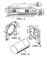
- a first door generally designated 26 having a central aperture 28 is removably fastened in air-tight sealing engagement with the annular flange 16 via an O-ring 30.
- the door 26 includes a plate 32, preferably fashioned from any suitable metal such as stainless steel, having upstanding integral spaced support legs 34, 36.
- An annular groove 38 is provided circumferentially around the central opening 28 that is dimensioned to accept the 0-ring 30 ( Figure 1).
- a plurality of apertures 40 are provided peripherally around the groove 38 and through the plate 32 to provide mounting openings for removably fastening the plate 32 to the flange 16 ( Figure 1).
- a plurality of radially extending bores 42 defining gas injection ports are provided through the circumferential wall of the door 26 that are individually in communication with the chamber 14 ( Figure 1) for controllably injecting reactant in gas phase thereinto as illustrated at 44 ( Figure 1).
- a boat loader generally designated at 46 is removably fastened in air-tight sealing engagement with the first door 26.
- the boat loader 46 includes a plate 47 having a longitudinally extending cantilevered arm 48. Although a cantilevered arm is illustrated, it is noted that carriage-type and wheelbarrow-type arms can be employed as well.
- a plurality of semiconductor wafers 5 p are supported in a boat 51 of conventional design in longitudinally spaced apart relation, with the plane of the wafers being generally coincident with the vertical plane.
- the plate 47 of the boat loader 46 is connected to a motor that controls its translation, not illustrated, for inserting the arm 48 into the reaction chamber 14 and for removing the arm out of the reaction chamber, and therewith the boat-loaded wafers 50.
- the plate 47 of the boat loader 46 is sealed to the door 26 via an 0-ring 52.
- a second door generally designated 54 is removably fastened to the annular flange 18 in air-tight sealing engagement therewith via an O-ring 53.
- the door 54 includes a plate 55, preferably fastened from any suitable metal such as stainless steel, having upstanding integral spaced support legs 56, 57.
- the plate 55 is provided with a central aperture 58 for connection to a controlled source of vacuum, an annular groove 60 surrounding the aperture 58 adapted to accept the O-ring 53 (Fig.
- a plurality of apertures 68 are provided peripherally around the groove 60 and through the plate 55 to provide mounting openings for removably fastening the plate 55 to the annular flange 18 ( Figure 1).
- a vacuum unit 70 is connected to the bore 58 ( Figure 3) via a coupling 72 for controllably maintaining a.selected vacuum condition in the chamber 14.
- a plurality of gas-injection tubes 74 having apertures 75 are slidably mounted through the precisely aligned apertures 66 ( Figure 3) and are held in air-tight sealing engagement with the confronting walls of the openings 66 by any suitable gasket 76 such as the Ultra-Torr fitting commercially available from Cambridge Valve and Fitting Co., Cambridge, Massachusetts.
- Each of the injection tubes 74 are operatively connected to a gas-injection system 78.
- the gas-injection system 78 is operative to controllably introduce preselected reactant in gas phase into the reaction chamber 14 selected for any one of various V-CVD processes well-known to those skilled in the art.
- a liner generally designated 80 is slidably inserted into the diffusion tube 12.
- the liner 80 preferably includes a cylinder 82 having open ends fashioned from any suitable high-temperature material such as quartz.
- the dimension of the cylinder 82 is selected to be just less than the longitudinal dimension of the diffusion tube 12, and has an outside diameter selected to be just less than the inside diameter of the cylindrical diffusion tube 12.
- the gas-injection system 78 injects through the plurality of apertures 75 of the gas-injection tubes 74 reactant in gas phase into the reaction chamber 14, which is maintained at a selected temperature by the heating control system 24, and under precise vacuum conditions by the vacuum system 70.
- Gas injected through the ports 44 into the chamber 14 pyrolytically decompose with the reactant in gas phase injected through the aperture 75 of the tubes 74 to deposit thin-film in solid phase on the planar surfaces of the wafers 50 as well as on the gas-injection tubes 74 and on the liner 80.
- the solid- phase deposits build up to layers on both the liner and the injection tubes requiring their cleaning by chemical etching or other suitable technique.
- the door 26 is unfastened from the flange 16, and the soiled liner 80 is slidably removed from the diffusion tube 12 and replaced by a clean liner while the furnace is still warm without having to disconnect the vacuum system 70, the gas-injection system 78, or the heating system 20, as in the heretofore known devices. Moreover, it will be appreciated that it is not necessary to purge the gas lines as in the heretofore known devices.
- the door 26 is rapidly fastened again in air-tight sealing egagement with the flange 16, and the boat loader 46 can introduce a new batch of wafers into the reaction chamber 14 for processing without requiring the shutdown of the furnace, thereby resulting in considerable savings of labor, and eliminating costly down-time.
- the soiled tubes 74 are disconnected from the gas-injection system 78, are simply slidably removed out of the apertures 66 provided therefor in the door 54, and are replaced by clean injection tubes while the furnace is still warm and again without requiring disconnection from the vacuum or heating systems. Due to the precise alignment of the gas-injection tube receiving apertures 66 (Fig. 3), the placement of the clean tubes is automatically aligned to within close tolerance thereby eliminating the need to provide any additional fine-turning.
- the stainless steel door 54 due to its rugged construction, is not subject to thermal or mechanical stress- induced breakage.
- the symmetrical tube 12 is itself comparatively inexpensive to fabricate, procure, replace, and maintain.
Landscapes
- Chemical & Material Sciences (AREA)
- Engineering & Computer Science (AREA)
- Materials Engineering (AREA)
- Metallurgy (AREA)
- Organic Chemistry (AREA)
- General Chemical & Material Sciences (AREA)
- Chemical Kinetics & Catalysis (AREA)
- Mechanical Engineering (AREA)
- Crystallography & Structural Chemistry (AREA)
- Chemical Vapour Deposition (AREA)
Applications Claiming Priority (2)
| Application Number | Priority Date | Filing Date | Title |
|---|---|---|---|
| US55245483A | 1983-11-16 | 1983-11-16 | |
| US552454 | 1983-11-16 |
Publications (2)
| Publication Number | Publication Date |
|---|---|
| EP0143697A2 true EP0143697A2 (de) | 1985-06-05 |
| EP0143697A3 EP0143697A3 (de) | 1987-07-15 |
Family
ID=24205407
Family Applications (1)
| Application Number | Title | Priority Date | Filing Date |
|---|---|---|---|
| EP84402333A Withdrawn EP0143697A3 (de) | 1983-11-16 | 1984-11-16 | Modular-Diffusionsofen zur vakuum-chemischen Dampfphasenabscheidung |
Country Status (3)
| Country | Link |
|---|---|
| EP (1) | EP0143697A3 (de) |
| JP (1) | JPS60116768A (de) |
| CA (1) | CA1247504A (de) |
Cited By (8)
| Publication number | Priority date | Publication date | Assignee | Title |
|---|---|---|---|---|
| FR2589887A1 (fr) * | 1985-11-14 | 1987-05-15 | Semy Engineering | Procede et reacteur de depot de couches de siliciure |
| EP0221429A3 (de) * | 1985-11-08 | 1987-08-26 | Focus Semiconductor Systems, Inc. | CVD-Reaktor |
| EP0301567A3 (de) * | 1987-07-30 | 1989-06-14 | Telog Systems GmbH | Vorrichtung und Verfahren zur Oberflächenbehandlung von Materialien |
| US6716288B2 (en) | 2000-01-24 | 2004-04-06 | Semiconductor300 Gmbh & Co. Kg | Reactor for manufacturing a semiconductor device |
| CN106839775A (zh) * | 2017-03-16 | 2017-06-13 | 宁波连通设备集团有限公司 | 一种加热炉的模块化制造方法及用该方法制造的加热炉 |
| CN110527987A (zh) * | 2018-11-19 | 2019-12-03 | 北京北方华创微电子装备有限公司 | 反应腔室 |
| CN115306163A (zh) * | 2022-09-14 | 2022-11-08 | 中化二建集团有限公司 | 石化工程管式加热炉模块化建造施工方法 |
| EP4219021A1 (de) * | 2022-01-27 | 2023-08-02 | Uniwersytet Jagiellonski | Verfahren und system zum aufbringen einer flüssigkeit auf ein objekt in einem vakuumsystem |
Family Cites Families (4)
| Publication number | Priority date | Publication date | Assignee | Title |
|---|---|---|---|---|
| JPS5588840A (en) * | 1978-12-27 | 1980-07-04 | Hitachi Ltd | Heating reaction furnace |
| JPS5754329A (en) * | 1980-09-19 | 1982-03-31 | Hitachi Ltd | Decompressed vapor-phase growing device |
| JPS57159015A (en) * | 1981-03-26 | 1982-10-01 | Nec Corp | Film growing device |
| DE3366974D1 (en) * | 1982-04-29 | 1986-11-20 | Heraeus Schott Quarzschmelze | Apparatus for introducing silicon wafers in magazines into a furnace |
-
1984
- 1984-11-15 CA CA000467886A patent/CA1247504A/en not_active Expired
- 1984-11-15 JP JP24155284A patent/JPS60116768A/ja active Pending
- 1984-11-16 EP EP84402333A patent/EP0143697A3/de not_active Withdrawn
Cited By (8)
| Publication number | Priority date | Publication date | Assignee | Title |
|---|---|---|---|---|
| EP0221429A3 (de) * | 1985-11-08 | 1987-08-26 | Focus Semiconductor Systems, Inc. | CVD-Reaktor |
| FR2589887A1 (fr) * | 1985-11-14 | 1987-05-15 | Semy Engineering | Procede et reacteur de depot de couches de siliciure |
| EP0301567A3 (de) * | 1987-07-30 | 1989-06-14 | Telog Systems GmbH | Vorrichtung und Verfahren zur Oberflächenbehandlung von Materialien |
| US6716288B2 (en) | 2000-01-24 | 2004-04-06 | Semiconductor300 Gmbh & Co. Kg | Reactor for manufacturing a semiconductor device |
| CN106839775A (zh) * | 2017-03-16 | 2017-06-13 | 宁波连通设备集团有限公司 | 一种加热炉的模块化制造方法及用该方法制造的加热炉 |
| CN110527987A (zh) * | 2018-11-19 | 2019-12-03 | 北京北方华创微电子装备有限公司 | 反应腔室 |
| EP4219021A1 (de) * | 2022-01-27 | 2023-08-02 | Uniwersytet Jagiellonski | Verfahren und system zum aufbringen einer flüssigkeit auf ein objekt in einem vakuumsystem |
| CN115306163A (zh) * | 2022-09-14 | 2022-11-08 | 中化二建集团有限公司 | 石化工程管式加热炉模块化建造施工方法 |
Also Published As
| Publication number | Publication date |
|---|---|
| CA1247504A (en) | 1988-12-28 |
| JPS60116768A (ja) | 1985-06-24 |
| EP0143697A3 (de) | 1987-07-15 |
Similar Documents
| Publication | Publication Date | Title |
|---|---|---|
| US4573431A (en) | Modular V-CVD diffusion furnace | |
| US6283175B1 (en) | Enveloping device and vertical heat-treating apparatus for semiconductor process system | |
| KR880000472B1 (ko) | 화학 증착 장치 및 방법 | |
| US5456757A (en) | Susceptor for vapor deposition | |
| US5616208A (en) | Vacuum processing apparatus, vacuum processing method, and method for cleaning the vacuum processing apparatus | |
| KR100625890B1 (ko) | 다수의 반도체 웨이퍼 처리 장치 | |
| US4640223A (en) | Chemical vapor deposition reactor | |
| CN107134424B (zh) | 石英管保持构造和使用了石英管保持构造的热处理装置 | |
| WO2000060653A1 (en) | Plasma treatment device, its maintenance method and its installation method | |
| JPWO2000060653A1 (ja) | プラズマ処理装置,そのメンテナンス方法およびその施工方法 | |
| KR20040010620A (ko) | 처리 장치 및 처리 방법 | |
| EP0143697A2 (de) | Modular-Diffusionsofen zur vakuum-chemischen Dampfphasenabscheidung | |
| US4556584A (en) | Method for providing substantially waste-free chemical vapor deposition of thin-film on semiconductor substrates | |
| TW202246569A (zh) | 用於腔室內電阻加熱元件的腔室主體饋通 | |
| US6538237B1 (en) | Apparatus for holding a quartz furnace | |
| KR100820527B1 (ko) | 대기로부터 다중 영역 히터를 격리하는 방법 | |
| KR20010076133A (ko) | 초고온 열처리장치 | |
| US4624638A (en) | CVD boat loading mechanism having a separable, low profile cantilevered paddle assembly | |
| US5409539A (en) | Slotted cantilever diffusion tube system with a temperature insulating baffle system and a distributed gas injector system | |
| JPH07283292A (ja) | シール機構並びにこのシール機構を用いた処理装置及び処理方法 | |
| JP5031960B2 (ja) | 基板処理装置および半導体装置の製造方法 | |
| JPH07302767A (ja) | 縦型熱処理装置 | |
| KR20040088948A (ko) | Rps 교체용 분리 밸브를 가지는 cvd 장치 | |
| KR0133677B1 (ko) | 열처리장치 | |
| KR200269804Y1 (ko) | 반도체 제조용 수직형 퍼니스의 진공배관 |
Legal Events
| Date | Code | Title | Description |
|---|---|---|---|
| PUAI | Public reference made under article 153(3) epc to a published international application that has entered the european phase |
Free format text: ORIGINAL CODE: 0009012 |
|
| AK | Designated contracting states |
Designated state(s): CH DE FR GB LI NL SE |
|
| PUAL | Search report despatched |
Free format text: ORIGINAL CODE: 0009013 |
|
| AK | Designated contracting states |
Kind code of ref document: A3 Designated state(s): CH DE FR GB LI NL SE |
|
| STAA | Information on the status of an ep patent application or granted ep patent |
Free format text: STATUS: THE APPLICATION IS DEEMED TO BE WITHDRAWN |
|
| 18D | Application deemed to be withdrawn |
Effective date: 19880316 |
|
| RIN1 | Information on inventor provided before grant (corrected) |
Inventor name: SARKOZY, ROBERT F. |