EP0142853A2 - Vorrichtung zum Zusammensetzen von Knöpfen - Google Patents
Vorrichtung zum Zusammensetzen von Knöpfen Download PDFInfo
- Publication number
- EP0142853A2 EP0142853A2 EP19840114003 EP84114003A EP0142853A2 EP 0142853 A2 EP0142853 A2 EP 0142853A2 EP 19840114003 EP19840114003 EP 19840114003 EP 84114003 A EP84114003 A EP 84114003A EP 0142853 A2 EP0142853 A2 EP 0142853A2
- Authority
- EP
- European Patent Office
- Prior art keywords
- drive mechanism
- fastener elements
- driving
- assembly
- fastener
- Prior art date
- Legal status (The legal status is an assumption and is not a legal conclusion. Google has not performed a legal analysis and makes no representation as to the accuracy of the status listed.)
- Withdrawn
Links
- 230000033001 locomotion Effects 0.000 claims abstract description 9
- 239000007787 solid Substances 0.000 claims description 3
- 230000002093 peripheral effect Effects 0.000 description 3
- 230000013011 mating Effects 0.000 description 2
- 229910000639 Spring steel Inorganic materials 0.000 description 1
- 230000005540 biological transmission Effects 0.000 description 1
- 239000004744 fabric Substances 0.000 description 1
- 239000002184 metal Substances 0.000 description 1
- 238000005096 rolling process Methods 0.000 description 1
Images


Classifications
-
- B—PERFORMING OPERATIONS; TRANSPORTING
- B21—MECHANICAL METAL-WORKING WITHOUT ESSENTIALLY REMOVING MATERIAL; PUNCHING METAL
- B21D—WORKING OR PROCESSING OF SHEET METAL OR METAL TUBES, RODS OR PROFILES WITHOUT ESSENTIALLY REMOVING MATERIAL; PUNCHING METAL
- B21D53/00—Making other particular articles
- B21D53/46—Making other particular articles haberdashery, e.g. buckles, combs; pronged fasteners, e.g. staples
- B21D53/48—Making other particular articles haberdashery, e.g. buckles, combs; pronged fasteners, e.g. staples buttons, e.g. press-buttons, snap fasteners
-
- A—HUMAN NECESSITIES
- A41—WEARING APPAREL
- A41H—APPLIANCES OR METHODS FOR MAKING CLOTHES, e.g. FOR DRESS-MAKING OR FOR TAILORING, NOT OTHERWISE PROVIDED FOR
- A41H37/00—Machines, appliances or methods for setting fastener-elements on garments
Definitions
- the present invention relates to an apparatus for assembling a pair of fastener elements of a fastener such as snap fastener, button, ornament or the like, in clinched condition either with or without a garment fabric sandwiched between the two fastener elements.
- a fastener such as snap fastener, button, ornament or the like
- a reciprocable punch is moved toward and away from a die to force a fastener element held above the die by means of a gripper, into clinching engagement with a mating fastener element supported on the die.
- the two fastener elements are automatically supplied from respective parts feeders to corresponding feed units and in turn to the die and the gripper in timed relation to the movement of the punch. All of the parts feeders, feed units and the punch are driven by a common drive mechanism which is constructed to excert a driving force large enough to clinch the two fastener elements between the punch and the die.
- the present invention seeks to provide an apparatus for assembling pairs of fastener elements, which apparatus includes tow parts feeders which are protected from any damage even when the fastener elements are jammed in either parts feeder.
- an apparatus for assembling a pair of fastener elements comprising a die assembly for supporting one of the fastener elements, a gripper assembly disposed above said die assembly for releasably holding the other fastener element, a punch assembly reciprocably movable toward and away from said die assembly for urging the other fastener element into clinching engagement with the one fastener, a first loading unit for feeding the one fastener elements one at a time to said die assembly, a second loading unit for feeding the other fastener elements one at a time to said gripper assembly, a first parts feeder for supplying the one fastener elements to said first loading unit, a second parts feeder for supplying the other fastener elements to said second loading unit, and a driving means for driving said punch assembly, the first and second loading units, and said first and second parts feeders, characterized in that said driving means comprises a first drive mechanism operatively connected with said punch assembly and said first and second loading units for driving them in timed relation with one another,
- FIG. 1 shows an apparatus 10 constructed in accordance with the present invention.
- the apparatus 10 generally comprises a die assembly 11 for supporting thereon a fastener element A, a gripper assembly 12 for releasably holding a mating fastener element B, a punch assembly 13 for forcing the fastener element B which is held on the gripper assembly 12, against the fastener element A supported on the die assembly ll, a first loading unit 14 for feeding the fastener elements A one at a time to the die assembly 11, a second loading unit 15 for feeding the fastener elements B one at a time to the gripper assembly 12, a first drive mechanism 16 for driving the punch assembly 13 and the first and second loading units 14, 15, and a second drive mechanism 17 for driving a pair of parts feeders 18, 19 ( Figure 2) in unison to supply respectively the two fastener elements A, B to the respective loading units 14, 15, all the components 11 - 19 being mounted on a generally C-shaped frame 20 supported on a table 21.
- the fastener elements A, B are adapted to
- the die assembly 11 includes a clinching die 22 fitted in a bore 23 in the frame 20 and secured to the frame 20 by means of a screw 24 with a rubber pad 25 interposed between the die 22 and the frame 20.
- the die assembly 11 further includes a clamper 26 for releasably holding the fastener element A on the die 22.
- the clamper 26, as shown in Figure 3, includes a pair of inverted L-shaped clamp fingers 27, 27 pivoted in facing relation to a support block 28 slidably fitted over the die 22.
- the clamp fingers 27, 27 have respective distal end portions normally lying over the die 22 and urged toward each other to grip a shank of the fastener element A.
- the top surface of the die 22 is recessed as at 29 for receiving therein a head of the fastener element A.
- the gripper assembly 12 includes a tubular holder 30 slidably mounted in a vertical bore 31 formed in a head portion 32 of the C-shaped frame 20 in alignment with the die 22, and a pair of grip fingers 33, 33 ( Figure 3) slidably mounted in opposed relation in a lower exposed portion of the holder 30 and are urged toward each other to grip the fastener element B within the tubular holder 30.
- the punch assembly 13 includes a plunger 34 slidably mounted in the vertical bore 31 above the tubular holder 30 and is reduced in diameter at one end to form a smaller-diameter portion 35 partly projecting into the tubular holder 30.
- the punch assembly 13 further includes a clinching punch 36 connected to the smaller-diameter portion 34 by means of a pin 37, and a split bush 38 fitted over the smaller-diameter portion 35 throughout the-length thereof and connected to the latter by the pin 37.
- the split bush 38 preferably is made of a strip of elastic metal such as spring steel and has an initial or undeformed inside diameter which is larger than the outside diameter of the small-diameter portion 35.
- the holder 30 is frictionally supported on the split bush 38 under the resiliency of the latter.
- the pin 37 projects through a longitudinal slot in the split bush 38 into an inner longitudinal guide groove 39 so as to prevent rotation of the holder 30 as the latter moves along with the plunger 34.
- the first loading unit 14, as shown in Figure 1, includes an elongate guide block 40 mounted on the frame 20 and having throughout the length thereof a guide channel 41 for receiving the fastener element A which is supplied from the parts feeder 18 through a chute 42 (better shown in Figure 2), and a reciprocable pusher bar 43 slidably mounted in the guide channel 41.
- the guide block 40 extends to the clamper 26 so that the fastener element A is supplied on the clinching die 22 upon reciprocation of the pusher bar 43.
- the second loading unit 15 comprises an elongate guide block 44 mounted on the frame 20 above the guide block 40, and a reciprocable pusher bar 45 slidably mounted in a longitudinal guide channel 46 in the guide block 44.
- the fastener element B is supplied from the parts feeder 19 ( Figure 2) through a chute 47 to the guide channel 46.
- the guide channel 46 is adapted to communicate at one end with a longitudinal opening 48 ( Figure 3) in the tubular holder 30 when the latter is located in the retracted position of Figure 1.
- the first drive mechanism 16 comprises a fluid-actuated cylinder 49 pivotably mounted on the frame 20 by means of a pin 50, an L-shaped rocking lever or bell crank 51 rockably mounted on the frame 20 and having one or a lower arm 52 pivotably connected to an end of a piston rod 53 of the cylinder 49, and a connecting rod 54 pivotably connected at opposite ends to the other or an upper arm 55 of the rocking lever 51 and the pivot of a toggle joint 56.
- the toggle joint 56 has a structure well known per se and includes a pair of upper and lower levers 57, 58 pivoted together at one end. The free end of the lower lever 58 is pivotably connected to the upper end of the plunger 34 by means of a pin 59.
- a channel-shaped retainer 60 is secured to the connecting rod 54 substantially at the midpoint of the rod 54 and has a channel 61 extending transversely to the connecting rod 54 for receiving therein a roller 62 which is rotatably mounted on a free end of a first pivot lever 63.
- the lever 63 is pivotably mounted on a shaft 64 secured to the frame 20 and has a lateral projection 65.
- a second pivot lever 66 is pivotably mounted on the shaft 64 and includes a lateral projection 67 supporting thereon a roller 68.
- a tension spring 69 extends between the second pivot lever 66 and a pin 70 disposed in the head portion 32 of the frame 20 so as to urge the second pivot lever 66 to rotate in clockwise direction in Figure 1, thereby holding the roller 68 in rolling engagement with a lower surface of the lateral projection 65.
- a pair of links 71, 72 is pivoted at one end to the second pivot lever 66 in spaced relation to one another and, at the other end, to the pusher bars 43, 45, respectively.
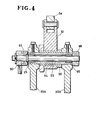
- each of the parts feeders 18, 19 includes a hopper 73 fixedly mounted on a support arm 74 projecting from the frame 20 laterally upwardly at an oblique angle, and a rotary drum 75 rotatably mounted on the hopper 73.
- the hopper 73 includes an upper inlet opening 76 through which corresponding ones of the fastener elements A, B are supplied into the hopper 73, and a cover or lid 77 hinged to the hopper 73 to open and close the inlet opening 76.
- the rotary drum 75 is keyed for corotation to a drive shaft 78 which is rotatably mounted on a central boss 79 of the hopper 73 by means of a pair of ball bearings 80.
- the rotary drum 75 has a flared inner peripheral edge portion 81 received in a horizontal circular opening 82 provided in a sidewall 83 of the hopper 73.
- the peripheral edge portion 81 has a plurality of circumferentially spaced recesses 84 spaced at equal intervals and facing the hopper 73.
- the hopper 73 has a guide groove 85 extending outwardly along the peripheral edge portion 81.
- Each of the recesses 84 receives a portion of a respective one of the fastener element A, B and the groove 85 guides a different portion of the thus received fastener element A, B.
- the chute 42 has a longitudinal guide track 86 communicated at opposite ends with the guide groove 85 of the parts feeder 18 and the guide channel 41 of the loading unit 14.
- the chute 47 has a guide track 87 communicated at opposite ends with the guide groove 85 of the parts feeder 19 ( Figure 2) and the guide channel 46 of the loading unit 15.
- the second drive mechanism 17 comprises a fluid-actuated cylinder 88 pivotably mounted on the frame 20 by means of a pin 89, and a first rocking lever 90 rockingly mounted on the frame 20 and having a free end pivoted to one end of a connector rod 91, the other end of the connector rod 91 being secured to a piston rod 92 of the cylinder 88.
- the first rocking lever 90 is mounted on a solid shaft 93 rotatably mounted in a concentric hollow shaft 94 by means of a pair of roller bearings 95.
- the lollow shaft 93 is secured at opposite ends to a pair of laterally spaced vertical supports 20a, 20b of the frame 20.
- the rocking lever 51 of the first drive mechanism 16 is pivotably mounted on the hollow shaft 94 by means of a sleeve bearing 96 disposed between the supports 20a, 20b.
- a pair of second rocking levers 97, 98 is disposed on the outside of the respective supports 20a, 20b and they are secured to the shaft 93 for corotation therewith, one of the levers 97 being held in driven engagement with the first rocking lever 90.
- the rocking levers 97, 98 are connected respectively with a pair of third rocking levers 99, 100 via respective connecting rods 101,'102.
- Each of the rocking levers 99, 100 is mounted on a corresponding one of the drive shafts 78 via a one-way clutch 103.
- the cylinder 88 of the second drive mechanism 17 is smaller in size and power than the cylinder 49 of the first drive mechanism 16. More specifically, the cylinder 88 is so constructed as to exert a drive force to an extent that it comes to halt when the fastener elements A, B are jammed in either parts feeder 16, 17.
- the apparatus 10 operates as follows: The cylinder 49 of the first drive mechanism 16 is actuated to extend its piston rod 52 whereupon the toggle joint 56 extends its levers 57, 58 as indicated by phantom lines in Figure 1, thereby clinching the fastener elements A, B between the punch 36 and the die. At the same time, the forward movement of the piston rod 52 causes the levers 63, 66 to pivot about the shaft 64 in the counterclockwise direction in Figure 1, thereby bringing the pusher bars 63, 65 from respective advanced positions to respective retracted positions indicated by phantom lines in this figure. Then, one fastener element A is supplied from the parts feeder 18 through the chute 42 into the guide channel 41 in the guide block 40 of the first loading unit 14.
- the cylinder 88 of the second drive mechanism 17 is actuated in timed relation to the cylinder 49 and hence to the reciprocation of the punch 36 such that the fastener elements A, B are supplied to the respective loading units-14, 15 while the pusher bars 43, 45 are held in the respective retracted positions as described above.
Landscapes
- Engineering & Computer Science (AREA)
- Mechanical Engineering (AREA)
- Textile Engineering (AREA)
- Slide Fasteners (AREA)
- Press Drives And Press Lines (AREA)
- Automatic Assembly (AREA)
Applications Claiming Priority (2)
| Application Number | Priority Date | Filing Date | Title |
|---|---|---|---|
| JP180594/83U | 1983-11-22 | ||
| JP18059483U JPS6089225U (ja) | 1983-11-22 | 1983-11-22 | 釦加工装置 |
Publications (1)
| Publication Number | Publication Date |
|---|---|
| EP0142853A2 true EP0142853A2 (de) | 1985-05-29 |
Family
ID=16085989
Family Applications (1)
| Application Number | Title | Priority Date | Filing Date |
|---|---|---|---|
| EP19840114003 Withdrawn EP0142853A2 (de) | 1983-11-22 | 1984-11-20 | Vorrichtung zum Zusammensetzen von Knöpfen |
Country Status (5)
| Country | Link |
|---|---|
| EP (1) | EP0142853A2 (de) |
| JP (1) | JPS6089225U (de) |
| AU (1) | AU3516884A (de) |
| ES (1) | ES537853A0 (de) |
| GB (1) | GB2150068A (de) |
Cited By (4)
| Publication number | Priority date | Publication date | Assignee | Title |
|---|---|---|---|---|
| EP0345622A3 (de) * | 1988-06-04 | 1991-02-27 | Schaeffer GmbH | Maschine zum Ansetzen von Knöpfen, Nieten oder dergleichen, vorzugsweise an Bekleidungsstücke |
| CN105033097A (zh) * | 2015-08-20 | 2015-11-11 | 石狮市龙翔五金塑料制品有限公司 | 一种自动铆扣机 |
| CN105436349A (zh) * | 2015-12-29 | 2016-03-30 | 宏基钮扣(石狮)有限公司 | 一种多用纽扣用铆合机 |
| CN109622781A (zh) * | 2019-01-17 | 2019-04-16 | 浙江炬达机械有限公司 | 自动钉扣机 |
Family Cites Families (1)
| Publication number | Priority date | Publication date | Assignee | Title |
|---|---|---|---|---|
| JPS5125775A (ja) * | 1974-08-27 | 1976-03-02 | Tokyo Shibaura Electric Co | Gasushadanki |
-
1983
- 1983-11-22 JP JP18059483U patent/JPS6089225U/ja active Pending
-
1984
- 1984-11-07 AU AU35168/84A patent/AU3516884A/en not_active Abandoned
- 1984-11-12 GB GB08428573A patent/GB2150068A/en not_active Withdrawn
- 1984-11-20 EP EP19840114003 patent/EP0142853A2/de not_active Withdrawn
- 1984-11-22 ES ES84537853A patent/ES537853A0/es active Granted
Cited By (7)
| Publication number | Priority date | Publication date | Assignee | Title |
|---|---|---|---|---|
| EP0345622A3 (de) * | 1988-06-04 | 1991-02-27 | Schaeffer GmbH | Maschine zum Ansetzen von Knöpfen, Nieten oder dergleichen, vorzugsweise an Bekleidungsstücke |
| CN105033097A (zh) * | 2015-08-20 | 2015-11-11 | 石狮市龙翔五金塑料制品有限公司 | 一种自动铆扣机 |
| CN105033097B (zh) * | 2015-08-20 | 2017-02-01 | 石狮市龙翔五金塑料制品有限公司 | 一种自动铆扣机 |
| CN105436349A (zh) * | 2015-12-29 | 2016-03-30 | 宏基钮扣(石狮)有限公司 | 一种多用纽扣用铆合机 |
| CN105436349B (zh) * | 2015-12-29 | 2017-07-04 | 宏基钮扣(石狮)有限公司 | 一种多用纽扣用铆合机 |
| CN109622781A (zh) * | 2019-01-17 | 2019-04-16 | 浙江炬达机械有限公司 | 自动钉扣机 |
| CN109622781B (zh) * | 2019-01-17 | 2024-04-16 | 浙江炬达机械有限公司 | 自动钉扣机 |
Also Published As
| Publication number | Publication date |
|---|---|
| ES8506990A1 (es) | 1985-09-01 |
| AU3516884A (en) | 1985-05-30 |
| GB2150068A (en) | 1985-06-26 |
| ES537853A0 (es) | 1985-09-01 |
| JPS6089225U (ja) | 1985-06-19 |
| GB8428573D0 (en) | 1984-12-19 |
Similar Documents
| Publication | Publication Date | Title |
|---|---|---|
| AU699299B2 (en) | Rivet feed apparatus | |
| EP0633826A4 (de) | Modulare stanzstation und verfahren zur anwendung. | |
| NZ197560A (en) | Mounting rivets in a flexible carrier | |
| DE3822519A1 (de) | Vorrichtung zum winkelgerechten positionieren eines hart-kurzwaren-artikels, wie eines knopfes od. dgl., im werkzeug einer ansetzmaschine | |
| US4122988A (en) | Pierce rivet machine | |
| US4895013A (en) | Workpiece transfer apparatus for a punch press | |
| EP0142853A2 (de) | Vorrichtung zum Zusammensetzen von Knöpfen | |
| EP0749802A1 (de) | Vorrichtung für die schrittweise Speisung und die automatische Befestigung von selbststanzenden Elementen | |
| EP0131180B1 (de) | Maschine zum Ansetzen von Knöpfen | |
| US4959988A (en) | Applicator die | |
| CN218983055U (zh) | 冲孔铆合切换装置以及铆合机 | |
| US2647552A (en) | Punch press | |
| US4307511A (en) | Apparatus for attaching an end stop to a slide fastener stringer | |
| US3266132A (en) | Multiple part assembly machine | |
| US4479290A (en) | Space forming and stop fixing apparatus for fastener chains | |
| US5323919A (en) | Button feeder for button applicator | |
| KR870000711B1 (ko) | 분리가능한 슬라이드 파스너 체인 절단장치 및 그 방법 | |
| US2953275A (en) | Envelop fastener machine | |
| US4839963A (en) | Slider handling apparatus | |
| US4434928A (en) | Tape feeding device for stapling machines | |
| US4549348A (en) | Apparatus for securing bottom end stop to fastener chain | |
| EP0213599B1 (de) | Vorrichtung zum Anbringen von oberen Endgliedern an einer fortlaufenden Reissverschlusskette | |
| KR940000182A (ko) | 가구용 못의 제조장치 | |
| JPS5911681B2 (ja) | 釦自動取付装置 | |
| US2804621A (en) | Clip-forming and clinching mechanisms |
Legal Events
| Date | Code | Title | Description |
|---|---|---|---|
| PUAI | Public reference made under article 153(3) epc to a published international application that has entered the european phase |
Free format text: ORIGINAL CODE: 0009012 |
|
| AK | Designated contracting states |
Designated state(s): BE CH DE FR IT LI NL SE |
|
| STAA | Information on the status of an ep patent application or granted ep patent |
Free format text: STATUS: THE APPLICATION HAS BEEN WITHDRAWN |
|
| 18W | Application withdrawn |
Withdrawal date: 19851010 |
|
| RIN1 | Information on inventor provided before grant (corrected) |
Inventor name: SODENO, TOSHIAKI |