EP0142844A2 - Vehicle wheel with emergency running support - Google Patents
Vehicle wheel with emergency running support Download PDFInfo
- Publication number
- EP0142844A2 EP0142844A2 EP84113948A EP84113948A EP0142844A2 EP 0142844 A2 EP0142844 A2 EP 0142844A2 EP 84113948 A EP84113948 A EP 84113948A EP 84113948 A EP84113948 A EP 84113948A EP 0142844 A2 EP0142844 A2 EP 0142844A2
- Authority
- EP
- European Patent Office
- Prior art keywords
- rim
- tire
- vehicle wheel
- wheel according
- support
- Prior art date
- Legal status (The legal status is an assumption and is not a legal conclusion. Google has not performed a legal analysis and makes no representation as to the accuracy of the status listed.)
- Granted
Links
Images
Classifications
-
- B—PERFORMING OPERATIONS; TRANSPORTING
- B60—VEHICLES IN GENERAL
- B60C—VEHICLE TYRES; TYRE INFLATION; TYRE CHANGING; CONNECTING VALVES TO INFLATABLE ELASTIC BODIES IN GENERAL; DEVICES OR ARRANGEMENTS RELATED TO TYRES
- B60C17/00—Tyres characterised by means enabling restricted operation in damaged or deflated condition; Accessories therefor
- B60C17/04—Tyres characterised by means enabling restricted operation in damaged or deflated condition; Accessories therefor utilising additional non-inflatable supports which become load-supporting in emergency
-
- B—PERFORMING OPERATIONS; TRANSPORTING
- B60—VEHICLES IN GENERAL
- B60B—VEHICLE WHEELS; CASTORS; AXLES FOR WHEELS OR CASTORS; INCREASING WHEEL ADHESION
- B60B21/00—Rims
- B60B21/12—Appurtenances, e.g. lining bands
-
- B—PERFORMING OPERATIONS; TRANSPORTING
- B60—VEHICLES IN GENERAL
- B60C—VEHICLE TYRES; TYRE INFLATION; TYRE CHANGING; CONNECTING VALVES TO INFLATABLE ELASTIC BODIES IN GENERAL; DEVICES OR ARRANGEMENTS RELATED TO TYRES
- B60C17/00—Tyres characterised by means enabling restricted operation in damaged or deflated condition; Accessories therefor
- B60C17/10—Internal lubrication
Definitions
- the width of the emergency run support 16 is B M , the diameter is DM, the radius of the arched support surface is RM and the radius of the lateral curve is R.
- the radial height of the emergency run support, measured over the rim flange, is designated with HM. The following structural and design parameters are important for the arrangement and design of the emergency run support and assignment to the wheel rim.
- the width B R of the annulus is about 1.5 times wider than the tire bead 12 in the width B ß .
Abstract
Description
Die Erfindung bezieht sich auf ein Luftreifen-Fahrzeugrad, das im wesentlichen aus einer zum Zwecke des Ein- und Ausbaues des Luftreifens nicht teilbar ausgebildeten, einer insoweit einteiligen Radfelge und aus einem Luftreifen in Standardausbildung besteht, und die Radfelge zusätzlich eine Notlaufstütze aufweist.The invention relates to a pneumatic tire vehicle wheel, which consists essentially of a non-divisible for the purpose of installing and removing the pneumatic tire, a one-piece wheel rim and a pneumatic tire of standard design, and the wheel rim additionally has an emergency run support.
Der Standard-Luftreifen wird gebildet aus einer Karkasse, insbesondere einer Radialkarkasse, mit zwei im Seitenabstand zueinander angeordneten, zugfeste Wulstkerne enthaltenden Reifenwülsten, daran sich anschließenden Seitenwänden und einem zentralen Laufstreifen, insbesondere einem gürtelverstärkten, Laufprofil aufweisenden Laufstreifen.The standard pneumatic tire is formed from a carcass, in particular a radial carcass, with two tire beads, spaced apart from one another, containing tensile bead cores, adjoining side walls and a central tread, in particular a belt-reinforced tread with tread.
Die Radfelge wird gebildet aus zwei im Seitenabstand zueinander angeordneten Felgenschultern, die axial innen geneigt verlaufen und durch ein vertieftes Felgenbett miteinander verbunden sind und axial außen in je einen Felgenrand oder ein Felgenhorn übergehen. Hierbei handelt es sich um eine Standardfelge mit üblichen genormten Abmessungen.The wheel rim is formed from two rim shoulders which are arranged at a lateral distance from one another and which are inclined axially on the inside and are connected to one another by a recessed rim bed and merge axially on the outside into a rim rim or a rim flange. This is a standard rim with the usual standardized dimensions.
In dem vertieften Felgenbett ist zusätzlich eine Notlaufstütze angeordnet, die aus einem Fußteil und einem Reifenstützteil besteht. Der Fußteil ist mit der Radfelge fest verbunden und zum Zwecke des Reifenein- und Ausbaues nicht lösbar angeordnet. Der Reifenstützteil wird von einer (im Querschnitt betrachtet) bevorzugt pilzförmigen radialen Verlängerung des Fußteils gebildet. Er ragt um ein bestimmtes, wählbares Maß über das Felgenhorn radial hinaus. Er dient im Notlauffall als lasttragendes Element und ist, zur bestmöglichen Reifenabstützung und um Schäden am luftleeren Reifen zu vermeiden, so breit wie möglich auszubilden.An emergency run support is additionally arranged in the recessed rim well, which consists of a foot part and a tire support part. The foot section is firmly connected to the wheel rim and is not detachably arranged for the purpose of tire installation and removal. The tire support part is formed by a preferably mushroom-shaped radial extension of the foot part (viewed in cross section). It protrudes radially beyond the rim flange by a certain, selectable dimension. In the event of an emergency, it serves as a load-bearing element and, in order to provide the best possible tire support and to avoid damage to the deflated tire, it must be designed as wide as possible.
Bei derartigen Fahrzeugrädern werden die Reifenwülste von den Felgenhörnern auf der Radfelge gehalten, damit diese nicht seitlich von der Radfelge abrutschen können. Des weiteren kann mindestens eine Felgenschulter mit einem Sicherheitsbuckelrand (Hump) versehen sein, der den Reifenwulst daran hindert, daß er von der Felgenschulter in das Tiefbett abrutschen kann. Das Tiefbett ist ein bewährtes Hilfsmittel, um den Ein- und Ausbau des Luftreifens zu erleichtern.In such vehicle wheels, the tire beads are held on the wheel rim by the rim flanges, so that they cannot slide off the side of the wheel rim. Furthermore, at least one rim shoulder can be provided with a safety hump edge, which prevents the tire bead from slipping off the rim shoulder into the drop center. The low bed is a tried and tested tool to make it easier to install and remove the pneumatic tire.
Die bekannten Fahrzeugräder, deren Radfelge mit einer Notlaufstütze versehen sind, die im Notlauffall den Luftreifen stützen, weisen in mehrfacher Hinsicht wesentliche Nachteile auf.The known vehicle wheels, whose wheel rims are provided with an emergency run support, which support the pneumatic tire in the event of an emergency run, have significant disadvantages in several respects.
Zum einen kann ein Felgentiefbett seine Funktion als Ein- und Ausbauhilfe für den Luftreifen dann nicht erfüllen, wenn das Tiefbett im wesentlichen von der Notlaufstütze ausgefüllt wird. Dies ist gleichzusetzen mit einem fehlenden Tiefbett, durch das die Reifenmontage sehr erschwert bis unmöglich ist.On the one hand, a deep rim bed cannot fulfill its function as an installation and removal aid for the pneumatic tire if the deep bed is essentially filled by the emergency run support. This is equivalent to a lack of a low bed, which makes tire assembly very difficult or even impossible.
. Zum anderen sind bekannte NotlaufstUtzen aus Gründen der günstigen Reifenmontage mit einer verhältnismäßig schmalen Reifenstützfläche ausgestattet. Ein luftleerer Luftreifen wird hierdurch sehr unvollkommen abgestützt und die Gefahr, daß die gewölbten Seitenwände bei Notlauf Bodenkontakt haben und auf Grund hoher Reibung zerstört werden, ist hierdurch sehr groß. Bekannte Notlaufstützen mit breiter Stützfläche behindern wiederum die Reifenmontage, weil dazu der erforderliche Freiraum fehlt.. On the other hand, known emergency running supports are equipped with a relatively narrow tire support surface for reasons of cheap tire assembly. An air-deflated pneumatic tire is thereby very imperfectly supported and the risk that the curved side walls come into contact with the ground during emergency running and are destroyed due to high friction is very great. Known emergency run supports with a wide support surface in turn hinder tire mounting because the required space is not available.
Die Notlaufstütze ist auf Grund ihrer Ausbildung und Anordnung geeignet, Last im Notlauffall aufzunehmen. Sie wird jedoch dem häufig auftretenden, unter Umständen sehr gefährlichen Betriebszustand des Luftreifens nicht gerecht, der durch häufigen geringen Druckluftverlust entsteht. Dies kann z.B. bei häufigen Kurvenfahrten mit überhöhter Geschwindigkeit, höherer Diffusion oder durch Sitzuhgenauigkeit als Folgeursache durch Auffahren auf Bordsteinkanten oder ähnlichen Einwirkungen der Fall sein.Due to its design and arrangement, the emergency run support is suitable for lifting loads in an emergency. However, it does not do justice to the frequently occurring and possibly very dangerous operating condition of the pneumatic tire, which is caused by frequent, low loss of compressed air. This can e.g. in the case of frequent cornering with excessive speed, higher diffusion or due to seating accuracy as a result of collision with curbs or similar effects.
Bei den sich dabei auf Dauer einstellenden Minderluftdrücken besteht die Gefahr, daß der Luftreifen von der Radfelge abspringt. Dies ist stets mit einer hohen Unfallgefahr durch das außer Kontrolle geratende Fahrzeug verbunden. Dieser Betriebszustand ist deshalb so gefährlich, weil er durch mangelnde regelmäßige Überprüfung des Reifenluftdruckes seitens des Fahrzeugfahrers nicht erkannt wird.Given the permanent low air pressure there is a risk that the pneumatic tire will jump off the wheel rim. This is always associated with a high risk of accidents caused by the vehicle getting out of control. This operating state is so dangerous because it is not recognized by the vehicle driver due to a lack of regular checking of the tire air pressure.
Hier ist ein geeignetes einfaches Mittel erforderlich, das den Betriebszustand des Abspringens des Luftreifens von der Radfelge zuverlässig verhindert.A suitable simple means is required here that reliably prevents the pneumatic tire from jumping off the wheel rim.
Ziel der Erfindung ist es, sowohl den luftarmen als auch den luftleeren Luftreifen sicher zu halten und zu stützen, das Abrutschen von der Radfelge zu verhindern und einen bestmöglichen Notlauf zu gewährleisten, ohne daß der Reifen oder die Felge dabei zerstört werden. Der Ein- und Ausbau des Luftreifens soll mit Hilfe einer zu diesem Zweck nicht teilbaren Radfelge, ähnlich wie bei Standardfelgen ohne Notlaufstütze erleichtert, ermöglicht werden, ohne daß dabei auf eine verhältnismäßig breite Stützfläche an der Notlaufstütze verzichtet und daß ein vertieftes Felgenbett beibehalten wird.The aim of the invention is to hold and support both the deflated and the deflated pneumatic tire securely, to prevent slipping off the wheel rim and to ensure the best possible emergency running without the tire or the rim being destroyed in the process. The installation and removal of the pneumatic tire should be made easier with the help of a wheel rim that cannot be divided for this purpose, similar to standard rims without an emergency run support, without sacrificing a relatively wide support surface on the run-flat support and without maintaining a recessed rim base.
Die technische Aufgabe der Erfindung besteht darin, das Luftreifen-Fahrzeugrad mit Notlaufstütze nach der eingangs beschriebenen Gattung so weiterauszubilden, daß die Notlaufstütze zusätzlich zur Notlauftragfähigkeit auch zum Sichern gegen Abwurf der Reifenwülste von der Radfelge und zusätzlich zum Aufnehmen der Reifenwülste beim Ein-und Ausbau sowie Notlauf des Luftreifens ausgebildet und einfach und günstig der Radfelge zugeordnet werden soll, wobei ein erleichterter Ein- und Ausbau sowie eine zuverlässige Notlaufabstützung des Luftreifens durch Beibehalten eines vertieften Felgenbettes und einer möglichst breiten Stützfläche der Notlaufstütze gewährleistet sein sollen.The technical object of the invention is to develop the pneumatic tire vehicle wheel with an emergency run support according to the type described at the outset in such a way that the emergency run support, in addition to the emergency running load-bearing capacity, also for securing against dropping of the tire beads from the wheel rim and additionally for receiving the tire beads during installation and removal as well Emergency running of the pneumatic tire should be designed and assigned to the wheel rim easily and inexpensively, whereby an easier installation and removal as well as reliable emergency running support of the pneumatic tire should be ensured by maintaining a recessed rim well and the largest possible support surface of the emergency running support.
Erfindungsgemäß wird diese Aufgabe dadurch gelöst, daß an einer breiten Notlaufstütze eine radial innere, der Felgenschulter zugewandte Fläche ausgebildet ist, die in einem bestimmten, jedoch wählbaren Abstand zur Felgenschulter vorliegt und mindestens etwa der Reifenwulstdicke entsprechend groß bemessen ist und einen begrenzten Durchlaß zum vertieften Felgenbett bildet, und daß an der Notlaufstütze des weiteren ein radial nach innen bis zum vertieften Felgenbettreichender, axial nach innen erweiterter Ringraum ausgebildet ist, der als den Reifenwulst aufnehmender Raum vorliegt, der vom Felgenbett und von der eingeschnürten Innenkontur der Notlaufstütze begrenzt ist.According to the invention this object is achieved in that a radially inner surface facing the rim shoulder is formed on a wide emergency running support, which is at a certain but selectable distance from the rim shoulder and is dimensioned at least approximately as large as the bead thickness and has a limited passage to the recessed rim base forms, and that on the emergency run support a radially inward to the recessed rim bed, axially inward widened annular space is formed, which is present as the tire bead receiving space, which is limited by the rim well and the constricted inner contour of the emergency run support.
Auf einfache Weise werden somit günstig sowohl ein Durchlaß als auch ein Freiraum für den Reifenwulst geschaffen, die einen erleichterten Ein- und Ausbau und eine angemessene Bewegungsfreiheit des Luftreifens ermöglichen. Bei Betriebszustand des Luftreifens mit Minderluftdruck bildet die radial innere Fläche an der Notlaufstütze eine Art Anlauffläche, durch deren Widerstand verhindert wird, daß der luftarme Luftreifen von der Radfelge abspringen kann. Bei größerem Druckluftverlust kann der Reifenwulst zwar durch die gebildete Engstelle zwischen Felgenschulter und Notlaufstütze in Richtung auf den freien Ringraum ausweichen. Er wird jedoch bei der Rückbewegung durch den Durchlaß auch in diesem Fall daran gehindert, von der Radfelge abzuspringen. Bei luftleerem Luftreifen wird der Reifenwulst entweder im Durchlaß oder im freien Ringraum mit genügender Bewegungsfreiheit aufgenommen, so daß der zentrale Reifenteil günstig breit und sicher von der Notlaufstützfläche getragen wird, ohne daß Teile des Reifens oder der Felge bei Notlauf mit ausreichender Notlaufgeschwindigkeit auf und ausreichender Fahrstrecke Schaden nehmen.In a simple manner, both a passage and a free space for the tire bead are thus inexpensively created, which enable easier installation and removal and adequate freedom of movement of the pneumatic tire. When the pneumatic tire is operating with low air pressure, the radially inner surface on the emergency run support forms a kind of contact surface, the resistance of which prevents the pneumatic tire from jumping off the wheel rim. If there is a greater loss of compressed air, the tire bead can deflect towards the free annular space through the constriction formed between the rim shoulder and the emergency run support. However, it is also prevented from jumping off the wheel rim during the return movement through the passage. In the case of a deflated pneumatic tire, the tire bead is received either in the passage or in the free annular space with sufficient freedom of movement so that the central tire part is carried cheaply broadly and safely by the run-flat support surface, without parts of the tire or the rim running in run-flat fashion with sufficient run-flat speed and a sufficient driving distance Get damaged.
Die Kombination der Merkmale der möglichst breiten Notlaufstütze mit radial innerer Fläche als Anlaufwiderstand, des zusammen mit der im wählbaren Abstand vorliegenden Felgenschulter gebildeten Durchlasses und des zusammen mit dem vertieften Felgenbett gebildeten freien Ringraumes schaffen ein Fahrzeugrad, das als Sicherheitsrad dient, das den luftarmen wie den luftleeren Luftreifen gleichermaßen zuverlässig auf der Radfelge hält und stützt, das wie ein übliches Fahrzeugrad, bestehend aus Reifen und Felge nach Standard, trotz der Notlauf stütze günstig und einfach im Aufbau, ohne Schwierigkeiten zu handhaben und verhältnismäßig kostengünstig ist.The combination of the features of the widest possible emergency run support with a radially inner surface as starting resistance, the passage formed together with the rim shoulder available at a selectable distance and the free annular space formed together with the recessed rim bed create a vehicle wheel that serves as a safety wheel that protects both the low-air and the low-air empty air tire holds and supports equally reliably on the wheel rim, which like a conventional vehicle wheel, consisting of tires and rims according to standard, despite the emergency running support, is inexpensive and simple in construction, without difficulties to handle and is relatively inexpensive.
Bevorzugt befindet sich die Durchlaß mitbildende Fläche an einer bestimmten, jedoch wählbaren Stelle der Innenkontur der Notlaufstütze, die Punkt einer Kurve ist, die etwa parallel zu einer gedachten Linie zwischen dem Innenrand der Felgenschulter bzw. Innenkontur des Sicherheitsbuckelrandes (Hump) und dem Felgenhorn verläuft und die des weiteren nach radial außen etwa parallel zu der Reifenaußenkontur verläuft. Auf diese Weise kann abhängig von der Reifen- und Felgengröße die günstigste Innenfläche ausgebildet werden.The passage-forming surface is preferably located at a specific, but selectable point on the inner contour of the emergency run support, which is the point of a curve which runs approximately parallel to an imaginary line between the inner edge of the rim shoulder or inner contour of the safety hump edge (Hump) and the rim flange and which also runs radially outward approximately parallel to the outer contour of the tire. In this way, the cheapest inner surface can be formed depending on the tire and rim size.
Die Innenfläche kann eine geradlinig begrenzte, insbesondere konische Fläche, sie kann aber auch eine bogenlinig begrenzte, insbesondere im Bereich des seitlichen Randes der Notlaufstütze gerundete Fläche sein. Die große Breite der Notlaufstütze begünstigt die Lage der Anlauffläche als Widerstandsfläche gegen Abwurf.The inner surface can be a rectilinearly delimited, in particular conical, surface, but it can also be an arcuately delimited, in particular in the area of the lateral edge of the emergency running support. The large width of the emergency support supports the position of the contact surface as a resistance surface against dropping.
Form und Lage der Fläche richten sich nach Größe und Form der Notlaufstütze. Für PKW-Felgen kann sie unterschiedlich zu LKW- bzw. Motorradfelgen sein. Bevorzugt sind Anlauffläche und Ringraum beidseitig an der Notlaufstütze ausgebildet.The shape and position of the surface depend on the size and shape of the emergency support. For car rims, it can be different from truck or motorcycle rims. The contact surface and the annular space are preferably formed on both sides of the emergency run support.
Der lichte Abstand (BF) zwischen der Fläche an der Notlaufstütze und der Felgenschulter beträgt bevorzugt das 1,1 bis 2fache der Reifenwulstdicke (BB) des jeweils verwendeten Reifens in der jeweiligen Größe. Er kann bis zur 3fachen Wulstdicke vergrößert vorliegen, wenn die Reifengröße dies erfordert.The clear distance (B F ) between the surface on the emergency run support and the rim shoulder is preferably 1.1 to 2 times the tire bead thickness (B B ) of the tire used in the respective size. It can be enlarged up to 3 times the bead thickness if the tire size so requires.
Die neuen Ausbildungen der Fläche und des Ringraumes an der Notlaufstütze haben Einfluß auf die radiale Vertiefung des Felgenbettes. Diese kann eine Höhe von nur dem 0,3fachen der Höhe eines Standardtiefbettes aufweisen und erfüllt dennoch zuverlässig die Funktionen der Montagevertiefung wie auch der sicheren Wulstaufnahme bei Notlauf. Die Tiefe des Felgenbettes darf nicht größer sein als die jeweils vorhandene Höhe des Felgenhornes. In diesem Falle konnte unter ungUnstigen Bedingungen ein Reifenabwurf möglich sein.The new designs of the surface and the annular space on the emergency run support have an impact on the radial depression of the rim well. This can have a height of only 0.3 times the height of a standard drop bed and still reliably fulfills the functions of the mounting recess as well as the safe bead mounting in emergency operation. The depth of the rim well must not be greater than the height of the rim flange. In this case, it could be possible to drop the tires under unfavorable conditions.
Bevorzugt ist der Querschnitt der im wesentlichen ringartigen Notlaufstütze pilzförmig oder T-förmig ausgebildet. Sie kann integriertes Teil einer einteiligen Radfelge oder getrenntes Bauteil sein, das fest mit der Radfelge verbindbar ist. Ein solches Bauteil kann nachträglich auf Radfelgen mit Tiefbett übernommen werden. Wesentliche Voraussetzungen sind breite Stützfläche, Anlaufflächenkontur radial innen und schmale, jedoch ausreichende Fußteilbreite der Notlaufstütze, die sich zum Verbinden mit der Tiefbettfelge eignet.The cross section of the essentially ring-like emergency running support is preferably mushroom-shaped or T-shaped. It can be an integrated part of a one-piece wheel rim or a separate component that can be firmly connected to the wheel rim. Such a component can be subsequently taken over on wheel rims with a drop center. Essential requirements are a wide support surface, radial contact surface contour and narrow, but sufficient foot section width of the emergency run support, which is suitable for connection to the drop center rim.
Die Notlaufstütze kann aus metallischen oder zumindest teilweise metallischen Werkstoffen gebildet sein. Es können jedoch auch formfeste, beanspruchungssichere Nichtmetalle, wie z.B. Kunststoffe oder Kunstharze, eingesetzt werden. Zur verbesserten Luftvolumenausnutzung des Reifens kann eine hohl ausgebildete Notlaufstütze mit Durchbrüchen versehen sein. Dies hat auch Vorteile hinsichtlich eines geringen Gewichtes.The emergency run support can be formed from metallic or at least partially metallic materials. However, dimensionally stable, stress-proof non-metals such as e.g. Plastics or synthetic resins are used. To improve the tire's air volume utilization, a hollow emergency run support can be provided with openings. This also has advantages in terms of low weight.
Die Notlaufstütze kann, wie es an sich bekannt ist, mit einem besonderen Stützflächenbelag versehen oder der Stützteil aus einem solchen gebildet sein. Neu ist, daß die Notlaufstütze wahlweise mit einem hohe oder niedrige Reibung erzeugenden Werkstoff versehen sein kann. Das richtet sich danach, ob es sich um ein Fahrzeugrad an der getriebenen oder nichtgetriebenen Achse handelt. Wenn die ReifenwUlste eines luftleeren Reifens bei Notlauf in das Tiefbett ausweichen sollen, so daß geringe Relativbewegungen zwischen Reifen und Notlaufmantel, z.B. bei einem Antriebsrad, gewünscht werden, so besteht die Kontaktfläche aus Material hoher Reibung.The emergency run support can, as is known per se, be provided with a special support surface covering or the support part can be formed from such. What is new is that the emergency run support can optionally be provided with a high or low friction material. This depends on whether it is a vehicle wheel on the driven or non-driven axle. If the tire beads of a deflated tire should run into the drop center during emergency running, so that slight relative movements between the tire and the emergency running jacket, e.g. in the case of a drive wheel, the contact surface consists of high-friction material.
Wenn die Reifenwülste auf Felgenschultern mit einem sogenannten Sicherheitsbuckelrand (Hump) solange wie möglich gehalten werden sollen, also Betriebszustand eines luftarmen Reifens vorliegt, so daß Quer- und Umfangskräfte durch die Reifenwülste zu übertragen sind, so kann die Kontaktfläche der Notlaufstütze mit Material geringer Reibung belegt sein oder ein solches, wie z.B. geeignetes Gleitmittel, auf ihr oder auf der Reifeninnenfläche aufgetragen sein. Für den Fall gewünschter Schmierung kann ein Schmiermittelbehälter bevorzugt in der hohl ausgebildeten Notlaufstütze günstig angeordnet werden.If the tire beads on rim shoulders with a so-called safety hump (hump) are to be kept as long as possible, i.e. the operating condition of a low-air tire is present so that transverse and circumferential forces are transmitted through the tire beads, the contact surface of the run-flat support can be covered with low-friction material be or such, such as suitable lubricant, be applied to it or on the inner surface of the tire. If lubrication is desired, a lubricant container can preferably be arranged favorably in the hollow emergency run support.
Die Notlaufstütze ist an der radial äußeren Stützfläche bevorzugt so breit wie möglich, etwa so breit wie das vertiefte Felgenbett ausgebildet. In weiteren Fällen kann sie auch axial verbreitert, bevorzugt bis zur 1.5fachen Breite des Tiefbettes verbreitert vorliegen. Die radiale Höhe der Notlaufstütze übertrifft das Felgenhorn mindestens um Reifenseitenwanddicke. Sie kann radial bis zur 0,7fachen Reifenhöhe betragen, abzüglich der Felgenhornhöhe. Bevorzugt weist sie jedoch eine weniger große Höhe auf. Dies ist von der Reifengröße abhängig.The emergency run support is preferably formed as wide as possible on the radially outer support surface, approximately as wide as the recessed rim base. In other cases, it can also be axially widened, preferably widened up to 1.5 times the width of the deep bed. The radial height of the emergency run support exceeds the rim flange by at least the tire sidewall thickness. It can be radial up to 0.7 times the tire height, minus the rim flange height. However, it preferably has a less large height. This depends on the tire size.
Weitere Erfindungsmerkmale und Einzelheiten des Luftreifen-Fahrzeugrades sind in der Zeichnung dargestellt und an Hand von Ausführungsbeispielen erläutert.Further features of the invention and details of the pneumatic vehicle wheel are shown in the drawing and explained using exemplary embodiments.
Es zeigt
- Fig. 1 ein Luftreifen-Fahrzeugrad mit Notlaufstütze im Querschnitt,
- Fig. 2 eine Prinzipskizze eines Fahrzeugrades mit Radfelge, Notlaufstütze und Reifenwülsten im Querschnitt,
- Fig. 3 eine Schema-Skizze eines Radfelgenteils und Kurvenpunkte für die Lage einer inneren Notlaufstützenfläche,
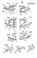
- Fig. 4 einen Teilquerschnitt durch eine Radfelge mit Notlaufstütze in einteiliger Bauweise,
- Fig. 5 einen Teilquerschnitt durch eine Radfelge mit abgewandelter Notlaufstütze in Verbundbauweise,
- Fig. 6. einen Teilquerschnitt durch eine Sicherheitsradfelge mit seitlich offener Notlaufstütze,
- Fig. 7 einen Teilquerschnitt durch eine Sicherheitsradfelge mit Notlaufstütze in Blockringbauart,
- Fig. 8 einen Teilquerschnitt durch eine weitere Sicherheitsradfelge mit abgewandelter Notlaufstütze in T-Querschnitt,
- Fig. 9 einen Teilquerschnitt durch eine weitere Sicherheitsradfelge mit weiter abgewandelter NotlaufstUtze und seitlicher Verlängerung,
- Fig. 10a-c verschiedene Reifenwülste mit unterschiedlichen Wulstneigungen und verschiedene Radfelgen in schematischen Ausschnitten.
- 1 is a pneumatic tire vehicle wheel with emergency run support in cross section,
- 2 is a schematic diagram of a vehicle wheel with wheel rim, emergency run support and tire beads in cross section,
- 3 shows a schematic sketch of a wheel rim part and curve points for the position of an inner emergency running support surface,
- 4 shows a partial cross section through a wheel rim with emergency run support in one-piece construction,
- 5 is a partial cross section through a wheel rim with modified emergency running support in composite construction,
- 6 shows a partial cross section through a safety wheel rim with an open-side emergency running support,
- 7 shows a partial cross section through a safety wheel rim with an emergency running support in a block ring design,
- 8 shows a partial cross section through a further safety wheel rim with a modified emergency run support in a T cross section,
- 9 shows a partial cross section through a further safety wheel rim with a further modified emergency running support and a lateral extension,
- 10a-c different tire beads with different bead inclinations and different wheel rims in schematic sections.
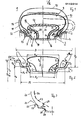
Das Luftreifen-Fahrzeugrad 1 gemäß Fig. 1 besteht im wesentlichen aus einer einteiligen Radfelge 3 und einem Luftreifen 10 und ist zusätzlich mit einer Notlaufstütze 16 ausgestattet. Es besteht aus einer üblichen, genormten Radfelge und einem üblichen Luftreifen. Es wird montiert, indem die Radfelge quer in den Luftreifen eingebracht wird.The pneumatic
Die Radfelge besteht im wesentlichen aus den beiden Felgenschultern 4 und den jeweiligen Felgenhörnern 5 sowie einem zentralen, radial vertieften Felgenbett 6. Dieses Felgenbett kann übliche genormte Abmessungen aufweisen, es kann jedoch eine radial geringere Bettiefe als das genormte Felgenbett ausweisen. Es kann auch breiter ausgeführt werden im Vergleich zum genormten Felgenbett. Die Radfelge 3 ist aufgrund ihrer Ausbildung in der Lage, die Notlaufstütze 16 in sich aufzunehmen. Beide Elemente können zu einer einteiligen oder festen, nur für den Grundaufbau geteilten Baueinheit vereinigt werden.The wheel rim essentially consists of the two
Der Luftreifen 10 besteht aus einer Karkasse 11, insbesondere bei Bauart eines Gürtelradialrei.fens aus einer Radialkarkasse, den beiden Reifenwülsten 12 mit jeweils einem zugfesten Wulstkernring 13, den beiden Seitenwänden 14 und einem Laufstreifen 15, insbesondere bei einem Gürtelreifen durch eine Gürtelkonstruktion verstärkten Laufstreifen.The
Die Notlaufstütze 16 besteht im wesentlichen aus einem Trägerteil, dem sogenannten Stützmantel 17, auf den sich bei einem Notlauf die Reifeninnenfläche 9 des luftleeren Luftreifens 10 aufstützt, und dem Standfuß 18 oder Ständerteil, mit dem die Notlaufstütze im Bereich des vertieften Felgenbettes 6 mit der Radfelge verbunden ist oder mit ihr eine Baueinheit bildet.The
Die Notlaufstütze 16 weist des weiteren eine radial innen angeordnete, der Felgenschulter 4 zugekehrte Fläche 19 auf. Sie bildet mit der Felgenschulter 4, gegebenenfalls auch mit einem Teil des Felgenhorns eine begrenzte Engstelle mit der lichten Weite BF, den Durchlaß 7; vgl. dazu auch Fig. 2.The
Diese Weite ist etwas größer bemessen als die breiteste Stelle BB des Reifenwulstes. Die Weite beträgt bevorzugt die 1,1 bis 2 fache Breite BB des Reifenwulstes 12 an der breitesten Stelle.This width is dimensioned somewhat larger than the widest point B B of the tire bead. The width is preferably 1.1 to 2 times the width B B of the
Die Fläche 19 ist als Teil der geschaffenen Engstelle zum einen eine Art Führungsfläche für die erleichterte Reifenmontage mit Hilfe des Tiefbettes. Sie ist zum anderen ihrer Funktion nach eine Art Anlauffläche bei kritischer Fahrbetriebssituation im Falle des luftarm gewordenen Luftreifens. Sie verhindert, daß ein Reifenwulst von seinem Sitz auf der Felgenschulter abgeworfen wird. Derartige Betriebszustände ergeben sich, wenn Kurven mit erhöhter Fahrgeschwindigkeit durchfahren werden. Ein luftarmer Luftreifen ist besonders gefährlich, weil er vom Fahrer nahezu unbemerkt bleibt. Durch die neu geschaffene Anlauffläche 19 wird der Reifenwulst daran gehindert, bei einer solchen kritischen Situation von der Radfelge abzuspringen. Die weitere Funktion der Fläche 19 ist die einer Sperre gegen Abwurfbewegung des Reifenwulstes bei Notlauf auf der der Kontaktfläche gegenüberliegenden Stelle. Im Falle einer Reifenpanne, wenn der Luftreifen luftleer geworden ist, bewegen sich die Reifenwülste in den neu geschaffenen Ringraum 2, der zwischen Fußstütze 18 der Notlaufstütze und dem Felgenbett 6 der Radfelge gebildet ist. Dieser Ringraum 2, an beiden Seiten im Felgenbett ausgebildet, weist eine Form und Größe auf, die ihn in die Lage versetzen, den Reifenwulst 12 bei Notlauf insgesamt aufzunehmen. Die Fläche 19 bildet bei der Notlaufbewegung dann eine Art von Widerstand, die den Reifenwulst des Teils des Reifens ohne Bodenkontakt daran hindert, von der Radfelge abzuspringen.As part of the narrowed area created, the surface 19 is on the one hand a kind of guide surface for facilitating tire mounting with the aid of the low bed. On the other hand, in terms of its function, it is a kind of contact surface in critical driving situations in the case of a tire that has become deflated. It prevents a tire bead from being dropped from its seat on the rim shoulder. Such operating conditions arise when curves with increased driving speed be driven through. A low-air pneumatic tire is particularly dangerous because it remains almost unnoticed by the driver. The newly created contact surface 19 prevents the tire bead from jumping off the wheel rim in such a critical situation. The further function of the surface 19 is that of locking against the ejection movement of the tire bead during emergency running on the point opposite the contact surface. In the event of a flat tire, when the pneumatic tire has become deflated, the tire beads move into the newly created
Die Notlaufstütze ist im Querschnitt bevorzugt pilz- oder T-förmig ausgebildet. Ihre Stützfläche 17 ist im wesentlichen so breit wie die Breite des Felgenbettes. Die Stützflächenbreite kann konstruktiv so breit wie möglich ausgeführt werden. Dadurch ist eine günstige breite Stützfläche bei einem eventuellen Notlauffall gewährleistet. Die leichte Reifenmontierbarkeit ist wegen des frei zugänglichen Tiefbettringraums voll gewährleistet.The emergency run support is preferably mushroom-shaped or T-shaped in cross section. Your
Durch die neu ausgebildete Fläche 19 an der Notlaufstütze 16 und den freien Ringraum 2 wird das Felgenbett funktionell derart unterteilt, daß es nach wie vor für die erleichterte Reifenmontage zur Verfügung steht, im Notlauffall die Reifenwülste zum Zwecke günstiger Relativbewegungen zwischen Reifen und Felge bei Notlauf aufnehmen kann und daß es die breitestmögliche Stützflächengestaltung zuläßt. Außerdem ist gewährleistet, daß selbst bei extremen Kurvenfahrten der Reifenwulst bei Minderluftdruck nicht von der Radfelge abspringen kann.Due to the newly formed surface 19 on the
Das Fahrzeugrad 1 weist eine Radfelge 3 auf, die in den genormten bzw.standardisierten Ausführungen für PKW mit B-, C-, J-, TR-, TD-, DL-Horn und schwach geneigter Felgenschulter oder mit stärker geneigter Steilschulter für LKW oder Zweiradfahrzeuge angewandt werden kann. Das Tiefbett kann symmetrisch oder asymmetrisch angeordnet sein. Die Felge kann mit oder ohne Sicherheitsrand (Hump) versehen sein. Die Felgenschulter kann auch eine von der Norm abweichende Neigung aufweisen.The
Der Prinzipskizze gemäß Fig. 2 sind weitere Einzelheiten zu entnehmen. Die Reifenhöhe HRI gemessen von der Felgenschulter 4 bis zu der größten radialen Erstreckung des Laufstreifens 15, und Reifenbreite B, gemessen an der Stelle der Seitenwände 14 breitester axialer Erstreckung, sind wichtige Baumaße so wie die Maulbreite M der Radfelge 3, gemessen an der Stelle der breitesten axialen Erstreckung der beiden Felgenschultern 4. Das Reifenquerschnittsverhältnis Reifenhöhe HR zu Reifenquerschnitt kann für Normalquerschnitt- oder Niederquerschnittreifen vorliegen.The schematic diagram according to FIG. 2 shows further details. The tire height H RI measured from the
Die Höhe des Felgenhorns 5 ist mit HF bezeichnet, der Durchmesser ist mit DFH bezeichnet; die Felgenschulter 4 ist in der axialen Erstrekkung mit BS und im Durchmesser mit DF und die Neigung der Felgenschulter 4 ist zur Achsparallelen mit Winkel α bezeichnet. Er kann 5° oder 15°, er kann auch 4° bis 16° betragen. Die Höhe des radial vertieften Felgenbettes 6 ist mit HT und die Breite ist mit BT bezeichnet.The height of the rim flange 5 is denoted by H F , the diameter is denoted by D FH ; the
Die Breite der Notlaufstütze 16 ist mit BM, der Durchmesser ist mit DM, der Radius der gewölbten Stützfläche ist mit RM und der Radius der seitlichen Rundung ist mit R bezeichnet. Die radiale Höhe der Notlaufstütze, über das Felgenhorn gemessen, ist mit HM bezeichnet. Für die Anordnung und Ausbildung der Notlaufstütze und Zuordnung zur Radfelge sind folgende Bau- und Konstruktionsgrößen von Bedeutung.The width of the
Die Reifenwulstbreite BB ist gleich oder kleiner als Felgenschulterbreite BS einer Radfelge ohne Sicherheitsrand (Hump).The tire bead width B B is equal to or less than the rim shoulder width B S of a wheel rim without a safety rim (hump).
Die Notlaufstützenbreite BM beträgt etwa der 1,0 bis 1,5fachen Breite des Felgenbettes 6; sie kann in einigen Fällen die 0,75fache Breite aufweisen.The emergency run support width B M is approximately 1.0 to 1.5 times the width of the rim base 6; in some cases it can be 0.75 times the width.
Der radiale Oberstand HM der Notlaufstütze über Felgenhorn beträgt im Minimum Dicke bzw. doppelte Dicke einer Reifenseitenwand d und kann bis zur 0,7fachen Reifenhöhe HR betragen. Der Krümmungsradius Rm für die Stützfläche beträgt etwa 1,0 bis 15fache Maulbreite M.The radial overhang H M of the emergency run support over the rim flange is at least the thickness or double the thickness of a tire sidewall d and can be up to 0.7 times the tire height H R. The radius of curvature R m for the support surface is approximately 1.0 to 15 times the width of the mouth M.
Die Höhe HT des Felgenbettes beträgt 0,3 bis l,Ofache Höhe HF des genormten Felgenhorns 5.The height H T of the rim base is 0.3 to 1 times the height H F of the standardized rim flange 5.
Der Abstand BF zwischen der radial innen ausgebildeten Fläche 19 an der Notlaufstütze und der Felgenschulter 4, insbesondere an dessen Innenrand ohne Sicherhe.itsrand (Hump), der mit 8 bezeichnet ist, beträgt das 1,1 bis 2,Ofache der Reifenwulstdicke BB und kann bis zum 3,Ofachen der Wulstbreite BB betragen. Das richtet sich nach der Größe des Reifens und der Felge.The distance B F between the radially inner surface 19 on the emergency run support and the
Das Tiefbett ist nicht tiefer als das Felgenhorn hoch ist. Es soll dadurch verhindert werden, daß der Reifen bei einem Notlauf über das Felgenhorn abgeworfen wird, wenn auf der gegenüberliegenden Reifenseite voller Bodenkontakt vorliegt.The drop center is not lower than the rim flange is high. This is to prevent the tire from being thrown off the rim flange in an emergency run if there is full ground contact on the opposite side of the tire.
Die Lage der radial inneren Fläche 19 ist abhängig von der Größe des Reifens und der Felge und kann an einer bestimmten, jedoch wählbaren Stelle der Innenkontur 20 festgelegt werden. Wie an Hand von Fig. 3 erläutert, wird hier eine gedachte Bezugslinie 21 zugrundegelegt.The position of the radially inner surface 19 is dependent on the size of the tire and the rim and can be defined at a specific, but selectable point on the inner contour 20. As explained with reference to FIG. 3, an
Es ist die Tangente an Felgenhorn 25 und Schulterrand 26 einer Felge mit einer schwach geneigten Schulter bzw. an Felgenhorn 27 und Schulterrand 28 einer Felge mit einer stark geneigten Schulter.It is the tangent to
Diese gedachte Bezugslinie setzt sich nach radial außen oberhalb des Felgenhorns in einer gedachten Bezugslinie 22 fort, die im wesentlichen der Reifenwulst/Seitenwand-Außenkontur entspricht.This imaginary reference line continues radially outward above the rim flange in an
Parallel zu diesen Bezugslinien 21, 22 erhält man Bezugslinien 23, 24. Auf diesen befinden sich Kurvenpunkte 29, die im Abstand BF zur Felgenschulter bzw. zum Felgenhorn bzw. den Linien 21, 22 angeordnet sind. Eine von diesen kann die Stelle für die Innenfläche 19 sein. Mit grösserer Reifendimension kann der Abstand zwischen Linie 22 und 24 etwas kleiner sein als BF. Es muß letztendlich ein freier Durchgang für den Reifenwulst durch die Engstelle zwischen Fläche 19 und Felgenschulter 4 gewährleistet sein.Parallel to these
Der Ringraum 2, der sich radial und axial nach innen - von der Fläche 19 aus betrachtet - erstreckt, liegt in einer Größe und Form vor, die mindestens etwas größer ist als ein Reifenwulst.The
Die Breite BR des Ringraumes ist etwa 1,5fach breiter als der Reifenwulst 12 in der Breite Bß.The width B R of the annulus is about 1.5 times wider than the
In der radialen Tiefe erstreckt sich der Ringraum 2 bis auf das Felgenbett 6. Axial begrenzt wird der Ringraum von der Innenkontur des Steges oder Fußes 18 der Notlaufstütze und der Seitenwand bzw. Rand 7 am Obergang von Felgenschulter 4 zum Tiefbett 6.In the radial depth, the
In Fig. 1 ist ferner schematisch ein luftleerer Reifen in Notlaufbetriebsstellung (gestrichelt) dargestellt, wobei sich der Reifenwulst im Ringraum 2 befindet, die Seitenwand seitlich ausgebaucht ist und der übrige Reifenteil auf der Stützfläche 17 aufliegt.1 also schematically shows an air-deflated tire in the emergency running operating position (dashed line), the tire bead being in the
Die Fläche 19 verhindert hierbei ein Auswandern des Reifenwulstes 12 aus dem Tiefbett an der (nicht dargestellten) gegenüberliegenden Seite. Die Gestaltung der Fläche 19 kann geradlinig oder bogenförmig sein. Die Fläche 19 in der Ausführung nach Fig. 1 besteht aus aneinander anschließenden Bögen, die an den Stoßstellen durch Radien aneinander angepaßt sind.The surface 19 prevents the
Die Notlaufstütze gemäß Fig. 1 besteht ferner im wesentlichen aus einem ringförmigen Hohlkörper 30 mit Wänden 31 aus Metall oder Nichtmetall, die geeignet sind, Last im Notlauf zu tragen.1 also consists essentially of an annular hollow body 30 with
Durch Durchbrüche 32 in den Wänden 31 kann Luft auch in den Innenraum des Hohlkörpers einströmen. Durch (nicht dargestellte) Ausnehmungen und Querstege ist der Hohlkörper 30 fest mit dem Felgenbett 6 verbunden. Es kann auch eine gegossene, geschweißte, verschraubte, gebördelte, genietete o.ä. Ausführung sein.Through
Der Luftreifen 10 wird montiert, indem die Radfelge 6 quer in den Luftreifen hineinbewegt wird, wobei der Reifenwulst 12 an der entsprechenden Reifenseite auf der Stützfläche 17 der Notlaufstütze 16 aufliegt und die Radfelge weiter in das Reifeninnere gelangt. Hier wird die Radfelge um die Längsachse des Reifens um 90° gedreht und erhält seine richtige Einbaustellung. In dieser Stellung werden mit Hilfe des Durchlasses und des Ringraumes an der NotlaufstUtze die Reifenwülste auf die entsprechenden Felgenschultern aufgezogen.The
Gemäß Fig. 4 ist eine Ausführungsform in einteiliger Bauweise dargestellt. Das Felgenbett 36 geht Uber in eine radiale Stegwand 35, die an der radial äußeren Stelle mit einer seitlich auskragenden, auf sich selbst zurUckgebogenen Mantelwand 34 sowohl einstückig verbunden als auch als Hohlkörper geschlossen ist. An ihr sind die Stützfläche 37 und die Führungsfläche 39 gebildet. Durch die Steg/ Dachausführung ist zugleich oberhalb des Tiefbettes ein freier Ringraum 38 belassen.4, an embodiment is shown in one-piece construction. The
Gemäß Fig. 5 ist eine ähnliche weitere Ausführungsform gezeigt. Bei dieser ist der Ringsteg 40 in gebogener Form im radial unteren Bereich in einen Querstegring 41 übergehend ausgebildet. Er dient als Befestigungsfuß mit der vorhandenen Tiefbettfelge. Durch die Steghöhe wird ein tiefes Felgenbett in der Höhe reduziert. Ein solcher Stützkörper ist nachträglich in vorhandene Radfelgen ohne Schwierigkeiten einzubauen. Bei den beiden Ausführungen gemäß Fig. 4 und 5 ist die Fläche 39 bzw. 40 bogenförmig, einmal konkav, einmal konvex ausgebildet. Der (strichliert) dargestellte Reifenwulst 12 des (nicht dargestellten) Reifens zeigt eine Einbaustellung.5, a similar further embodiment is shown. In this case, the
Die weitere Ausführungsform gemäß Fig. 6 zeigt eine offene Bauweise einer Notlaufstütze 45. Sie besteht aus einem hohlen Ringkörper 46 mit durchbrochenen Stegen 47, an den seitlich auskragende Tragfläche 48 befestigt sind. Die Tragflächen sind nach innen gekrempt ausgebildet. Die dabei entstehende Wulst dient der Versteifung. An ihr ist auch die Fläche 49 ausgebildet, die mit der Felgenschulter die Engstelle BF bildet. Der seitliche Abstand der Stege 47 zur Tiefbettseitenwand ist so gewählt, daß ein genügend großer Ringraum zur Aufnahme des Reifenwulstes verbleibt und andererseits der formfesten Gestaltung der Notlaufstütze 45 Rechnung getragen wird.The further embodiment according to FIG. 6 shows an open construction of an
Die Radfelge ist mit einem Sicherheitsrand 8 (Hump) ausgestattet, der als Mittel zum Verhindern der Axialbewegung des Reifenwulstes bekannt ist. Er verhindert zunächst ein Ausweichen des Reifenwulstes in das Tiefbett. In diesem Fall dient die Fläche 49 als Anlauffläche des Reifens bei gemindertem Luftdruck. Durch den Reifen mit derartig gesicherten Reifenwülsten können Quer- und Umfangskräfte übertragen werden, wenn ein Notlauf bevorsteht oder eintritt. Zur Verbesserung der dann gewünschten geringen Reibung zwischen Reifeninnenfläche 9 und Oberfläche der Tragfläche 48 kann ein Gleitmittel 50 für diese Kontaktfläche vorgesehen sein. Es kann auch ein Antireibebelag angeordnet werden. Diese Maßnahme kann erwogen werden, wenn es sich um ein nicht angetriebenes, ein mitlaufendes Fahrzeugrad handelt. Das Reibung mindernde Mittel kann auch an der Innenfläche 9 des Reifens vorliegen.The wheel rim is equipped with a safety rim 8 (hump), which is known as a means for preventing the axial movement of the tire bead. First, it prevents the tire bead from escaping into the drop center. In this case,
Mit 55 ist ein möglich anzuordnender Schmiermittelbehälter angedeutet.A possible lubricant container to be arranged is indicated at 55.
Das Fahrzeugrad gemäß Fig. 7 zeigt eine andere Ausführungsform. Der Grundkörper besteht aus einem Leichtbaumaterial, z.B. aus Kunststoff oder aus durch Metallkord oder Glasfaser verstärktem Kunststoff o.a. Material. Hierbei ist die Engstellenfläche 53 an der Kontur 52 ausgebildet. In der Verlängerung derselben ist auch eine Fläche als Teil des Ringraumes 54 ausgebildet.7 shows another embodiment. The base body consists of a lightweight material, e.g. made of plastic or plastic reinforced with metal cord or glass fiber or the like Material. Here, the
Diese NotlaufstUtze weist in der Kontaktfläche 57 ein Material bzw. einen Materialbelag 58 o. dgl. auf, der für die Erzeugung hoher Reibungswerte geeignet ist. Das ist für den Betriebsfall gedacht, wenn geringe Relativbewegungen zwischen der Kontaktfläche 57 und der inneren Oberfläche 9 des Reifens gewünscht sind. Bei einem eventuellen Notlauf, wenn die Reifenwülste in das Felgentiefbett ausweichen, werden an der Kontaktstelle zwischen Reifen und Notlaufstütze geringe Reibungswerte vorliegen. Um in diesem Falle auch ausreichend große Quer- und Umfangskräfte zu übertragen und die Last, die aufliegt, tragen zu können, kann ein Material mit hohem Reibungswert vorgesehen sein. Dies kann z.B. erwogen werden bei einem Antriebsrad, bei dem auch unter Notlaufbedingungen eine Mindestfahrstrecke ohne zerstörenden Einfluß mit ausreichender Mindestfahrgeschwindigkeit zurückgelegt werden soll.This emergency run support has a material or a material covering 58 or the like in the
Die Ausführungsform gemäß Fig. 8 zeigt eine genormte DL Radfelge 60, bei der zusätzlich eine Sicherheitsrille 61 in der Felgenschulter 62 ausgebildet ist. Der (nicht dargestellte) Luftreifen ist an seinem Reifenwulst mit einer zur Rille 61 korrespondierenden, ringartigen Wulstzehe versehen. Die NotlaufstUtze 63 ist im Querschnitt T-förmig ausgebildet. Die Konturen sind im wesentlichen geradlinig. Die Flächenübergänge sind gerundet ausgebildet.The embodiment according to FIG. 8 shows a standardized
Die Ausführungsform gemäß Fig. 9 zeigt eine genormte TD Radfelge mit unter Winkel α geneigtem konischen Felgenhorn 64 und einer zusätzlichen Sicherheitsrille 61. Die Notlaufstütze 65 ist hierbei im Querschnitt ebenfalls T-förmig ausgebildet. Die Standardausführung mit Rand 66 kann im Bedarfsfall axial um ein zusätzliches Element 67 erweitert werden. Derartige Notlaufkörper können Voll- oder Hohlkörper aus Metall oder Nichtmetall oder Kombinationsformen aus beiden Werkstoffen sein.The embodiment according to FIG. 9 shows a standardized TD wheel rim with a
In Fig. 10a bis 10c sind drei unterschiedlich geneigte Reifenwülste - 12 dargestellt. Der Reifenwulst nach Fig. 10a liegt auf einem konischen Felgenhorn, ähnlich Horn 64 in Fig. 9, auf. An der dicken Reifenwulststelle 42 ist die Mittelsenkrechte 43 errichtet. Zwischen ihr und der Achsparallelen 44 ist der Winkel ß der Wulstneigung angegeben. ß beträgt 30°. Die TR Hornneigung ist mit γ bezeichnet.10a to 10c, three differently
Der Reifenwulst in Fig. 10b weist eine Mittelsenkrechte auf, die mit der Achsparallelen einen sehr kleinen Winkel ß bildet; er kann 3°bis 0° betragen. Die Felgenschulter ist schwach geneigt, das Felgenhorn hat Normmaß B. Der Reifenwulst in Fig. 10c weist eine Mittelsenkrechte auf, die im Winkel ß etwa 60° beträgt. Dieser Wulst ist auf einer Steilschulterfelge angeordnet.The tire bead in FIG. 10b has a perpendicular center, which forms a very small angle β with the axis parallel; it can be 3 ° to 0 °. The rim shoulder is slightly inclined, the rim flange has standard dimension B. The tire bead in FIG. 10c has a central perpendicular which is approximately 60 ° at an angle β. This bead is arranged on a steep shoulder rim.
Je nach Reifenart und -größe können die Winkel ß zwischen 0° und 60° betragen und mit verschiedenen Felgen kombiniert werden. Hierdurch ist eine mehr oder weniger starke Neigung der Seitenwand zur Anbindung an den Wulst möglich. Es ist ferner möglich, bei Sonderbauarten Radfelgen zu verwenden, die Felgenschultern mit jeweils unterschiedlichen Felgendurchmessern aufweisen. An solche Radfelgen sind die Reifen mit unterschiedlichen Reifenwulstdurchmessern angepaßt.Depending on the type and size of tire, the angles ß can be between 0 ° and 60 ° and combined with different rims. This allows a more or less strong inclination of the side wall for connection to the bead. It is also possible to use wheel rims with special designs that have rim shoulders with different rim diameters. Tires with different tire bead diameters are adapted to such wheel rims.
Aufgrund der Anordnung und Ausbildung der Notlaufstutze kann das Tiefbett als Montagehilfe beibehalten und dennoch eine breite Stützfläche an der Notlaufstütze vorgesehen werden. Bei extremen Kurvenfahrten wie auch bei NotlaufsituatiQnen wird der Reifenwulst durch eine Anlauffläche oder Sperre an einer Engstelle zwischen Notlaufstütze und Felgenschulter daran gehindert, von der Radfelge abzuspringen.Due to the arrangement and design of the emergency support, the drop-down bed can be retained as an assembly aid and a wide support surface can nevertheless be provided on the emergency support. NEN under extreme cornering as well as in Notlaufsituati Q, the tire bead is prevented by a stop face or barrier at a narrow point between A support and rim shoulder thereon to jump from the wheel rim.
Claims (32)
Priority Applications (1)
| Application Number | Priority Date | Filing Date | Title |
|---|---|---|---|
| AT84113948T ATE46867T1 (en) | 1983-11-21 | 1984-11-17 | PNEUMATIC VEHICLE WHEEL WITH AN RUN AWAY SUPPORT. |
Applications Claiming Priority (2)
| Application Number | Priority Date | Filing Date | Title |
|---|---|---|---|
| DE3341969 | 1983-11-21 | ||
| DE19833341969 DE3341969A1 (en) | 1983-11-21 | 1983-11-21 | TIRE TIRE WHEEL |
Publications (3)
| Publication Number | Publication Date |
|---|---|
| EP0142844A2 true EP0142844A2 (en) | 1985-05-29 |
| EP0142844A3 EP0142844A3 (en) | 1987-01-21 |
| EP0142844B1 EP0142844B1 (en) | 1989-10-04 |
Family
ID=6214814
Family Applications (1)
| Application Number | Title | Priority Date | Filing Date |
|---|---|---|---|
| EP84113948A Expired EP0142844B1 (en) | 1983-11-21 | 1984-11-17 | Vehicle wheel with emergency running support |
Country Status (11)
| Country | Link |
|---|---|
| US (1) | US4641670A (en) |
| EP (1) | EP0142844B1 (en) |
| JP (1) | JPS60151106A (en) |
| AT (1) | ATE46867T1 (en) |
| AU (1) | AU576333B2 (en) |
| BR (1) | BR8405917A (en) |
| CA (1) | CA1222441A (en) |
| DE (2) | DE3341969A1 (en) |
| ES (1) | ES291820Y (en) |
| IN (1) | IN163142B (en) |
| ZA (1) | ZA849035B (en) |
Cited By (5)
| Publication number | Priority date | Publication date | Assignee | Title |
|---|---|---|---|---|
| GB2189749A (en) * | 1986-05-01 | 1987-11-04 | Yi Jye Tony Shiah | Wheel rim for a run-flat pneumatic tyre |
| WO1994018016A1 (en) * | 1993-02-10 | 1994-08-18 | Bayerische Motoren Werke Aktiengesellschaft | Emergency rim ring for a vehicle wheel |
| EP0679541A2 (en) * | 1994-04-27 | 1995-11-02 | Masaaki Nishi | Rim for use with tire assembly |
| EP0679544A1 (en) * | 1994-04-27 | 1995-11-02 | Hutchinson | Run-flat device for vehicle |
| EP3031631A1 (en) * | 2014-12-08 | 2016-06-15 | Continental Reifen Deutschland GmbH | Pneumatic vehicle tyre with an emergency layer |
Families Citing this family (19)
| Publication number | Priority date | Publication date | Assignee | Title |
|---|---|---|---|---|
| DE3338971A1 (en) * | 1983-10-27 | 1985-05-09 | Continental Gummi-Werke Ag, 3000 Hannover | VEHICLE WHEEL |
| GB8516520D0 (en) * | 1985-06-29 | 1985-07-31 | Sp Tyres Uk Ltd | Vehicle wheel |
| DE3626012A1 (en) * | 1986-07-31 | 1988-02-11 | Uniroyal Englebert Gmbh | Vehicle wheel with a pneumatic tyre |
| DE3720706A1 (en) * | 1987-06-23 | 1989-01-05 | Continental Ag | Run-flat supporting ring |
| JP2826118B2 (en) * | 1989-03-17 | 1998-11-18 | トヨタ自動車株式会社 | Core assembly for pneumatic tires |
| SE466692B (en) * | 1990-06-05 | 1992-03-23 | Trelleborg Ab | PNEUMATIC DECK AND THEN IMAGE WHEEL CONSTRUCTION OR VEHICLE DRIVE DEVICE |
| US5505241A (en) * | 1994-11-02 | 1996-04-09 | Oks Ricardo M | Tire preservation device |
| FR2743530B1 (en) * | 1996-01-15 | 1998-02-13 | Michelin & Cie | TIRE-RIM ASSEMBLY FOR HEAVY-DUTY VEHICLE |
| CA2235114C (en) * | 1997-04-17 | 2008-07-08 | Titan International Inc. | Wheel and tire assembly |
| JP3631427B2 (en) * | 2000-09-28 | 2005-03-23 | 住友ゴム工業株式会社 | Heavy duty radial tire and rim assembly |
| DE10155584B4 (en) * | 2001-11-13 | 2005-07-28 | Continental Aktiengesellschaft | A tire-rim assembly |
| WO2003069984A2 (en) * | 2002-02-20 | 2003-08-28 | American Integrated Biologics, Inc. | Transgenic production in saliva |
| US7007732B2 (en) * | 2002-04-30 | 2006-03-07 | Michelin Recherche Et Technique S.A. | Deflated tire lubricant |
| AR033628A1 (en) * | 2002-05-06 | 2003-12-26 | Jose Santiago Rolla | RIM WITH GROOVED EMERGENCY AND PNEUMATIC INTERIOR SUPPORT FOR THE RIM |
| JP4183031B2 (en) * | 2002-08-23 | 2008-11-19 | 横浜ゴム株式会社 | Tire / wheel assembly |
| DE10360486B4 (en) * | 2003-12-22 | 2011-05-19 | Airbus Operations Gmbh | Device for reducing the impact energy of tire and rim fragments |
| FR2888776B1 (en) * | 2005-07-19 | 2007-09-14 | Michelin Soc Tech | VEHICLE WHEEL WITH INEGAL DIAMETER SEATS AND ASSEMBLY OF A WHEEL AND SUPPORT SUPPORT |
| US20130206304A1 (en) * | 2012-02-14 | 2013-08-15 | II Joseph G. Russell | Run flat tire incorporating identical and bolt interlocking halves with improved inner rim mounting ring with noted and overlapped configuration and further exhibiting a combination non-slip and anti-galvanic composition in contact with the rim |
| WO2020172837A1 (en) * | 2019-02-28 | 2020-09-03 | 何汝钊 | Run-flat tire hub, run-flat tire, and vehicle |
Citations (7)
| Publication number | Priority date | Publication date | Assignee | Title |
|---|---|---|---|---|
| US2097748A (en) * | 1936-12-28 | 1937-11-02 | Horst Earl Von Bon | Air-cooled safety tire |
| US2844180A (en) * | 1955-04-25 | 1958-07-22 | Carl J E Omeron | Safety rim structure |
| US3426821A (en) * | 1965-06-29 | 1969-02-11 | Gen Etablissements Michelin Ra | Safety devices for tire covers |
| DE2437773A1 (en) * | 1974-08-06 | 1976-02-19 | Continental Gummi Werke Ag | Wheel rim with safety ring insert - has deeper bed on one side to help tyre fitting without special tools |
| US3961728A (en) * | 1975-03-31 | 1976-06-08 | The Goodyear Tire & Rubber Company | Fluid container mounting method and apparatus |
| EP0100013A2 (en) * | 1982-07-26 | 1984-02-08 | Astronics Corporation | Improved safety liner for tires |
| EP0140074A2 (en) * | 1983-10-27 | 1985-05-08 | Continental Aktiengesellschaft | Vehicle wheel |
Family Cites Families (7)
| Publication number | Priority date | Publication date | Assignee | Title |
|---|---|---|---|---|
| GB1178853A (en) * | 1966-03-02 | 1970-01-21 | Kenneth Weldon Stookey | Improvements in or relating to Processes and Apparatus for Producing Metallurgical Products |
| US3872907A (en) * | 1973-10-01 | 1975-03-25 | Goodyear Tire & Rubber | Safety support device for pneumatic tires |
| DE2722885A1 (en) * | 1977-05-20 | 1978-11-23 | Continental Gummi Werke Ag | VEHICLE WHEEL |
| US4137894A (en) * | 1977-06-17 | 1979-02-06 | The Firestone Tire & Rubber Company | Pneumatic tire, rim and run-flat system combination |
| US4281700A (en) * | 1979-04-26 | 1981-08-04 | W. R. Grace & Co. | Run-flat vehicle tire |
| JPS5787705A (en) * | 1980-11-22 | 1982-06-01 | Honda Motor Co Ltd | Tire wheel structure |
| US4641676A (en) * | 1984-01-23 | 1987-02-10 | Lynch James P | Collapsible canopy structure |
-
1983
- 1983-11-21 DE DE19833341969 patent/DE3341969A1/en not_active Ceased
-
1984
- 1984-11-07 IN IN850/MAS/84A patent/IN163142B/en unknown
- 1984-11-15 US US06/671,571 patent/US4641670A/en not_active Expired - Fee Related
- 1984-11-17 AT AT84113948T patent/ATE46867T1/en not_active IP Right Cessation
- 1984-11-17 EP EP84113948A patent/EP0142844B1/en not_active Expired
- 1984-11-17 DE DE8484113948T patent/DE3479988D1/en not_active Expired
- 1984-11-20 AU AU35714/84A patent/AU576333B2/en not_active Ceased
- 1984-11-20 ZA ZA849035A patent/ZA849035B/en unknown
- 1984-11-20 CA CA000468212A patent/CA1222441A/en not_active Expired
- 1984-11-20 ES ES1984291820U patent/ES291820Y/en not_active Expired
- 1984-11-20 BR BR8405917A patent/BR8405917A/en not_active IP Right Cessation
- 1984-11-21 JP JP59244723A patent/JPS60151106A/en active Pending
Patent Citations (7)
| Publication number | Priority date | Publication date | Assignee | Title |
|---|---|---|---|---|
| US2097748A (en) * | 1936-12-28 | 1937-11-02 | Horst Earl Von Bon | Air-cooled safety tire |
| US2844180A (en) * | 1955-04-25 | 1958-07-22 | Carl J E Omeron | Safety rim structure |
| US3426821A (en) * | 1965-06-29 | 1969-02-11 | Gen Etablissements Michelin Ra | Safety devices for tire covers |
| DE2437773A1 (en) * | 1974-08-06 | 1976-02-19 | Continental Gummi Werke Ag | Wheel rim with safety ring insert - has deeper bed on one side to help tyre fitting without special tools |
| US3961728A (en) * | 1975-03-31 | 1976-06-08 | The Goodyear Tire & Rubber Company | Fluid container mounting method and apparatus |
| EP0100013A2 (en) * | 1982-07-26 | 1984-02-08 | Astronics Corporation | Improved safety liner for tires |
| EP0140074A2 (en) * | 1983-10-27 | 1985-05-08 | Continental Aktiengesellschaft | Vehicle wheel |
Cited By (7)
| Publication number | Priority date | Publication date | Assignee | Title |
|---|---|---|---|---|
| GB2189749A (en) * | 1986-05-01 | 1987-11-04 | Yi Jye Tony Shiah | Wheel rim for a run-flat pneumatic tyre |
| WO1994018016A1 (en) * | 1993-02-10 | 1994-08-18 | Bayerische Motoren Werke Aktiengesellschaft | Emergency rim ring for a vehicle wheel |
| US5690762A (en) * | 1993-02-10 | 1997-11-25 | Bayerische Moteren Werke Aktiengesellschaft | Emergency ring for a vehicle wheel |
| EP0679541A2 (en) * | 1994-04-27 | 1995-11-02 | Masaaki Nishi | Rim for use with tire assembly |
| EP0679544A1 (en) * | 1994-04-27 | 1995-11-02 | Hutchinson | Run-flat device for vehicle |
| EP0679541A3 (en) * | 1994-04-27 | 1996-03-20 | Masaaki Nishi | Rim for use with tire assembly. |
| EP3031631A1 (en) * | 2014-12-08 | 2016-06-15 | Continental Reifen Deutschland GmbH | Pneumatic vehicle tyre with an emergency layer |
Also Published As
| Publication number | Publication date |
|---|---|
| EP0142844A3 (en) | 1987-01-21 |
| JPS60151106A (en) | 1985-08-09 |
| ES291820Y (en) | 1987-01-16 |
| CA1222441A (en) | 1987-06-02 |
| BR8405917A (en) | 1985-09-17 |
| DE3341969A1 (en) | 1985-05-30 |
| ZA849035B (en) | 1985-07-31 |
| ATE46867T1 (en) | 1989-10-15 |
| IN163142B (en) | 1988-08-13 |
| DE3479988D1 (en) | 1989-11-09 |
| EP0142844B1 (en) | 1989-10-04 |
| US4641670A (en) | 1987-02-10 |
| AU3571484A (en) | 1985-05-30 |
| AU576333B2 (en) | 1988-08-25 |
| ES291820U (en) | 1986-05-16 |
Similar Documents
| Publication | Publication Date | Title |
|---|---|---|
| EP0142844B1 (en) | Vehicle wheel with emergency running support | |
| EP1094957B1 (en) | Vehicle wheel with a run flat support body | |
| DE2622589A1 (en) | TIRES WITH A PUNCTURE-PROOF INTERNAL SECURITY ARRANGEMENT | |
| EP1101632B1 (en) | Vehicle wheel with an emergency running support body | |
| DE7238963U (en) | BULLET PROOF TIRE | |
| DE2825677C2 (en) | Wheel arrangement with emergency running properties | |
| DE2544870A1 (en) | VEHICLE AIR TIRES | |
| DE3331143A1 (en) | EMERGENCY RING FOR TUBELESS AIR TIRES FOR MOTOR VEHICLES | |
| EP0158039A1 (en) | Vehicle wheel pneumatic tyre with security support | |
| DE3321978C2 (en) | ||
| EP3303005B1 (en) | Pressure safeguard device for tires filled with compressed air, and method for this purpose | |
| DE3014213A1 (en) | EMERGENCY WHEEL | |
| EP0870629B1 (en) | Complete wheel for vehicle | |
| DE2806325A1 (en) | Safety insert for tubeless tyre - has small dia. internal tyre which is separately inflated to provide emergency running surface | |
| DE60226211T2 (en) | ARRANGEMENT OF TIRES, TIRE RIM AND RADROHLING | |
| DE102017124487B4 (en) | Clamping device for clamping a rim flange with a tire bead of a tire that can be filled with compressed gas | |
| EP0726173B1 (en) | Wear indicator on the sidewall of motor-vehicle tyres, particularly for lorries and buses | |
| DE2321345C3 (en) | Wheel rim for tubeless tires | |
| DE3704798A1 (en) | VEHICLE WHEEL | |
| DE19715866C2 (en) | vehicle | |
| DE2414885A1 (en) | Safety wheel rim for tubeless tyre - having hard rubber layer over rim and edges attached by vulcanisation | |
| DE3635890A1 (en) | Vehicle wheel fitted with a pneumatic tyre | |
| DE2809786A1 (en) | UNIFORM EMERGENCY OPERATION AND BEAD LOCKING INSERT WITH LOCKING DEVICE FOR AIR TIRES | |
| EP0131117B1 (en) | Vehicle wheel | |
| DE19858478A1 (en) | Vehicle wheel with two adjacent tires, has tread profiles running in different directions |
Legal Events
| Date | Code | Title | Description |
|---|---|---|---|
| PUAI | Public reference made under article 153(3) epc to a published international application that has entered the european phase |
Free format text: ORIGINAL CODE: 0009012 |
|
| 17P | Request for examination filed |
Effective date: 19841205 |
|
| AK | Designated contracting states |
Designated state(s): AT BE CH DE FR GB IT LI LU NL SE |
|
| ITCL | It: translation for ep claims filed |
Representative=s name: ING. C. GREGORJ S.P.A. |
|
| TCNL | Nl: translation of patent claims filed | ||
| EL | Fr: translation of claims filed | ||
| PUAL | Search report despatched |
Free format text: ORIGINAL CODE: 0009013 |
|
| AK | Designated contracting states |
Kind code of ref document: A3 Designated state(s): AT BE CH DE FR GB IT LI LU NL SE |
|
| 17Q | First examination report despatched |
Effective date: 19880129 |
|
| GRAA | (expected) grant |
Free format text: ORIGINAL CODE: 0009210 |
|
| AK | Designated contracting states |
Kind code of ref document: B1 Designated state(s): AT BE CH DE FR GB IT LI LU NL SE |
|
| REF | Corresponds to: |
Ref document number: 46867 Country of ref document: AT Date of ref document: 19891015 Kind code of ref document: T |
|
| ITF | It: translation for a ep patent filed |
Owner name: ING. C. GREGORJ S.P.A. |
|
| REF | Corresponds to: |
Ref document number: 3479988 Country of ref document: DE Date of ref document: 19891109 |
|
| ET | Fr: translation filed | ||
| GBT | Gb: translation of ep patent filed (gb section 77(6)(a)/1977) | ||
| PLBE | No opposition filed within time limit |
Free format text: ORIGINAL CODE: 0009261 |
|
| STAA | Information on the status of an ep patent application or granted ep patent |
Free format text: STATUS: NO OPPOSITION FILED WITHIN TIME LIMIT |
|
| 26N | No opposition filed | ||
| PGFP | Annual fee paid to national office [announced via postgrant information from national office to epo] |
Ref country code: SE Payment date: 19911011 Year of fee payment: 8 |
|
| PGFP | Annual fee paid to national office [announced via postgrant information from national office to epo] |
Ref country code: GB Payment date: 19911014 Year of fee payment: 8 |
|
| PGFP | Annual fee paid to national office [announced via postgrant information from national office to epo] |
Ref country code: LU Payment date: 19911016 Year of fee payment: 8 |
|
| PGFP | Annual fee paid to national office [announced via postgrant information from national office to epo] |
Ref country code: FR Payment date: 19911025 Year of fee payment: 8 |
|
| PGFP | Annual fee paid to national office [announced via postgrant information from national office to epo] |
Ref country code: AT Payment date: 19911031 Year of fee payment: 8 |
|
| PGFP | Annual fee paid to national office [announced via postgrant information from national office to epo] |
Ref country code: BE Payment date: 19911104 Year of fee payment: 8 |
|
| PGFP | Annual fee paid to national office [announced via postgrant information from national office to epo] |
Ref country code: CH Payment date: 19911105 Year of fee payment: 8 |
|
| ITTA | It: last paid annual fee | ||
| PGFP | Annual fee paid to national office [announced via postgrant information from national office to epo] |
Ref country code: NL Payment date: 19911130 Year of fee payment: 8 |
|
| EPTA | Lu: last paid annual fee | ||
| PG25 | Lapsed in a contracting state [announced via postgrant information from national office to epo] |
Ref country code: LU Free format text: LAPSE BECAUSE OF NON-PAYMENT OF DUE FEES Effective date: 19921117 Ref country code: GB Effective date: 19921117 Ref country code: AT Effective date: 19921117 |
|
| PG25 | Lapsed in a contracting state [announced via postgrant information from national office to epo] |
Ref country code: SE Effective date: 19921118 |
|
| PGFP | Annual fee paid to national office [announced via postgrant information from national office to epo] |
Ref country code: DE Payment date: 19921119 Year of fee payment: 9 |
|
| PG25 | Lapsed in a contracting state [announced via postgrant information from national office to epo] |
Ref country code: LI Effective date: 19921130 Ref country code: CH Effective date: 19921130 Ref country code: BE Effective date: 19921130 |
|
| BERE | Be: lapsed |
Owner name: UNIROYAL ENGLEBERT REIFEN G.M.B.H. Effective date: 19921130 |
|
| PG25 | Lapsed in a contracting state [announced via postgrant information from national office to epo] |
Ref country code: NL Effective date: 19930601 |
|
| GBPC | Gb: european patent ceased through non-payment of renewal fee |
Effective date: 19921117 |
|
| NLV4 | Nl: lapsed or anulled due to non-payment of the annual fee | ||
| PG25 | Lapsed in a contracting state [announced via postgrant information from national office to epo] |
Ref country code: FR Effective date: 19930730 |
|
| REG | Reference to a national code |
Ref country code: CH Ref legal event code: PL |
|
| REG | Reference to a national code |
Ref country code: FR Ref legal event code: ST |
|
| PG25 | Lapsed in a contracting state [announced via postgrant information from national office to epo] |
Ref country code: DE Effective date: 19940802 |
|
| EUG | Se: european patent has lapsed |
Ref document number: 84113948.8 Effective date: 19930610 |