EP0142139A1 - Continuous casting furnace and method of continuously manufacturing cast product - Google Patents
Continuous casting furnace and method of continuously manufacturing cast product Download PDFInfo
- Publication number
- EP0142139A1 EP0142139A1 EP84113523A EP84113523A EP0142139A1 EP 0142139 A1 EP0142139 A1 EP 0142139A1 EP 84113523 A EP84113523 A EP 84113523A EP 84113523 A EP84113523 A EP 84113523A EP 0142139 A1 EP0142139 A1 EP 0142139A1
- Authority
- EP
- European Patent Office
- Prior art keywords
- casting
- crucible
- chamber
- nozzle
- casting material
- Prior art date
- Legal status (The legal status is an assumption and is not a legal conclusion. Google has not performed a legal analysis and makes no representation as to the accuracy of the status listed.)
- Granted
Links
Images

Classifications
-
- B—PERFORMING OPERATIONS; TRANSPORTING
- B22—CASTING; POWDER METALLURGY
- B22D—CASTING OF METALS; CASTING OF OTHER SUBSTANCES BY THE SAME PROCESSES OR DEVICES
- B22D11/00—Continuous casting of metals, i.e. casting in indefinite lengths
- B22D11/14—Plants for continuous casting
-
- B—PERFORMING OPERATIONS; TRANSPORTING
- B22—CASTING; POWDER METALLURGY
- B22D—CASTING OF METALS; CASTING OF OTHER SUBSTANCES BY THE SAME PROCESSES OR DEVICES
- B22D11/00—Continuous casting of metals, i.e. casting in indefinite lengths
- B22D11/005—Continuous casting of metals, i.e. casting in indefinite lengths of wire
-
- B—PERFORMING OPERATIONS; TRANSPORTING
- B22—CASTING; POWDER METALLURGY
- B22D—CASTING OF METALS; CASTING OF OTHER SUBSTANCES BY THE SAME PROCESSES OR DEVICES
- B22D11/00—Continuous casting of metals, i.e. casting in indefinite lengths
- B22D11/14—Plants for continuous casting
- B22D11/145—Plants for continuous casting for upward casting
Definitions
- This invention relates to a continuous casting furnace and to a method of continuously manufacturing an elongate cast product, for example, of copper and its alloy for use in electronic components.
- an ingot produced by an ordinary vacuum melting has a relatively large diameter and must subsequently be subjected to a hot processing such as a hot rolling to reduce it to a desired diameter or cross-section.
- a hot processing such as a hot rolling to reduce it to a desired diameter or cross-section.
- the scales on the ingot are forced into the wire, and part of the iron content of the rolls is transferred to the rolled wire. This also causes the breakage of the wire.
- An object of the invention is to provide a simple inexpensive method and apparatus for manufacturing high quality elongate products.
- Another object of this invention to provide a continuous casting furnace which, in a non-oxiding atmosphere, can melt a casting material and continuously cast the molten casting material into an elongate product. Another object is to provide a method of continuously manufacturing such a cast product.
- a continuous casting furnace for manufacturing an elongate cast product which comprises a housing defining a chamber; a crucible having an open top and accommodated within the chamber for holding a casting material; a heater mounted on the crucible for melting the casting material in the crucible to provide a molten casting material; an elongate casting nozzle hermetically connected to the housing and extending into the chamber, the casting nozzle being disposed generally vertically above the crucible, and one of the casting nozzle and the crucible being movable toward the other for immersing a lower end of the casting nozzle in the molten casting material in the crucible; and a cooling means associated with the casting nozzle; the housing being connected to an inert gas source for introducing inert gas when the casting material in the crucible is melted, whereby when the lower end of the casting nozzle is immersed in the molten casting material, the molten casting material is moved along the casting nozzle by the pressure of
- a method of continuously manufacturing an elongate cast product which comprises the steps of charging a crucible in a chamber with a casting material; subsequently creating a non-oxidizing atmosphere in the chamber; subsequently heating the crucible to melt the casting material to form a molten casting material; subsequently immersing a lower end of a generally vertically-disposed.
- a continuous casting furnace 10 schematically shown in FIG. 1 comprises a box-like air-tight housing 11 of a relatively large size defining a chamber 12.
- An evacuation conduit 13 is connected at one end to a first port 13a formed in the side wall of the housing 11 and at the other end to a vacuum source 13b for creating a vacuum of 10- 3 to 10 -4 mm Hg in the chamber 12.
- Another conduit 14 is connected at one end to a second port 14a in the side wall of the housing 11 and at the other end to an inert gas source 14b for introducing inert gas into the chamber 12.
- the conduits 13 and 14 are also connected at the other ends to a vacuum source (not shown) and an inert gas source (not shown), respectively.
- Valves 15 and 16 are mounted on the conduits 13 and 14, respectively.
- a crucible 18 for melting a casting material such as copper or its alloy is accommodated within the housing 11, the crucible 18 having an open top through which the crucible 18 is charged with the casting material.
- a high-frequency induction coil 19 is wound around the crucible 18 so that the crucible 18 is adapted to undergo radiofrequency induction heating to melt the casting material in the crucible 18.
- a flanged aperture 21 is formed through a top wall of the housing 11.
- a casting nozzle 23 in the form of a cross-sectionally circular tube is received in the flanged aperture 21 in an air-tight manner for sliding movement along an axis thereof, the casting nozzle 23 being disposed vertically.
- the casting nozzle 23 may be of any polygonal cross-section such as a square cross-section.
- the casting nozzle 23 is provided with a water cooling means.
- the casting nozzle 23 serves as a mold for continuously casting a length of wire as hereinafter more fully described.
- the casting nozzle 23 is disposed substantially at the center of the crucible 18 and is vertically movable by an actuator means (not shown) between an upper inoperative position in which the lower end of the casting nozzle 23 is retracted from the crucible 18 and a lower operative position in which the lower end of the casting nozzle 23 is immersed in the molten casting material in the crucible 18.
- a cap 25 is adapted to be removably attached to the upper end of the casting nozzle 23 for closing it in an air-tight manner.
- the casting nozzle 23 can be made of graphite, but it is preferred that the surface of the bore of the graphite casting nozzle 23 is coated with a protective film made, for example, of SiC when it is intended to produce the cast product of the copper alloy containing the active metals such as Zr and Cr.
- the valve 15 is opened to evacuate the chamber 12 via the conduit 13 to a vacuum of a predetermined level.
- the casting nozzle 23 is held in its upper inoperative position, and the upper end of the casting nozzle 23 is closed by the cap 25.
- the induction coil 19 is energized to melt the casting material in the crucible 18 to provide a molten casting material 26.
- the valve 15 is closed to stop the evacuation of the chamber 12, and subsequently the valve 16 is opened to feed inert gas such as argon gas to the chamber 12 via the conduit 14 to increase the pressure of the chamber 12 to atmospheric pressure.
- the casting nozzle 23 is moved downwardly to immerse its lower end in the molten casting material 26 in the crucible 18.
- the cap 25 is detached from the upper end of the casting nozzle 23.
- one end portion of a starting wire 28 of a circular cross-section is inserted into the casting nozzle 23 from its upper end as shown in FIG. 2, the diameter of the starting wire 28 being slightly smaller than the inner diameter of the casting nozzle 23.
- the other end of the starting wire 28 is connected to a suitable take-up means (not shown) such as a take-up reel.
- the pressure of the inert gas in the chamber 12 is increased to a level slightly greater than the atmospheric pressure, so that the molten casting material 26 in the crucible 18 is moved upwardly along the casting nozzle 23 and is brought into contact with the lower end of the starting wire 28.
- the starting wire 28 is hauled upwardly either continuously or intermittently so that the molten material is cooled by the water cooling means and solidified during the passage through the casting nozzle 23 to produce a cast wire 29 having a circular cross-section corresponding to the bore of the casting nozzle 23.
- the cast wire 29 so produced is wound around the take-up reel.
- the molten material 26 in the crucible 18 decreases, and therefore the casting nozzle 23 is gradually moved downwardly during the casting operation to ensure that the lower end of the casting nozzle 23 is dipped in the molten material 26 in the crucible 18.
- the casting operation is stopped. And, the above procedure is repeated.
- the molten casting material for example, of the copper alloy, containing active metals such as Zr, Cr and Ti, is formed in the vacuum, and this molten material is cast in the atmosphere of the inert gas. Therefore, the active metals are not subjected to oxidation, and stringers due to oxides of such active metals are not present in the resultant cast product of the copper alloy. Thus, a casting product of good quality can be obtained.
- the casting product can be obtained in the form of a wire. Therefore, an elongate final product can be easily obtained merely by drawing or rolling the cast wire into a predetermined cross-section. This will reduce the processing cost.
- the molten material 26 is urged to move along the casting nozzle 23 under the influence of the pressure in the chamber 12 against the gravity, the molten casting material in the casting nozzle 23 is solidified under pressure, thereby enhancing the soundness of the cast product.
- the molten material at the lower end of the casting nozzle 23 is finally returned to the crucible 18 upon upward movement away from the crucible 18.
- the molten material 26 is subjected to substantially no loss, thereby much improving the yield.
- the use of vacuum can be omitted.
- the inert gas is introduced from the inert gas source 14b into the chamber 12 when the casting material is melted in the crucible 18.
- the casting nozzle 23 is moved downwardly to immerse its lower end in the molten casting material in the crucible 18.
- the starting wire 28 is inserted into the casting nozzle 23, and subsequently the pressure of the inert gas in the chamber 12 is increased, so that the molten casting material in the crucible 18 is moved upwardly along the casting nozzle 23 and is brought into contact with the lower end of the starting wire 28.
- FIG. 3 shows a modified continuous casting furnace 10a which comprises a housing 11 defining a chamber 12.
- An evacuation conduit 13 is connected to the housing 11, and an inert gas-feeding conduit (not shown) is also connected to the housing 11.
- the housing 11 is supported by legs 31 on a base 30 which is in turn supported on a horizontal floor 32 by legs 33.
- a water jacket 34 is hermetically received in and secured to a flanged aperture 21.
- a casting nozzle 23 is received in the water jacket 34, and the lower end of the casting nozzle 23 extends beyond the lower end of the water jacket 34.
- a hydraulic cylinder 35 is mounted on the base plate 30 and extends hermetically through a bottom wall of the housing 11, the cylinder 35 having a vertically-disposed piston rod 35a operatively associated therewith.
- a horizontal support plate 36 is mounted on the upper end of the piston rod 35a.
- a crucible 18 is placed on the support plate 36.
- a high-frequency induction coil 19 is wound around the crucible 18.
- a mounting plate 38 is mounted on the base 30 through legs 39.
- An electric motor 41 is mounted on the mounting plate 38 through a mounting member 42.
- An output shaft of the motor 41 is connected to a pair of opposed pinch rolls 44 through a reduction gear train 45. !
- the operation of the continuous casting furnace 10a is carried out generally as described above for the continuous casting furnace 10 of FIG. 1. More specifically, the hydraulic cylinder 35 is operated to extend its piston rod 35a to move the crucible 18 upwardly toward the casting nozzle 35, so that the lower end of the casting nozzle 23 is immersed in a molten casting material 26 in the crucible 18. Then, a starting wire (not shown) is inserted into the casting nozzle 23, and the pressure of the inert gas in the chamber is increased so that the molten casting material 26 in the crucible 18 is moved upwardly along the casting nozzle 23 and is brought into contact with the lower end of the starting wire as described above for the continuous casting furnace 10 of FIG. 1. In this condition, the starting wire is held by the pinch rolls 44.
- the motor 41 is operated to move the starting wire upwardly through the pinch rolls 44, so that the continuously-cast wire coming out of the casting nozzle 23 is guided by guide rolls 47, 48 and is wound around a take-up reel (not shown).
- the molten casting material is cooled by the water jacket 34 when it is passed
- the piston rod 35a of the hydraulic cylinder 35 is gradually extended to ensure that the lower end of the casting nozzle 23 is immersed in the molten casting material 26.
- a cross-sectionally circular wire of copper alloy containing 0.4% of Cr and 0.1% of Zr was cast using the continuous casting furnace 10a of FIG. 3.
- the casting nozzle 23 was made of graphite having a protective coating of SiC formed on the surface of the bore of the nozzle, the nozzle 23 having an inner diameter of 12 mm.
- the crucible 18 was a graphite crucible (#60) and had a capacity of 50 kg.
- a power source for the high-frequency induction coil 19 had a capacity of 70 KW.
- the chamber 12 was held at a vacuum of 1 x 10 -4 mm Hg during the melting of the casting material in the crucible 18.
- argon gas was introduced into the chamber 12 and the pressure of the argon gas in the chamber 12 was maintained at a pressure of 1.5 kg/cm 2 G (the atmospheric pressure + 0.5 kg/cm 2 ) during the casting operation.
- the cross-sectionally circular wire of the copper alloy having a diameter of 12 mm was continuously cast.
- the cast wire was shaved to a diameter of 10 mm.
- the diameter of the shaved wire was further reduced to 60 pm by cold rolling and drawing to form a fine wire.
- the structure of this wire was observed, and it was found that no stringer was present in the fine wire and that the wire had a smooth texture.
- the wire broke less than once per 70 Kg of the wire.
- the strength of the wire was excellent, and in addition the electrical conductivity of the wire was excellent.
- the shaved wire having a diameter of 10 mm was formed by cross-rolling and rolling into a strip having a thickness of 0.2 mm and a width of 40 mm. No stringer was found in this strip. Then, the strip was subjected to plating. A plating defect occurred less than once per 1 m 2 of the strip. Thus, it was well suited for use as a lead frame of an IC or-the like.
- 50 Kg of a wire having a diameter of 12 mm was cast according to the same procedure of EXAMPLE 1 except that the casting material was oxygen free copper and that the casting nozzle 23 of graphite had no coating on the surface of the bore of the nozzle.
- the wire was subjected to shaving, cold rolling, drawing and annealing so that the diameter of the wire was finally reduced to 25 pm to form a very fine wire. Since the casting material was melted under vacuum, the wire had a negligible amount of inclusions. Also, since the casting was carried out under pressure, casting defects did not develop in the cast wire.
- the cast wire coming out of the casting nozzle 23 had such a small diameter as 12 mm, a hot rolling operation could be omitted, so that the cast wire did not have any scales which would otherwise develop during such a hot rolling. Therefore, the cast wire did not break during the later stage processing described above.
Landscapes
- Engineering & Computer Science (AREA)
- Mechanical Engineering (AREA)
- Continuous Casting (AREA)
- Crucibles And Fluidized-Bed Furnaces (AREA)
- Manufacture Of Alloys Or Alloy Compounds (AREA)
- Containers Having Bodies Formed In One Piece (AREA)
Abstract
Description
- This invention relates to a continuous casting furnace and to a method of continuously manufacturing an elongate cast product, for example, of copper and its alloy for use in electronic components.
- With the development of the electronic industry, a copper alloy for use as lead frames of IC (Integrated Circuit), LSI (Large Scale Integrated Circuit) and the like has recently been required to have a higher strength and a better electric conductivity. Copper alloys containing active metals such as zirconium (zr), chromium (Cr) and titanium (Ti) can meet this requirement. However, such a copper alloy product is usually cast in the atmosphere, so that part of the active metals are oxidized to form oxides which are contained in the resultant cast product as inclusions. In addition, when this cast product is subjected to rolling, stringers are caused to develop in the rolled product. Such a product can not be used for lead frames. To avoid this difficulty, starting materials of the above- mentioned copper alloy may be melted and cast into an ingot under vacuum, and then the ingot is rolled into a bar, a strip or the like. However, this procedure is quite expensive and therefore is not practical.
- Also, in the electronic industry, there has been a demand for a wire of pure copper having a diameter of less than 50 pm. When such a copper wire is produced with an ordinary casting method, it is susceptible to breakage. It is thought that this difficulty arises from the presence of the inclusions such as oxides in the cast copper. To avoid this, a vacuum melting is necessary, but this is expensive and therefore not practical.
- Further, an ingot produced by an ordinary vacuum melting has a relatively large diameter and must subsequently be subjected to a hot processing such as a hot rolling to reduce it to a desired diameter or cross-section. During this hot processing, the scales on the ingot are forced into the wire, and part of the iron content of the rolls is transferred to the rolled wire. This also causes the breakage of the wire.
- An object of the invention is to provide a simple inexpensive method and apparatus for manufacturing high quality elongate products.
- Another object of this invention to provide a continuous casting furnace which, in a non-oxiding atmosphere, can melt a casting material and continuously cast the molten casting material into an elongate product. Another object is to provide a method of continuously manufacturing such a cast product.
- According to a first aspect of the present invention, there is provided a continuous casting furnace for manufacturing an elongate cast product which comprises a housing defining a chamber; a crucible having an open top and accommodated within the chamber for holding a casting material; a heater mounted on the crucible for melting the casting material in the crucible to provide a molten casting material; an elongate casting nozzle hermetically connected to the housing and extending into the chamber, the casting nozzle being disposed generally vertically above the crucible, and one of the casting nozzle and the crucible being movable toward the other for immersing a lower end of the casting nozzle in the molten casting material in the crucible; and a cooling means associated with the casting nozzle; the housing being connected to an inert gas source for introducing inert gas when the casting material in the crucible is melted, whereby when the lower end of the casting nozzle is immersed in the molten casting material, the molten casting material is moved along the casting nozzle by the pressure of said inert gas in said chamber, and the cooling means cooling the molten casting material when it is passed through the casting nozzle, thereby solidifying it to form the elongate cast product.
- According to a second aspect of the present invention, there is provided a method of continuously manufacturing an elongate cast product which comprises the steps of charging a crucible in a chamber with a casting material; subsequently creating a non-oxidizing atmosphere in the chamber; subsequently heating the crucible to melt the casting material to form a molten casting material; subsequently immersing a lower end of a generally vertically-disposed. casting nozzle in the molten casting material in the crucible, an upper end of the casting nozzle being disposed exteriorly of the chamber; subsequently introducing inert gas under pressure into the chamber to increase the pressure in the chamber to move the molten casting material along the casting nozzle; and cooling the molten casting material when it it passed through the casting nozzle, thereby solidifying it to form the elongate cast product.
- For a better understanding of the invention, and to snow how the same may be carried into effect, reference will now be made, by way of example, to the accompanying drawings, in which:
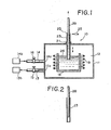
- FIG. 1 is a schematic cross-sectional view of a continuous casting furnace provided in accordance with one embodiment of the present invention;
- FIG. 2 is a cross-sectional view of a casting nozzle incorporated in the casting furnace, showing a starting wire inserted therein; and
- FIG. 3 is a cross-sectional view of a modified continuous casting furnace.
- A
continuous casting furnace 10 schematically shown in FIG. 1 comprises a box-like air-tight housing 11 of a relatively large size defining achamber 12. Anevacuation conduit 13 is connected at one end to afirst port 13a formed in the side wall of the housing 11 and at the other end to avacuum source 13b for creating a vacuum of 10-3 to 10-4 mm Hg in thechamber 12. Anotherconduit 14 is connected at one end to a second port 14a in the side wall of the housing 11 and at the other end to an inert gas source 14b for introducing inert gas into thechamber 12. Theconduits Valves conduits - A
crucible 18 for melting a casting material such as copper or its alloy is accommodated within the housing 11, thecrucible 18 having an open top through which thecrucible 18 is charged with the casting material. A high-frequency induction coil 19 is wound around thecrucible 18 so that thecrucible 18 is adapted to undergo radiofrequency induction heating to melt the casting material in thecrucible 18. - A
flanged aperture 21 is formed through a top wall of the housing 11. Acasting nozzle 23 in the form of a cross-sectionally circular tube is received in theflanged aperture 21 in an air-tight manner for sliding movement along an axis thereof, thecasting nozzle 23 being disposed vertically. Thecasting nozzle 23 may be of any polygonal cross-section such as a square cross-section. Although not shown in the drawings, thecasting nozzle 23 is provided with a water cooling means. Thecasting nozzle 23 serves as a mold for continuously casting a length of wire as hereinafter more fully described. Thecasting nozzle 23 is disposed substantially at the center of thecrucible 18 and is vertically movable by an actuator means (not shown) between an upper inoperative position in which the lower end of thecasting nozzle 23 is retracted from thecrucible 18 and a lower operative position in which the lower end of thecasting nozzle 23 is immersed in the molten casting material in thecrucible 18. Acap 25 is adapted to be removably attached to the upper end of thecasting nozzle 23 for closing it in an air-tight manner. Thecasting nozzle 23 can be made of graphite, but it is preferred that the surface of the bore of thegraphite casting nozzle 23 is coated with a protective film made, for example, of SiC when it is intended to produce the cast product of the copper alloy containing the active metals such as Zr and Cr. - The operation of the
continuous casting furnace 10 will now be described. - First, the
valve 15 is opened to evacuate thechamber 12 via theconduit 13 to a vacuum of a predetermined level. At this time, thecasting nozzle 23 is held in its upper inoperative position, and the upper end of thecasting nozzle 23 is closed by thecap 25. Then, theinduction coil 19 is energized to melt the casting material in thecrucible 18 to provide amolten casting material 26. Then, thevalve 15 is closed to stop the evacuation of thechamber 12, and subsequently thevalve 16 is opened to feed inert gas such as argon gas to thechamber 12 via theconduit 14 to increase the pressure of thechamber 12 to atmospheric pressure. Then, thecasting nozzle 23 is moved downwardly to immerse its lower end in themolten casting material 26 in thecrucible 18. Then, thecap 25 is detached from the upper end of thecasting nozzle 23. Then, one end portion of astarting wire 28 of a circular cross-section is inserted into thecasting nozzle 23 from its upper end as shown in FIG. 2, the diameter of thestarting wire 28 being slightly smaller than the inner diameter of thecasting nozzle 23. The other end of thestarting wire 28 is connected to a suitable take-up means (not shown) such as a take-up reel. Then, the pressure of the inert gas in thechamber 12 is increased to a level slightly greater than the atmospheric pressure, so that themolten casting material 26 in thecrucible 18 is moved upwardly along thecasting nozzle 23 and is brought into contact with the lower end of thestarting wire 28. Then, thestarting wire 28 is hauled upwardly either continuously or intermittently so that the molten material is cooled by the water cooling means and solidified during the passage through thecasting nozzle 23 to produce acast wire 29 having a circular cross-section corresponding to the bore of thecasting nozzle 23. Thecast wire 29 so produced is wound around the take-up reel. As the casting operation proceeds, themolten material 26 in thecrucible 18 decreases, and therefore thecasting nozzle 23 is gradually moved downwardly during the casting operation to ensure that the lower end of thecasting nozzle 23 is dipped in themolten material 26 in thecrucible 18. When themolten material 26 in thecrucible 18 is almost consumed, the casting operation is stopped. And, the above procedure is repeated. - With the
continuous casting furnace 10, the molten casting material, for example, of the copper alloy, containing active metals such as Zr, Cr and Ti, is formed in the vacuum, and this molten material is cast in the atmosphere of the inert gas. Therefore, the active metals are not subjected to oxidation, and stringers due to oxides of such active metals are not present in the resultant cast product of the copper alloy. Thus, a casting product of good quality can be obtained. In addition, by virtue of the provision of theelongate casting nozzle 23, the casting product can be obtained in the form of a wire. Therefore, an elongate final product can be easily obtained merely by drawing or rolling the cast wire into a predetermined cross-section. This will reduce the processing cost. - Further, since the
molten material 26 is urged to move along thecasting nozzle 23 under the influence of the pressure in thechamber 12 against the gravity, the molten casting material in thecasting nozzle 23 is solidified under pressure, thereby enhancing the soundness of the cast product. - Further, when the casting operation is completed, the molten material at the lower end of the
casting nozzle 23 is finally returned to thecrucible 18 upon upward movement away from thecrucible 18. Thus, themolten material 26 is subjected to substantially no loss, thereby much improving the yield. - Alternatively, in operation, the use of vacuum can be omitted. In this case, the inert gas is introduced from the inert gas source 14b into the
chamber 12 when the casting material is melted in thecrucible 18. Then, the castingnozzle 23 is moved downwardly to immerse its lower end in the molten casting material in thecrucible 18. Then, the startingwire 28 is inserted into the castingnozzle 23, and subsequently the pressure of the inert gas in thechamber 12 is increased, so that the molten casting material in thecrucible 18 is moved upwardly along the castingnozzle 23 and is brought into contact with the lower end of the startingwire 28. - FIG. 3 shows a modified continuous casting furnace 10a which comprises a housing 11 defining a
chamber 12. Anevacuation conduit 13 is connected to the housing 11, and an inert gas-feeding conduit (not shown) is also connected to the housing 11. The housing 11 is supported by legs 31 on a base 30 which is in turn supported on ahorizontal floor 32 bylegs 33. Awater jacket 34 is hermetically received in and secured to aflanged aperture 21. A castingnozzle 23 is received in thewater jacket 34, and the lower end of the castingnozzle 23 extends beyond the lower end of thewater jacket 34. Ahydraulic cylinder 35 is mounted on thebase plate 30 and extends hermetically through a bottom wall of the housing 11, thecylinder 35 having a vertically-disposed piston rod 35a operatively associated therewith. Ahorizontal support plate 36 is mounted on the upper end of the piston rod 35a. Acrucible 18 is placed on thesupport plate 36. A high-frequency induction coil 19 is wound around thecrucible 18. A mountingplate 38 is mounted on the base 30 throughlegs 39. Anelectric motor 41 is mounted on the mountingplate 38 through a mountingmember 42. An output shaft of themotor 41 is connected to a pair of opposed pinch rolls 44 through areduction gear train 45. ! - The operation of the continuous casting furnace 10a is carried out generally as described above for the
continuous casting furnace 10 of FIG. 1. More specifically, thehydraulic cylinder 35 is operated to extend its piston rod 35a to move thecrucible 18 upwardly toward the castingnozzle 35, so that the lower end of the castingnozzle 23 is immersed in amolten casting material 26 in thecrucible 18. Then, a starting wire (not shown) is inserted into the castingnozzle 23, and the pressure of the inert gas in the chamber is increased so that themolten casting material 26 in thecrucible 18 is moved upwardly along the castingnozzle 23 and is brought into contact with the lower end of the starting wire as described above for thecontinuous casting furnace 10 of FIG. 1. In this condition, the starting wire is held by the pinch rolls 44. Then, themotor 41 is operated to move the starting wire upwardly through the pinch rolls 44, so that the continuously-cast wire coming out of the castingnozzle 23 is guided by guide rolls 47, 48 and is wound around a take-up reel (not shown). The molten casting material is cooled by thewater jacket 34 when it is passed - through the casting
nozzle 23 and is solidified to form the cast wire. As the casting operation proceeds, the piston rod 35a of thehydraulic cylinder 35 is gradually extended to ensure that the lower end of the castingnozzle 23 is immersed in themolten casting material 26. - The invention will now be illustrated by way of the following EXAMPLES.
- A cross-sectionally circular wire of copper alloy containing 0.4% of Cr and 0.1% of Zr was cast using the continuous casting furnace 10a of FIG. 3. The casting
nozzle 23 was made of graphite having a protective coating of SiC formed on the surface of the bore of the nozzle, thenozzle 23 having an inner diameter of 12 mm. Thecrucible 18 was a graphite crucible (#60) and had a capacity of 50 kg. A power source for the high-frequency induction coil 19 had a capacity of 70 KW. Thechamber 12 was held at a vacuum of 1 x 10⁻⁴ mm Hg during the melting of the casting material in thecrucible 18. After this melting operation, argon gas was introduced into thechamber 12 and the pressure of the argon gas in thechamber 12 was maintained at a pressure of 1.5 kg/cm2G (the atmospheric pressure + 0.5 kg/cm2) during the casting operation. In the manner described above, the cross-sectionally circular wire of the copper alloy having a diameter of 12 mm was continuously cast. Subsequently,the cast wire was shaved to a diameter of 10 mm. Then, the diameter of the shaved wire was further reduced to 60 pm by cold rolling and drawing to form a fine wire. The structure of this wire was observed, and it was found that no stringer was present in the fine wire and that the wire had a smooth texture. During the drawing operation, the wire broke less than once per 70 Kg of the wire. Thus, the strength of the wire was excellent, and in addition the electrical conductivity of the wire was excellent. Also, the shaved wire having a diameter of 10 mm was formed by cross-rolling and rolling into a strip having a thickness of 0.2 mm and a width of 40 mm. No stringer was found in this strip. Then, the strip was subjected to plating. A plating defect occurred less than once per 1 m2 of the strip. Thus, it was well suited for use as a lead frame of an IC or-the like. - 50 Kg of a wire having a diameter of 12 mm was cast according to the same procedure of EXAMPLE 1 except that the casting material was oxygen free copper and that the casting
nozzle 23 of graphite had no coating on the surface of the bore of the nozzle. The wire was subjected to shaving, cold rolling, drawing and annealing so that the diameter of the wire was finally reduced to 25 pm to form a very fine wire. Since the casting material was melted under vacuum, the wire had a negligible amount of inclusions. Also, since the casting was carried out under pressure, casting defects did not develop in the cast wire. Further, since the cast wire coming out of the castingnozzle 23 had such a small diameter as 12 mm, a hot rolling operation could be omitted, so that the cast wire did not have any scales which would otherwise develop during such a hot rolling. Therefore, the cast wire did not break during the later stage processing described above.
Claims (7)
Priority Applications (1)
| Application Number | Priority Date | Filing Date | Title |
|---|---|---|---|
| AT84113523T ATE33776T1 (en) | 1983-11-11 | 1984-11-09 | FURNACE FOR CONTINUOUS CASTING AND METHOD FOR CONTINUOUS CASTING OF A PRODUCT. |
Applications Claiming Priority (2)
| Application Number | Priority Date | Filing Date | Title |
|---|---|---|---|
| JP211839/83 | 1983-11-11 | ||
| JP58211839A JPS60106648A (en) | 1983-11-11 | 1983-11-11 | Casting furnace |
Publications (2)
| Publication Number | Publication Date |
|---|---|
| EP0142139A1 true EP0142139A1 (en) | 1985-05-22 |
| EP0142139B1 EP0142139B1 (en) | 1988-04-27 |
Family
ID=16612436
Family Applications (1)
| Application Number | Title | Priority Date | Filing Date |
|---|---|---|---|
| EP84113523A Expired EP0142139B1 (en) | 1983-11-11 | 1984-11-09 | Continuous casting furnace and method of continuously manufacturing cast product |
Country Status (9)
| Country | Link |
|---|---|
| US (1) | US4688625A (en) |
| EP (1) | EP0142139B1 (en) |
| JP (1) | JPS60106648A (en) |
| KR (1) | KR890003406B1 (en) |
| AT (1) | ATE33776T1 (en) |
| CA (1) | CA1221221A (en) |
| DE (1) | DE3470674D1 (en) |
| FI (1) | FI844420A7 (en) |
| HK (1) | HK3289A (en) |
Cited By (5)
| Publication number | Priority date | Publication date | Assignee | Title |
|---|---|---|---|---|
| EP0801137A1 (en) * | 1996-04-08 | 1997-10-15 | Matsushita Electric Industrial Co., Ltd. | Process for recovering copper from insulated copper wire windings |
| WO1998023398A1 (en) * | 1996-11-29 | 1998-06-04 | Bicc Public Limited Company | Manufacture of copper wire |
| CN102927816A (en) * | 2012-11-18 | 2013-02-13 | 昆山市大金机械设备厂 | Induction heating furnace |
| WO2014001848A1 (en) * | 2012-06-29 | 2014-01-03 | Le Bronze Industriel | Crucible for a machine for continuously casting a bar or a coil of a metal alloy |
| CN112247116A (en) * | 2020-10-23 | 2021-01-22 | 东风汽车有限公司 | Low-pressure casting process of motor casing with cooling water channel |
Families Citing this family (10)
| Publication number | Priority date | Publication date | Assignee | Title |
|---|---|---|---|---|
| JPS6490991A (en) * | 1987-10-02 | 1989-04-10 | Mitsubishi Metal Corp | Product extractor for vacuum hot-water supply facility |
| JP2681944B2 (en) * | 1987-10-13 | 1997-11-26 | 三菱マテリアル株式会社 | Vacuum melting-composite mold for pressure continuous casting |
| JPH0510235Y2 (en) * | 1987-10-23 | 1993-03-12 | ||
| JP3003914B2 (en) | 1994-10-25 | 2000-01-31 | 日鉱金属株式会社 | Method for producing copper alloy containing active metal |
| IT1307538B1 (en) * | 1999-12-27 | 2001-11-06 | Silvana Lastrucci | HOT DRAWING MACHINE |
| KR101311580B1 (en) * | 2009-03-27 | 2013-09-26 | 티타늄 메탈스 코포레이션 | Method and apparatus for semi-continuous casting of hollow ingots |
| JP2015096269A (en) * | 2013-11-15 | 2015-05-21 | トヨタ自動車株式会社 | Pull-up type continuous casting apparatus and pull-up type continuous casting method |
| JP6123644B2 (en) * | 2013-11-15 | 2017-05-10 | トヨタ自動車株式会社 | Pull-up type continuous casting apparatus and pull-up type continuous casting method |
| CN106180616A (en) * | 2016-08-10 | 2016-12-07 | 安徽晋源铜业有限公司 | A kind of high-purity oxygen-free high conductivity type copper bar and processing method thereof |
| CN113857443B (en) * | 2021-09-28 | 2024-01-12 | 杭州奥宇金属制品有限公司 | Copper or copper alloy ultra-microfilament upward-guiding equipment and upward-guiding production process |
Citations (2)
| Publication number | Priority date | Publication date | Assignee | Title |
|---|---|---|---|---|
| DE903137C (en) * | 1948-12-12 | 1954-02-01 | Fritz Baessler | Method and device for casting metals |
| FR1344168A (en) * | 1961-08-05 | 1963-11-29 | Michelin & Cie | Continuous casting process of metal products of indeterminate length under small section and installation for its implementation |
Family Cites Families (8)
| Publication number | Priority date | Publication date | Assignee | Title |
|---|---|---|---|---|
| DE1218120B (en) * | 1958-12-18 | 1966-06-02 | Karl Heinz Steigerwald Dipl Ph | Device for continuous casting of metal bars |
| US3287773A (en) * | 1963-12-03 | 1966-11-29 | Amsted Ind Inc | Method of level control for continuous casting |
| US3900064A (en) * | 1972-12-04 | 1975-08-19 | Hitchiner Manufacturing Co | Metal casting |
| FR2296483A1 (en) * | 1975-01-02 | 1976-07-30 | Lajoye Pierre | PROCESS FOR THE VACUUM MELTING AND CENTRIFUGAL CASTING OF METALS, DEVICE FOR ITS IMPLEMENTATION AND PARTS OBTAINED |
| JPS538329A (en) * | 1976-07-12 | 1978-01-25 | Hitachi Metals Ltd | Method of making thin alloy sheet |
| JPS55136555A (en) * | 1979-04-11 | 1980-10-24 | Hitachi Ltd | Low-pressure casting method |
| JPS55147464A (en) * | 1979-05-08 | 1980-11-17 | Arbed | Method and device for manufacturing hollow material |
| JPS575651A (en) * | 1980-06-12 | 1982-01-12 | Teijin Seiki Co Ltd | Preparation of material to be fried |
-
1983
- 1983-11-11 JP JP58211839A patent/JPS60106648A/en active Granted
-
1984
- 1984-11-02 CA CA000466991A patent/CA1221221A/en not_active Expired
- 1984-11-09 AT AT84113523T patent/ATE33776T1/en active
- 1984-11-09 FI FI844420A patent/FI844420A7/en not_active Application Discontinuation
- 1984-11-09 DE DE8484113523T patent/DE3470674D1/en not_active Expired
- 1984-11-09 EP EP84113523A patent/EP0142139B1/en not_active Expired
- 1984-11-10 KR KR1019840007049A patent/KR890003406B1/en not_active Expired
-
1986
- 1986-05-30 US US06/871,123 patent/US4688625A/en not_active Expired - Lifetime
-
1989
- 1989-01-12 HK HK32/89A patent/HK3289A/en not_active IP Right Cessation
Patent Citations (2)
| Publication number | Priority date | Publication date | Assignee | Title |
|---|---|---|---|---|
| DE903137C (en) * | 1948-12-12 | 1954-02-01 | Fritz Baessler | Method and device for casting metals |
| FR1344168A (en) * | 1961-08-05 | 1963-11-29 | Michelin & Cie | Continuous casting process of metal products of indeterminate length under small section and installation for its implementation |
Cited By (6)
| Publication number | Priority date | Publication date | Assignee | Title |
|---|---|---|---|---|
| EP0801137A1 (en) * | 1996-04-08 | 1997-10-15 | Matsushita Electric Industrial Co., Ltd. | Process for recovering copper from insulated copper wire windings |
| US6235074B1 (en) | 1996-04-08 | 2001-05-22 | Matsushita Electric Industrial Co., Ltd. | Process of recovering copper from winding |
| WO1998023398A1 (en) * | 1996-11-29 | 1998-06-04 | Bicc Public Limited Company | Manufacture of copper wire |
| WO2014001848A1 (en) * | 2012-06-29 | 2014-01-03 | Le Bronze Industriel | Crucible for a machine for continuously casting a bar or a coil of a metal alloy |
| CN102927816A (en) * | 2012-11-18 | 2013-02-13 | 昆山市大金机械设备厂 | Induction heating furnace |
| CN112247116A (en) * | 2020-10-23 | 2021-01-22 | 东风汽车有限公司 | Low-pressure casting process of motor casing with cooling water channel |
Also Published As
| Publication number | Publication date |
|---|---|
| HK3289A (en) | 1989-01-20 |
| JPS6338263B2 (en) | 1988-07-29 |
| FI844420A0 (en) | 1984-11-09 |
| FI844420L (en) | 1985-05-12 |
| KR850004028A (en) | 1985-07-01 |
| FI844420A7 (en) | 1986-05-10 |
| DE3470674D1 (en) | 1988-06-01 |
| JPS60106648A (en) | 1985-06-12 |
| ATE33776T1 (en) | 1988-05-15 |
| EP0142139B1 (en) | 1988-04-27 |
| KR890003406B1 (en) | 1989-09-20 |
| CA1221221A (en) | 1987-05-05 |
| US4688625A (en) | 1987-08-25 |
Similar Documents
| Publication | Publication Date | Title |
|---|---|---|
| EP0142139B1 (en) | Continuous casting furnace and method of continuously manufacturing cast product | |
| EP1598433B1 (en) | Method for continuously producing low-oxygen copper wire | |
| US3658119A (en) | Apparatus for processing molten metal in a vacuum | |
| EP0471798B1 (en) | Induction skull melt spinning of reactive metal alloys | |
| KR860000126B1 (en) | Method of electromagnetic thin strip casting | |
| JPS6116215B2 (en) | ||
| US6287364B1 (en) | Method for producing copper alloy ingot | |
| Kunstreich | Electromagnetic stirring for continuous casting-Part 2 | |
| US3635279A (en) | Method of casting an ingot in a thin-walled deformable steel mould | |
| JP3250241B2 (en) | Target material and its manufacturing method | |
| CN115418724B (en) | Directional solidification device, directional solidification method and forming method for platinum iridium alloy rod | |
| JPS6352983B2 (en) | ||
| US3544757A (en) | Method of melting a levitated mass | |
| JPH0531568A (en) | Plasma melting casting method | |
| EP0124684B1 (en) | Casting in a thermally-induced, low density atmosphere | |
| JP2002361376A (en) | Vertical casting method and apparatus | |
| JPH11285788A (en) | Continuous casting method of large section slab for thick steel plate | |
| JPS61132248A (en) | Method and device for continuous production of clad material | |
| JP3310884B2 (en) | Electromagnetic casting of steel | |
| CN110405167A (en) | Metal level solidification research device and method under a kind of time-varying magnetic field | |
| CN85101474A (en) | The method of continuous casting furnace and continuous production foundry goods | |
| KR20260052485A (en) | Continuous casting method using vertical bottom-feeding for copper alloy wire production | |
| JPH02251338A (en) | Method for casting metal for plastic working | |
| JP2003048052A (en) | Manufacturing method and manufacturing apparatus for wire drawing ingot | |
| JPH05104208A (en) | Plasma melting and casting method |
Legal Events
| Date | Code | Title | Description |
|---|---|---|---|
| PUAI | Public reference made under article 153(3) epc to a published international application that has entered the european phase |
Free format text: ORIGINAL CODE: 0009012 |
|
| AK | Designated contracting states |
Designated state(s): AT BE DE FR GB |
|
| 17P | Request for examination filed |
Effective date: 19850813 |
|
| 17Q | First examination report despatched |
Effective date: 19860919 |
|
| GRAA | (expected) grant |
Free format text: ORIGINAL CODE: 0009210 |
|
| AK | Designated contracting states |
Kind code of ref document: B1 Designated state(s): AT BE DE FR GB |
|
| REF | Corresponds to: |
Ref document number: 33776 Country of ref document: AT Date of ref document: 19880515 Kind code of ref document: T |
|
| REF | Corresponds to: |
Ref document number: 3470674 Country of ref document: DE Date of ref document: 19880601 |
|
| ET | Fr: translation filed | ||
| PLBE | No opposition filed within time limit |
Free format text: ORIGINAL CODE: 0009261 |
|
| STAA | Information on the status of an ep patent application or granted ep patent |
Free format text: STATUS: NO OPPOSITION FILED WITHIN TIME LIMIT |
|
| 26N | No opposition filed | ||
| REG | Reference to a national code |
Ref country code: FR Ref legal event code: CD Ref country code: FR Ref legal event code: CA |
|
| PGFP | Annual fee paid to national office [announced via postgrant information from national office to epo] |
Ref country code: AT Payment date: 19961126 Year of fee payment: 13 |
|
| PG25 | Lapsed in a contracting state [announced via postgrant information from national office to epo] |
Ref country code: AT Free format text: LAPSE BECAUSE OF NON-PAYMENT OF DUE FEES Effective date: 19971109 |
|
| PGFP | Annual fee paid to national office [announced via postgrant information from national office to epo] |
Ref country code: GB Payment date: 20001013 Year of fee payment: 17 |
|
| PGFP | Annual fee paid to national office [announced via postgrant information from national office to epo] |
Ref country code: FR Payment date: 20001101 Year of fee payment: 17 |
|
| PGFP | Annual fee paid to national office [announced via postgrant information from national office to epo] |
Ref country code: DE Payment date: 20001102 Year of fee payment: 17 |
|
| PGFP | Annual fee paid to national office [announced via postgrant information from national office to epo] |
Ref country code: BE Payment date: 20001116 Year of fee payment: 17 |
|
| PG25 | Lapsed in a contracting state [announced via postgrant information from national office to epo] |
Ref country code: GB Free format text: LAPSE BECAUSE OF NON-PAYMENT OF DUE FEES Effective date: 20011109 |
|
| PG25 | Lapsed in a contracting state [announced via postgrant information from national office to epo] |
Ref country code: BE Free format text: LAPSE BECAUSE OF NON-PAYMENT OF DUE FEES Effective date: 20011130 |
|
| REG | Reference to a national code |
Ref country code: GB Ref legal event code: IF02 |
|
| BERE | Be: lapsed |
Owner name: MITSUBISHI MATERIAL CORP. Effective date: 20011130 |
|
| GBPC | Gb: european patent ceased through non-payment of renewal fee |
Effective date: 20011109 |
|
| PG25 | Lapsed in a contracting state [announced via postgrant information from national office to epo] |
Ref country code: DE Free format text: LAPSE BECAUSE OF NON-PAYMENT OF DUE FEES Effective date: 20020702 |
|
| PG25 | Lapsed in a contracting state [announced via postgrant information from national office to epo] |
Ref country code: FR Free format text: LAPSE BECAUSE OF NON-PAYMENT OF DUE FEES Effective date: 20020730 |
|
| REG | Reference to a national code |
Ref country code: FR Ref legal event code: ST |
|
| REG | Reference to a national code |
Ref country code: FR Ref legal event code: ST |