EP0142007A1 - Packaging machine - Google Patents
Packaging machine Download PDFInfo
- Publication number
- EP0142007A1 EP0142007A1 EP84111931A EP84111931A EP0142007A1 EP 0142007 A1 EP0142007 A1 EP 0142007A1 EP 84111931 A EP84111931 A EP 84111931A EP 84111931 A EP84111931 A EP 84111931A EP 0142007 A1 EP0142007 A1 EP 0142007A1
- Authority
- EP
- European Patent Office
- Prior art keywords
- mobile drive
- packaging
- control device
- packaging machine
- adjusting screws
- Prior art date
- Legal status (The legal status is an assumption and is not a legal conclusion. Google has not performed a legal analysis and makes no representation as to the accuracy of the status listed.)
- Granted
Links
- 238000004806 packaging method and process Methods 0.000 title claims abstract description 22
- 230000001419 dependent effect Effects 0.000 claims abstract description 4
- 239000005022 packaging material Substances 0.000 claims abstract 2
- 230000008878 coupling Effects 0.000 claims description 7
- 238000010168 coupling process Methods 0.000 claims description 7
- 238000005859 coupling reaction Methods 0.000 claims description 7
- 238000000034 method Methods 0.000 claims description 3
- 238000007493 shaping process Methods 0.000 claims description 3
- 238000012856 packing Methods 0.000 claims description 2
- 230000008859 change Effects 0.000 description 5
- 230000008901 benefit Effects 0.000 description 2
- 238000006073 displacement reaction Methods 0.000 description 2
- 230000006870 function Effects 0.000 description 2
- 238000003780 insertion Methods 0.000 description 2
- 230000037431 insertion Effects 0.000 description 2
- 241001136792 Alle Species 0.000 description 1
- 206010012335 Dependence Diseases 0.000 description 1
- 239000000969 carrier Substances 0.000 description 1
- 238000006243 chemical reaction Methods 0.000 description 1
- 238000010276 construction Methods 0.000 description 1
- 238000011161 development Methods 0.000 description 1
- 230000018109 developmental process Effects 0.000 description 1
- 238000010586 diagram Methods 0.000 description 1
- 238000012545 processing Methods 0.000 description 1
Images

Classifications
-
- B—PERFORMING OPERATIONS; TRANSPORTING
- B65—CONVEYING; PACKING; STORING; HANDLING THIN OR FILAMENTARY MATERIAL
- B65B—MACHINES, APPARATUS OR DEVICES FOR, OR METHODS OF, PACKAGING ARTICLES OR MATERIALS; UNPACKING
- B65B59/00—Arrangements to enable machines to handle articles of different sizes, to produce packages of different sizes, to vary the contents of packages, to handle different types of packaging material, or to give access for cleaning or maintenance purposes
- B65B59/001—Arrangements to enable adjustments related to the product to be packaged
-
- B—PERFORMING OPERATIONS; TRANSPORTING
- B65—CONVEYING; PACKING; STORING; HANDLING THIN OR FILAMENTARY MATERIAL
- B65B—MACHINES, APPARATUS OR DEVICES FOR, OR METHODS OF, PACKAGING ARTICLES OR MATERIALS; UNPACKING
- B65B59/00—Arrangements to enable machines to handle articles of different sizes, to produce packages of different sizes, to vary the contents of packages, to handle different types of packaging material, or to give access for cleaning or maintenance purposes
- B65B59/003—Arrangements to enable adjustments related to the packaging material
Definitions
- the invention relates to a packaging machine according to the preamble of the main claim.
- the individual processing and handling devices such as Feeding, conveying, folding, shaping and closing devices set up adjustable.
- the adjustable parts have slots through which releasable clamping screws engage, or they are fastened to slide guides which can be displaced with adjusting screws in a finely adjustable manner.
- the conversion of the known machines to another format takes a lot of time. In the case of complicated machines, for example cartoning machines, up to a hundred or more parts and tools have to be reset.
- Cartoning machines in which individual tools and components are equipped with a motor-driven adjusting device have also become known.
- the adjustment devices provided with a position transmitter can be controlled by a central control device in which format-dependent data are stored.
- Such adjustment devices are advantageous on components that are difficult to see and access. Equipping all the tools and components of a packaging machine that can be converted depending on the format requires a very high level of construction. Furthermore, there is no space available for drive motors in many places on the machine.
- the packaging machine according to the invention with the characterizing features of the main claim has the advantage that a format change can be carried out selectively and very quickly, and readjustments can be omitted.
- a format change can be carried out by an operator who does not have extensive machine knowledge and experience, but can be trained.
- control unit can control the predetermined target positions of the components quickly and precisely.
- FIG. 1 shows a cartoning machine simplified in a diagrammatic representation
- FIG. 2 shows a folding device of the packaging machine according to FIG. 1 with an adjusting device in a diagrammatic representation
- FIG. 3 shows a mobile drive simplified for actuators
- Figure 4 is a block diagram of a controller for the mobile drive.
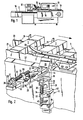
- a cartoning machine 10 which is shown by way of example for a packaging machine, has a product feed device 11, a brochure folder 12, a folding box magazine 13, a folding box conveyor device 14 with driver fingers 15, a product insertion device 16, a folding and closing device 17 a spout 18 and a control device 19.
- the devices 11 to 18 of the cartoning machine 10 have adjustable tools and components in a certain range, so that the machine for packing objects with different dimensions in folding boxes 1 with an adapted length, width and height can be changed.
- FIG. 2 For the convertibility of the devices 11 to 18, only one folding rail 20 of the folding and closing device 17 for folding over an insertion flap 2 on an end flap 3 of the folding boxes 1 is shown and explained by way of example (FIG. 2).
- the folding rail 20 is to be positioned in a specific position with respect to support rails 21, 22 of the conveying device 14, a folding switch 23 and a folding slide 24 which is moved in cycles.
- the folding rail 20 is carried by an angled arm 26 which is fastened to a slide 27 of a sliding guide 25 with screws 28.
- the carriage 27 is slidable on a guide rail 30 extends in a horizontal plane transverse to the conveying direction of the folding box conveyor 14 and the longitudinal extent of the folding rail 20.
- a set screw 32 is rotatably but not axially displaceably mounted in a bearing block 31 on the guide rail 30 and engages with its threaded part in a threaded bore 34 of an eye 33 on the carriage 27.
- the set screw 32 has a head 35 with a hexagon recess 36 with which a hexagon pin of a tool can be coupled in a form-fitting manner.
- the carriage 27 with the arm 26 and the folding rail 20 is moved horizontally.
- the one end position of the slide 27, in which the slide 27 rests on the rail 30 at the foot of the bearing block 31, is referred to as the reference zero position, which will be discussed in more detail below.
- the guide rail 30 is not rigidly attached to the machine frame 37, but can be moved vertically with a right-angled arm 38 in a carriage 40 fixedly attached to the machine frame 37 with screws 39.
- the second sliding guide 41 consisting of the arm 38 and the slide 40 has, like the sliding guide 25, an adjusting screw 32 with a head 35 and an eye 33 with a threaded bore 34 and a bearing block 31.
- the head 35 of the adjusting screw 32 arranged below the guide rail 30 second slide guide 41 is accessible from above for coupling a tool
- the guide rail 30 has an elongated hole 43 in extension to the set screw 32.
- the arm 26 has an opening 44 through which the guide rail 30 engages.
- 40 screwed a releasable locking screw 45, which presses on the guide rail 30 and 38, respectively.
- the other devices 11 to 18 and their components are equipped, which can be adjusted to different formats of the products to be packaged and the folding boxes used, with a single slide guide for one-dimensional adjustment and two for two-dimensional adjustment angularly coupled sliding guides are arranged.
- the coupling piece 51 can also be arranged on an extension which can be connected to the drive unit 50.
- the drive unit 50 contains an electric motor 49 which can be switched in the direction of rotation and a position transmitter 52.
- the position transmitter 52 which generates electrical signals as a function of the respective position of a sliding guide, is preferably of the type which generates a specific number of electrical pulses per revolution.
- the drive unit 50 has a push-button contact 53 which can be actuated by finger.
- the drive unit 50 is connected to a switching device 55 by means of a multi-core cable 54.
- This switching device 55 is in turn by means of a cable 56 and a plug 57 with one of several connections 58 a distributor or ring line 59 connectable, which leads to the central control device 19.
- the switching device 55 has a light indicator 61 for the identification number of the changeover point to be addressed, a light indicator 62 for the position, an input keyboard 63 with preselection keys for entering, deleting and correcting numbers of the changeover points and positions, as well as a plurality of indicator lights 64 an amplifier 65 is provided.
- the switching device 55 which can also be attached to the mobile drive unit 50, is not stationary, like the mobile drive unit, so that the operator takes it along with the mobile drive unit 50 to the respective changeover point of the machine and initiate and monitor a changeover there can.
- control device 19 also has an input keyboard 71 with the same functions as that of the input keyboard 61.
- control device 19 has two operating mode switches 68, 69.
- a monitor 72 is arranged on the control device 19, on which the operator can see Information and instructions can be displayed under program control.
- control device 19 contains a memory 73 for storing the data of the individual changeover points of the machine, provided with identification numbers, for several formats, as well as programs for the sequence of the changeovers. The stored and entered data and signals are processed by a microprocessor 74 and forwarded as signals.
- the keyboard 7J, the monitor 72, the memory 73, the microprocessor 74, the switching device 55 and the mobile drive unit 50 are connected to one another via two interfaces 75, 76 the. Signals about the respective positions of movable components and tools of the machine can also be input into the control system via the interface 75.
- the individual programs and data are stored in the memory 73. If the data exceeds the capacity of the memory 73, other programs can also be introduced into the control device 19 on floppy disks and similar data carriers.
- the data for the individual programs can be entered into the memory via the keyboard 71 of the control unit on the basis of the known displacement paths. However, they can also be recorded and entered empirically by the changeover points are first adjusted by hand to the format and then the sliding guide 25 of each changeover point is moved back to the reference zero position with the mobile drive unit 50.
- the signals generated by the position transmitter 52 of the drive unit 50 are forwarded to the microprocessor 74, evaluated by the latter and stored in the memory 73.
- stationary drive units are arranged at changeover points that are not accessible, which in addition to a drive motor also have a position transmitter. These changeover points are set during the course of the selected program or by input from the operator via the keyboard 71 of the control unit 19.
Landscapes
- Engineering & Computer Science (AREA)
- Mechanical Engineering (AREA)
- Auxiliary Devices For And Details Of Packaging Control (AREA)
- Container Filling Or Packaging Operations (AREA)
- Closing Of Containers (AREA)
Abstract
Zum Einstellen von verschiedenen Formaten in Abhängigkeit der zu verpackenden Produkte und Packmittel sind Bauteile, Werkzeuge und Einrichtungen einer Verpackungsmaschine einstellbar eingerichtet. Um mit Stellschrauben (32) ausgerüstete, verchiebbare Teile der einzelnen Umstellstellen gezielt und schnell Einstellen zu können, hat die Verpackungsmaschine eine mobile Antriebseinheit (50), die mit den Stellschrauben der einzelnen Umstellstellen kuppelbar ist. Die Antriebseinheit wird von einem formatabhängig programmierbaren Steuergerät (19) gesteuert und von einer Bedienungsperson an jeweils der vom Steuergerät angezeigten Umstellstelle angesetzt.Components, tools and equipment of a packaging machine are set up in an adjustable manner for setting different formats depending on the products and packaging materials to be packaged. The packaging machine has a mobile drive unit (50), which can be adjusted and displaceable parts of the individual changeover points equipped with adjusting screws (32) in a targeted manner and can be coupled with the adjusting screws of the individual changeover points. The drive unit is controlled by a format-dependent programmable control device (19) and is set by an operator at the changeover point indicated by the control device.
Description
Die Erfindung geht aus von einer Verpackungsmaschine nach der Gattung des Hauptanspruchs. Zum Anpassen der Maschine an die Form und Größe der jeweils zu verpakkenden Produkte und der dazu verwendeten Packmittel, wie Schachteln, Beutel, Einwickler, Dosen, Flaschen, Schalen und dergleichen - in Fachkreisen Formatumstellung genannt -, sind die einzelnen Bearbeitungs- und Handhabungsvorrichtungen, wie Zuführ-, Förder-, Falt-, Form- und Schließvorrichtungen einstellbar eingerichtet. Dazu haben, wie beispielsweise die US-PS 3 509 681 zeigt, die verstellbaren Teile Schlitze, durch die lösbare Klemmschrauben greifen, oder sie sind an Gleitführungen befestigt, die mit Stellschrauben fein einstellbar verschiebbar sind. Die Umstellung der bekannten Maschinen auf ein anderes Format erfordert jeweils viel Zeit. Bei komplizierten Maschinen, beispielsweise Kartoniermaschinen, sind dazu bis zu hundert und auch mehr Teile und Werkzeuge jeweils neu einzustellen.The invention relates to a packaging machine according to the preamble of the main claim. To adapt the machine to the shape and size of the products to be packaged and the packaging used, such as boxes, bags, wrappers, cans, bottles, trays and the like - called format change in specialist circles - are the individual processing and handling devices, such as Feeding, conveying, folding, shaping and closing devices set up adjustable. For this purpose, as shown, for example, in US Pat. No. 3,509,681, the adjustable parts have slots through which releasable clamping screws engage, or they are fastened to slide guides which can be displaced with adjusting screws in a finely adjustable manner. The conversion of the known machines to another format takes a lot of time. In the case of complicated machines, for example cartoning machines, up to a hundred or more parts and tools have to be reset.
Ferner setzt eine Formatumstellung umfangreiche Kenntnisse und Erfahrungen der Bedienungsperson voraus, da die einzelnen Bauteile und Werkzeuge anhand von Produkt- und Packmittelmuttern eingestellt werden müssen. An vielen Stellen ist die Einstellung auch von der Stellung eines voreingestellten Teiles abhängig, so daß nach einer Falscheinstellung eines ersten Teils oder Werkzeugs, dieses und davon abhängige Teile wieder nachgestellt werden müssen. Schließlich kommt hinzu, daß nach abgeschlossener Umstellung der Maschine wegen der Toleranzen und Schwankungen der Produkte und Packmittel wiederholt Nachjustierungen vorgenommen werden müssen, um einen störungsfreien Betrieb sicherzustellen. Solche nachträglichen Justierungen erfordern oft ein Vielfaches der vorgängigen Umstellzeit.Furthermore, a format changeover requires extensive knowledge and experience of the operator, since the individual components and tools must be set using product and packaging nuts. In many places, the setting also depends on the position of a preset part, so that after a wrong setting of a first part or tool, this and dependent parts must be readjusted. Finally, after the changeover of the machine has been completed, readjustments have to be carried out repeatedly to ensure trouble-free operation due to the tolerances and fluctuations in the products and packaging. Such subsequent adjustments often require a multiple of the previous changeover time.
Es sind auch schon Kartoniermaschinen bekanntgeworden, bei denen einzelne Werkzeuge und Bauteile mit einer motorgetriebenen Verstelleinrichtung ausgerüstet sind. Die mit einem Positionsgeber versehenen Verstelleinrichtungen können von einem zentralen Steuergerät angesteuert werden, in dem formatabhängige Daten gespeichert sind. Solche Verstelleinrichtungen sind an Bauteilen von Vorteil, die schlecht einsehbar und zugänglich sind. Alle formatabhängig umstellbaren Werkzeuge und Bauteile einer Verpackungsmaschine derart auszurüsten, erfordert einen sehr hohen Bauaufwand. Ferner steht an vielen Stellen der Maschine für Antriebsmotoren kein Platz zur Verfügung.Cartoning machines in which individual tools and components are equipped with a motor-driven adjusting device have also become known. The adjustment devices provided with a position transmitter can be controlled by a central control device in which format-dependent data are stored. Such adjustment devices are advantageous on components that are difficult to see and access. Equipping all the tools and components of a packaging machine that can be converted depending on the format requires a very high level of construction. Furthermore, there is no space available for drive motors in many places on the machine.
Es ist daher Aufgabe der Erfindung, eine Verpackungsmaschine so einzurichten, daß eine Formatumstellung in kurzer Zeit und möglichst unter Vermeidung von Nachjustierungen durchführbar ist.It is therefore an object of the invention to set up a packaging machine in such a way that a format change can be carried out in a short time and as far as possible while avoiding readjustments.
Die erfindungsgemäße Verpackungsmaschine mit den kennzeichnenden Merkmalen des Hauptanspruchs hat den Vorteil, daß eine Formatumstellung gezielt und sehr schnell durchgeführt werden kann, und Nachjustierungen unterbleiben können. Außerdem kann eine Formatumstellung von einer Bedienungsperson vorgenommen werden, welche keine umfangreichen Maschinenkenntnisse und Erfahrungen hat, sondern angelernt sein kann.The packaging machine according to the invention with the characterizing features of the main claim has the advantage that a format change can be carried out selectively and very quickly, and readjustments can be omitted. In addition, a format change can be carried out by an operator who does not have extensive machine knowledge and experience, but can be trained.
Durch die in den Unteransprüchen aufgeführten Maßnahmen sind vorteilhafte Weiterbildungen und Verbesserungen der im Hauptanspruch angegebenen Verpackungsmaschine möglich. Insbesondere ist dabei die Anzeige der jeweils zu betätigenden Umstellstelle vorteilhaft, so daß die einzelnen Umstellstellen in der richtigen Reihenfolge von der Bedienungsperson angegangen werden können.Advantageous further developments and improvements of the packaging machine specified in the main claim are possible through the measures listed in the subclaims. In particular, the display of the changeover point to be actuated is advantageous so that the individual changeover points can be addressed by the operator in the correct order.
Bei einem Verfahren zum Formatumstellen einer Verpakkungsmaschine nach dem Hauptanspruch lassen sich durch die Steuerung des Steuergeräts die vorgegebenen Sollstellungen der Bauteile schnell und präzise einstellen.In a method for changing the format of a packaging machine according to the main claim, the control unit can control the predetermined target positions of the components quickly and precisely.
Ein Ausführungsbeispiel der Erfindung ist in der Zeichnung dargestellt und in der nachfolgenden Beschreibung näher erläutert. Es zeigen Figur 1 eine Kartoniermaschine vereinfacht in schaubildlicher Darstellung, Figur 2 eine Falteinrichtung der Verpackungsmaschine nach Figur 1 mit einer Verstelleinrichtung in schaubildlicher Darstellung, Figur 3 einen mobilen Antrieb für Stelleinrichtungen.vereinfacht und Figur 4 ein Blockschaltbild einer Steuerung für den mobilen Antrieb.An embodiment of the invention is shown in the drawing and explained in more detail in the following description. 1 shows a cartoning machine simplified in a diagrammatic representation, FIG. 2 shows a folding device of the packaging machine according to FIG. 1 with an adjusting device in a diagrammatic representation, FIG. 3 shows a mobile drive simplified for actuators and Figure 4 is a block diagram of a controller for the mobile drive.
Eine Kartoniermaschine 10, die beispielhaft für eine Verpackungsmaschine dargestellt ist, hat eine Produktzuführeinrichtung 11, einen Prospekt-Falzapparat 12, ein Faltschachtel-Magazin 13, eine Faltschachtel-Fördereinrichtung 14 mit Mitnehmerfingern 15, eine Produkt-Einschubeinrichtung 16, eine Falt- und Schließeinrichtung 17 einen Auslauf 18 und ein Steuergerät 19. Die Einrichtungen 11 bis 18 der Kartoniermaschine 10 haben in einem bestimmten Bereich einstellbare Werkzeuge und Bauteile, so daß die Maschine zum Verpacken von Gegenständen mit verschiedenen Abmessungen in Faltschachteln 1 mit angepaßter Länge, Breite und Höhe ein- oder umgestellt werden kann.A
Für die Umstellbarkeit der Einrichtungen 11 bis 18 ist im folgenden beispielhaft lediglich eine Faltschiene 20 der Falt- und Schließeinrichtung 17 zum Umlegen eines Einstecklappens 2 an einer Stirnlasche 3 der Faltschachteln 1 darstellt (Figur 2) und erläutert. Je nach der Länge und Höhe der verarbeiteten Faltschachteln 1 ist die Faltschiene 20 in einer bestimmten Stellung in bezug zu Tragschienen 21, 22 der Fördereinrichtung 14, einer Faltweiche 23 und einem taktweise bewegten Faltschieber 24 zu positionieren.For the convertibility of the
Die Faltschiene 20 wird von einem abgewinkelten Arm 26 getragen, der an einem Schlitten 27 einer Gleitführung 25 mit Schrauben 28 befestigt ist. Der Schlitten 27 ist auf einer Führungsschiene 30 verschiebbar, die sich in waagrechter Ebene quer zur Förderrichtung der Faltschachtel-Fördereinrichtung 14 und der Längserstreckung der Faltschiene 20 erstreckt. Zum Verschieben des Schlittens 27 auf der Führungsschiene 30 ist in einem Lagerbock 31 auf der Führungsschiene 30 eine Stellschraube 32 drehbar aber nicht axial verschiebbar gelagert, die mit ihrem Gewindeteil in eine Gewindebohrung 34 eines Auges 33 am Schlitten 27 greift. Die Stellschraube 32 hat einen Kopf 35 mit einer Sechskantaussparung 36, mit der ein Sechskantzapfen eines Werkzeugs formschlüssig kuppelbar ist. Durch Drehen der Stellschraube 32 in der einen oder anderen Richtung wird der Schlitten 27 mit dem Arm 26 und der Faltschiene 20 waagrecht verschoben. Die eine Endstellung des Schlittens 27, in der der Schlitten 27 am Fuß des Lagerbocks 31 auf der Schiene 30 anliegt, wird als Bezugs-Nullstellung bezeichnet, auf die weiter unten noch näher eingegangen wird.The folding
Da die Faltschiene 20 auch in ihrer Höhenlage einstellbar sein muß, ist die Führungsschiene 30 nicht starr am Maschinengestell 37 befestigt, sondern mit einem rechtwinklig abgewinkelten Arm 38 in einem ortsfest am Maschinengestell 37 mit Schrauben 39 befestigten Schlitten 40 senkrecht verschiebbar. Die aus dem Arm 38 und dem Schlitten 40 bestehende zweite Gleitführung 41 hat gleichermaßen wie die Gleitführung 25 eine Stellschraube 32 mit Kopf 35 und ein Auge 33 mit Gewindebohrung 34 sowie einen Lagerbock 31. Damit der unterhalb der Führungsschiene 30 angeordnete Kopf 35 der Stellschraube 32 der zweiten Gleitführung 41 von oben her zum Ankuppeln eines Werkzeugs zugänglich ist, hat die Führungsschiene 30 in Verlängerung zu der Stellschraube 32 ein Langloch 43. Ferner hat der Arm 26 einen Durchbruch 44, durch den die Führungsschiene 30 greift. Um die Gleitführungen 25, 41 in bestimmten Stellungen festzustellen, ist in den Schlitten 27, 40 eine lösbare Feststellschraube 45 eingeschraubt, welche auf die Führungsschiene 30 bzw. 38 drückt.Since the folding
Mit den gleichen, oben beschriebenen Gleitführungen 25, 41 sind auch die anderen Einrichtungen 11 bis 18 und deren Bauteile ausgerüstet, die auf verschiedene Formate der zu verpackenden Produkte und der verwendeten Faltschachteln einstellbar sind, wobei bei eindimensionaler Verstellung eine einzige Gleitführung und bei zweidimensionaler Einstellung zwei winkelig gekuppelte Gleitführungen angeordnet sind.With the
Zum Verstellen der Gleitführungen dient eine mobile, von Hand zu führende Drehantriebseinheit 50 mit einem Kupplungsstück 51, das formschlüssig mit der Sechskantaussparung 36 des Kopfes 35 der Stellschrauben 32 kuppelbar ist. Das Kupplungsstück 51 kann auch an einer Verlängerung angeordnet sein, die mit der Antriebseinheit 50 verbindbar ist. Die Antriebseinheit 50 enthält einen drehrichtungsumschaltbaren Elektromotor 49 und einen Positionsgeber 52. Der Positionsgeber 52, der elektrische Signale in Abhängigkeit von der jeweiligen Stellung einer Gleitführung erzeugt, ist vorzugsweise von der Art, die pro Umdrehung eine bestimmte Anzahl von elektrischen Impulsen erzeugt. Zum Einschalten des Elektromotors 49 hat die Antriebseinheit 50 einen fingerbetätigbaren Druckknopfkontakt 53. Zum Versorgen mit elektrischer Energie und zum Weiterleiten der elektrischen Signale des Positionsgebers 52 ist die Antriebseinheit 50 mittels eines mehradrigen Kabels 54 mit einem Schaltgerät 55 verbunden. Dieses Schaltgerät 55 ist wiederum mittels eines Kabels 56 und eines Steckers 57 mit einem von mehreren Anschlüssen 58 einer Verteiler- oder Ringleitung 59 verbindbar, die zu dem zentralen Steuergerät 19 führt.A mobile, manually operated
Das Schaltgerät 55 hat eine Leuchtanzeige 61 für die Kennummer der jeweils anzugehenden Umstellstelle, eine Leuchtanzeige 62 für die Position, eine Eingabetastatur 63 mit Vorwahltasten zum Eingeben, Löschen und Korrigieren von Nummern der Umstellstellen und von Positionen sowie mehrere Kontrolleuchten 64. Ferner ist im Schaltgerät 55 ein Verstärker 65 vorgesehen. Das Schaltgerät 55, daß auch an der mobilen Antriebeinheit 50 befestigt sein kann, ist ebenso wie die mobile Antriebseinheit nicht ortsfest, so daß die Bedienungsperson dieses zusammen mit der mobilen Antriebseinheit 50 an die jeweils anzugehende Umstellstelle der Maschine mitnehmen und dort eine Umstellung einleiten und überwachen kann.The
Ebenso wie das Schaltgerät 55 hat auch das Steuergerät 19 eine Eingabetastatur 71 mit den gleichen Funktionen wie die der Eingabetastatur 61. Zusätzlich hat das Steuergerät 19 zwei Betriebsartenschalter 68, 69. Außerdem ist am Steuergerät 19 ein Monitor 72 sichtbar angeordnet, auf dem für die Bedienungsperson Informationen und Anweisungen programmiert gesteuert angezeigt werden. Ferner enthält das steuergerät 19 einen Speicher 73 zum Speichern der Daten der einzelnen, mit Kennummern versehenen Umstellstellen der Maschine für mehrere Formate sowie von Programmen für den Ablauf der Umstellungen. Die gespeicherten und eingegebenen Daten und Signale werden von einem Mikroprozessor 74 verarbeitet und als Signale weitergeleitet. Dazu sind die Tastatur 7J, der Monitor 72, der Speicher 73, der Mikroprozessor 74, das Schaltgerät 55 und die mobile Antriebseinheit 50 über zwei Schnittstellen 75, 76 miteinander verbunden. Über die Schnittstelle 75 sind ferner Signale über jeweilige Stellungen von beweglichen Bauteilen und Werkzeugen der Maschine in die Steuerung eingebbar.Like the
Die Einstellung eines Formats geht folgendermaßen vor sich:
- Bei stillstehender Maschine stellt die Bedienungsperson zunächst den
Schalter 68 auf "Einrichten" und denSchalter 69 auf "Formatdaten-Abruf" und gibt dann über dieTastatur 71 amSteuergerät 19 oder dieTastatur 63 amSchaltgerät 55 die dem einzustellenden Format zugeordnete Kennummer in das Steuergerät ein. Die eingegebene Formatkennummer wird auf dem Monitor 72 angezeigt. Ferner wird darauf auf dem Monitor die Nummer der zuerst anzugehenden Umstellstelle und deren Bezeichnung angegeben. Die Nummer der anzugehenden Umstellstelle wird in gleicher Weise in derLeuchtanzeige 61 desSchaltgeräts 55 angezeigt. Die Bedienungsperson geht nun mit dermobilen Antriebseinheit 50 und demSchaltgerät 55 zu der angezeigten Umstellstelle und kuppelt dasKupplungsstück 51 mit demKopf 35 derStellschraube 32 der betreffenden Umstellstelle. Durch Drücken desDruckknopfkontaktes 53 meldet die Bedienungsperson demSteuergerät 19 die Umstellbereitschaft. Gesteuert durch das eingegebene Programm schaltet daraufdas Steuergerät 19 diemobile Antriebseinheit 50 zunächst auf Linkslauf, so daß die betreffende Gleitführung 25 zunächst in ihre Bezugs-Nullstellung verbracht wird. Nach Erreichen der Nullstellung wird aufgrund des plötzlich ansteigenden Stromes die Drehrichtung der Antriebseinheit 50 vom Rechner umgekehrt, so daß dieGleitführung 25 in Richtung auf die neue Position bewegt wird. Dabei werden dievom Positionsgeber 52der Antriebseinheit 50 erzeugten Impulse andas Steuergerät 19 weitergeleitet, in dem ein Ist/Sollwertvergleich durchgeführt wird. Beim Auswerten der Signale wird dieAntriebseinheit 50 kurz vor Erreichen der Endposition vom Eilgang auf Schleichgang umgeschaltet und bei Erreichen der vorgegebenen Position desMotors 49der Antriebseinheit 50 abgeschaltet. Der von der Bezugsstellung aus zurückgelegte Verstellweg wird in Millimeter inder Leuchtanzeige 62 des Schaltgeräts 55 angezeigt und kann mit dem aufdem Monitor 72 ebenfalls angezeigten Sollwert ver- glichen werden. Stimmen die beiden Werte überein, quittiert die Bedienungsperson durch Drücken der Quittiertaste der Tastatur 63 des Schaltgeräts 55 den Abschluß der durchgeführten Umstellung an der vorgegebenen Umstellstelle. Darauf erscheinen aufdem Monitor 72 die Nummer und Bezeichnung der nun anzugehenden nächsten Umstellstelle und der Einstellweg. Ebenso wird die Nummer der nächsten Umstellstelle inder Leuchtanzeige 61 des Schaltgeräts 55 angezeigt. Die Bedienungsperson sucht mit der mobilen Antriebseinheit 50 die anzeigte Umstellstelle auf und verfährt in analoger Weise wie oben beschrieben. Die vorprogrammierten Arbeitsspiele werden in gleicher Weise fortgesetzt bis alle Umstellstellen auf das neue Format eingestellt sind.
- When the machine is at a standstill, the operator first sets the
switch 68 to "Setup" and theswitch 69 to "Format data retrieval" and then uses thekeyboard 71 on thecontrol device 19 or thekeyboard 63 on theswitching device 55 to enter the identification number assigned to the format to be set into the control device a. The format number entered is displayed on themonitor 72. In addition, the number of the changeover point to be started first and its name are indicated on the monitor. The number of the changeover point to be addressed is shown in the same way in the illuminateddisplay 61 of theswitching device 55. The operator now goes with themobile drive unit 50 and theswitching device 55 to the displayed changeover point and couples thecoupling piece 51 to thehead 35 of the adjustingscrew 32 of the changeover point concerned. By pressing thepush button contact 53, the operator reports to thecontrol unit 19 that it is ready to change over. Controlled by the entered program, thecontrol unit 19 then switches themobile drive unit 50 to counterclockwise rotation, so that theslide guide 25 concerned is first brought into its reference zero position. After reaching the zero position, the direction of rotation of thedrive unit 50 is reversed by the computer due to the suddenly increasing current, so that the slidingguide 25 is moved in the direction of the new position. Theposition sensor 52 of thedrive unit 50 generates them ten impulses forwarded to thecontrol unit 19, in which an actual / target value comparison is carried out. When evaluating the signals, thedrive unit 50 is switched from rapid to creep speed shortly before reaching the end position and is switched off when the predetermined position of themotor 49 of thedrive unit 50 is reached. The distance from the reference position of displacement appears theswitching device 55 in millimeters in theindicator 62 and can ver with the also displayed on themonitor 72 setpoint - are equalized. If the two values match, the operator acknowledges the completion of the changeover carried out at the predetermined changeover point by pressing the acknowledge key on thekeyboard 63 of theswitching device 55. The number and designation of the next changeover point to be addressed and the setting path then appear on themonitor 72. The number of the next changeover point is also shown in thelight display 61 of theswitching device 55. The operator uses themobile drive unit 50 to find the displayed changeover point and proceeds in an analogous manner to that described above. The pre-programmed work cycles are continued in the same way until all changeover points are set to the new format.
Die einzelnen Programme und Daten sind im Speicher 73 gespeichert. Übersteigen die Daten die Kapazität des Speichers 73, so können andere Programme auch auf Disketten und ähnlichen Datenträgern in das Steuergerät 19 eingeführt werden. Die Daten für die einzelnen Programme können aufgrund der bekannten Verschiebewege über die Tastatur 71 des Steuergeräts in den Speicher eingegeben werden. Sie können aber auch empirisch erfaßt und eingegeben werden, indem die Umstellstellen zunächst von Hand auf das Format angepaßt eingestellt werden und darauf die Gleitführung 25 einer jeden Umstellstelle mit der mobilen Antriebseinheit 50 auf die Bezugs-Nullstellung zurückverschoben wird. Die dabei vom Positionsgeber 52 der Antriebseinheit 50 erzeugten Signale werden an den Mikroprozessor 74 weitergeleitet, von diesem ausgewertet und im Speicher 73 abgespeichert.The individual programs and data are stored in the
Ergänzend wird bemerkt, daß an Umstellstellen, die nicht zugänglich sind, vorzugsweise stationäre Antriebseinheiten angeordnet sind, die neben einem Antriebsmotor auch einen Positionsgeber aufweisen. Die Einstellung dieser Umstellstellen erfolgt während des Ablaufs des gewählten Programms oder durch Eingabe von der Bedienungsperson über die Tastatur 71 des Steuergeräts 19.In addition, it is noted that preferably stationary drive units are arranged at changeover points that are not accessible, which in addition to a drive motor also have a position transmitter. These changeover points are set during the course of the selected program or by input from the operator via the
Claims (6)
Applications Claiming Priority (2)
| Application Number | Priority Date | Filing Date | Title |
|---|---|---|---|
| DE3339924 | 1983-11-04 | ||
| DE19833339924 DE3339924A1 (en) | 1983-11-04 | 1983-11-04 | PACKING MACHINE |
Publications (2)
| Publication Number | Publication Date |
|---|---|
| EP0142007A1 true EP0142007A1 (en) | 1985-05-22 |
| EP0142007B1 EP0142007B1 (en) | 1986-06-04 |
Family
ID=6213468
Family Applications (1)
| Application Number | Title | Priority Date | Filing Date |
|---|---|---|---|
| EP84111931A Expired EP0142007B1 (en) | 1983-11-04 | 1984-10-05 | Packaging machine |
Country Status (4)
| Country | Link |
|---|---|
| US (1) | US4554777A (en) |
| EP (1) | EP0142007B1 (en) |
| JP (1) | JPS60110631A (en) |
| DE (2) | DE3339924A1 (en) |
Cited By (6)
| Publication number | Priority date | Publication date | Assignee | Title |
|---|---|---|---|---|
| FR2598680A1 (en) * | 1986-05-16 | 1987-11-20 | Vega Automation | CASING MACHINE FOR AMERICAN BOXES |
| EP0296801A3 (en) * | 1987-06-24 | 1989-09-27 | Tetra Pak Finance & Trading S.A. | Adjustable fill motor assembly |
| EP0302443A3 (en) * | 1987-08-04 | 1989-11-29 | Unilever Nv | Method and device for applying a packaging envelope |
| US4988331A (en) * | 1987-03-06 | 1991-01-29 | Vega Automation | Programmable dynamically adjustable plunger and tray former apparatus and method of adjusting |
| WO2003091110A1 (en) * | 2002-04-23 | 2003-11-06 | I.M.A. Industria Macchine Automatiche S.P.A. | Method for carrying out a size change over in a packaging machine |
| WO2009124656A1 (en) * | 2008-04-11 | 2009-10-15 | Khs Ag | Adjusting device |
Families Citing this family (26)
| Publication number | Priority date | Publication date | Assignee | Title |
|---|---|---|---|---|
| DE3632691A1 (en) * | 1985-11-02 | 1988-04-07 | Benz & Hilgers Gmbh | Process and apparatus for changing cellular plates of a filling machine, especially for foodstuffs and semi-luxuries, which have container receptacles |
| DE3605864C1 (en) * | 1986-02-24 | 1987-06-19 | Hassia Verpackung Ag | Packing machine with foil tape run for the continuous cyclical shaping, filling, closing and at least grouping of cups |
| JPH0620897B2 (en) * | 1987-07-06 | 1994-03-23 | 東洋自動機株式会社 | Bag feeding type automatic packaging device |
| JPH02266923A (en) * | 1989-04-07 | 1990-10-31 | Ishikawa Seisakusho Ltd | Corrugated sheet folding width correction device in the folding unit of a corrugated box making machine |
| GB2240052A (en) * | 1990-01-18 | 1991-07-24 | Shell Int Research | Process and catalyst for reducing carbon monoxide to methanol |
| US5105600A (en) * | 1990-12-11 | 1992-04-21 | Eastman Kodak Company | Flexible apparatus and method for erecting and loading cases |
| WO1993001092A1 (en) * | 1991-07-12 | 1993-01-21 | Ishida Scales Mfg. Co., Ltd. | Bag making-wrapping machine |
| DE4138138C2 (en) * | 1991-10-19 | 2003-06-12 | Focke & Co | Device for producing large packs |
| DE4210812A1 (en) * | 1992-04-01 | 1993-10-07 | Schmermund Maschf Alfred | Cartoning device |
| IT1260146B (en) * | 1992-05-15 | 1996-03-28 | Amrp Handels Ag | METHOD TO ADJUST THE POSITION OF A MOBILE BODY COMPARED TO A FIXED REFERENCE AND DEVICE TO IMPLEMENT THIS METHOD |
| WO1994013540A1 (en) | 1992-12-14 | 1994-06-23 | Highland Supply Corporation | Bouquet wrap machine |
| US5531056A (en) * | 1994-05-06 | 1996-07-02 | Riverwood International Corporation | Method and apparatus for stabilizing cartons in a packaging machine |
| CH691899A5 (en) * | 1996-10-17 | 2001-11-30 | Hinterkopf Gmbh | Method and apparatus for packaging cans or tubes. |
| DE19803820A1 (en) * | 1998-01-31 | 1999-08-05 | Jagenberg Diana Gmbh | Machine or additional unit for producing folded containers, in particular folding boxes, from blanks |
| US6319183B1 (en) | 1998-10-30 | 2001-11-20 | Combi Packaging Systems Llc | Method and apparatus for setting up a box erecting machine |
| IT1316717B1 (en) | 2000-02-10 | 2003-04-24 | I A C E Di Cristina Adriano | AUTOMATIC MACHINE FOR THE PACKAGING OF PRODUCTS WITHIN THE CONTAINERS |
| DE60211808T2 (en) * | 2001-07-31 | 2006-10-19 | Kabushiki Kaisha Kobe Seiko Sho (Kobe Steel, Ltd.), Kobe | Clad copper alloy and process for its production |
| US7279198B1 (en) | 2001-10-16 | 2007-10-09 | Thilmany Llc | Method for extrusion coating a lightweight web |
| EP1446526A4 (en) * | 2001-10-16 | 2009-12-09 | Thilmany Llc | Reinforced packaging webs and method |
| US6656401B1 (en) | 2001-10-16 | 2003-12-02 | International Paper Company | Method for extrusion coating multiple webs |
| US6711873B2 (en) * | 2001-11-07 | 2004-03-30 | Asm Assembly Automation Ltd. | Apparatus for loading electronic packages of varying sizes |
| DE10209753A1 (en) | 2002-03-06 | 2003-09-18 | Focke & Co | (Cigarette) manufacturing and packaging system and method and device for controlling the same |
| DE102005016123A1 (en) * | 2005-04-08 | 2006-10-12 | Robert Bosch Gmbh | Packaging machine for inserting packaged goods into packaging |
| US20070194093A1 (en) * | 2006-02-22 | 2007-08-23 | Graphic Packaging International, Inc. | Flat blank carton |
| US10618681B2 (en) | 2015-02-27 | 2020-04-14 | Pfm Iberica Packaging Machinery S.A. | Changeover device applicable on packaging machines with flexible wrapping material |
| JP7054158B2 (en) | 2017-08-18 | 2022-04-13 | 株式会社イシダ | Product processing equipment |
Citations (4)
| Publication number | Priority date | Publication date | Assignee | Title |
|---|---|---|---|---|
| US3374604A (en) * | 1965-12-23 | 1968-03-26 | Prec Produce Specialties Inc | Automatic carton handling machine |
| WO1979001023A1 (en) * | 1978-05-03 | 1979-11-29 | W Nitz | Electronic program control |
| GB2074533A (en) * | 1980-04-09 | 1981-11-04 | Sasib Spa | Feeding sheets in packaging machines |
| DE3205606A1 (en) * | 1982-02-17 | 1983-08-25 | Dr. Johannes Heidenhain Gmbh, 8225 Traunreut | Control device |
Family Cites Families (11)
| Publication number | Priority date | Publication date | Assignee | Title |
|---|---|---|---|---|
| CH418956A (en) * | 1962-11-23 | 1966-08-15 | Kirsten Rolf | Machine for cartoning all kinds of filling goods |
| US3323285A (en) * | 1964-06-29 | 1967-06-06 | Ind Dev Bank | Carton closing and sealing apparatus |
| US3373665A (en) * | 1965-04-14 | 1968-03-19 | Bivans Corp | Cartoning machine for vertical carton flats |
| US3509681A (en) * | 1966-08-25 | 1970-05-05 | Fmc Corp | Cartoning machine and method |
| US3514922A (en) * | 1966-09-28 | 1970-06-02 | Union Camp Corp | Five panel folder machine |
| US3940675A (en) * | 1974-04-29 | 1976-02-24 | Bryant Grinder Corporation | Digital positioning system |
| GB1603682A (en) * | 1977-05-31 | 1981-11-25 | Nippon Electric Co | Position control system |
| US4257103A (en) * | 1977-11-16 | 1981-03-17 | Heian Iron Works, Ltd. | Apparatus for controlling position of a plurality of machining shafts each including a machine tool fitted thereto |
| DE2805363A1 (en) * | 1978-02-09 | 1979-08-16 | Inst Flugnavigation Der Uni St | DEVICE FOR THE CONTROLLED CONTROL OF A STEPPER MOTOR |
| JPS5813339B2 (en) * | 1979-08-31 | 1983-03-12 | 東洋食品機械株式会社 | A device that stacks bags by pushing them into pins |
| JPS5890206A (en) * | 1981-11-25 | 1983-05-28 | Fanuc Ltd | Position controlling system |
-
1983
- 1983-11-04 DE DE19833339924 patent/DE3339924A1/en not_active Withdrawn
-
1984
- 1984-09-24 US US06/653,624 patent/US4554777A/en not_active Expired - Fee Related
- 1984-10-05 EP EP84111931A patent/EP0142007B1/en not_active Expired
- 1984-10-05 DE DE8484111931T patent/DE3460200D1/en not_active Expired
- 1984-11-01 JP JP59229048A patent/JPS60110631A/en active Pending
Patent Citations (4)
| Publication number | Priority date | Publication date | Assignee | Title |
|---|---|---|---|---|
| US3374604A (en) * | 1965-12-23 | 1968-03-26 | Prec Produce Specialties Inc | Automatic carton handling machine |
| WO1979001023A1 (en) * | 1978-05-03 | 1979-11-29 | W Nitz | Electronic program control |
| GB2074533A (en) * | 1980-04-09 | 1981-11-04 | Sasib Spa | Feeding sheets in packaging machines |
| DE3205606A1 (en) * | 1982-02-17 | 1983-08-25 | Dr. Johannes Heidenhain Gmbh, 8225 Traunreut | Control device |
Cited By (9)
| Publication number | Priority date | Publication date | Assignee | Title |
|---|---|---|---|---|
| FR2598680A1 (en) * | 1986-05-16 | 1987-11-20 | Vega Automation | CASING MACHINE FOR AMERICAN BOXES |
| EP0248700A1 (en) * | 1986-05-16 | 1987-12-09 | Vega Automation | Packaging machine for "American" boxes |
| US4807428A (en) * | 1986-05-16 | 1989-02-28 | Vega Automation | Packing machine for American boxes |
| US4988331A (en) * | 1987-03-06 | 1991-01-29 | Vega Automation | Programmable dynamically adjustable plunger and tray former apparatus and method of adjusting |
| EP0296801A3 (en) * | 1987-06-24 | 1989-09-27 | Tetra Pak Finance & Trading S.A. | Adjustable fill motor assembly |
| EP0302443A3 (en) * | 1987-08-04 | 1989-11-29 | Unilever Nv | Method and device for applying a packaging envelope |
| WO2003091110A1 (en) * | 2002-04-23 | 2003-11-06 | I.M.A. Industria Macchine Automatiche S.P.A. | Method for carrying out a size change over in a packaging machine |
| CN100396566C (en) * | 2002-04-23 | 2008-06-25 | I·M·A·工业机械自动装置股份公司 | Method for carrying out a size change in a packaging machine |
| WO2009124656A1 (en) * | 2008-04-11 | 2009-10-15 | Khs Ag | Adjusting device |
Also Published As
| Publication number | Publication date |
|---|---|
| DE3460200D1 (en) | 1986-07-10 |
| EP0142007B1 (en) | 1986-06-04 |
| JPS60110631A (en) | 1985-06-17 |
| US4554777A (en) | 1985-11-26 |
| DE3339924A1 (en) | 1985-05-15 |
Similar Documents
| Publication | Publication Date | Title |
|---|---|---|
| EP0142007B1 (en) | Packaging machine | |
| DE69000464T2 (en) | BOX MANUFACTURING APPARATUS WITH SERVO CONTROL. | |
| DE69121693T2 (en) | Object transfer device | |
| EP0157946B1 (en) | Format-adjustable packaging machine | |
| DE1602951C3 (en) | Multi-spindle drilling machine | |
| DE4113797C2 (en) | Method and device for setting up a triple cutter | |
| DE2218966A1 (en) | Transfer device with digital path control | |
| DE1920275C3 (en) | Multi-spindle machine tool with tool changing device | |
| DE102019100806A1 (en) | The panel | |
| EP0778203B1 (en) | Device for charging a packaging container with a predetermined number of uniform filled packages and method for controlling the device | |
| EP0778094A1 (en) | Transfer device for multi-stage presses | |
| EP0842746A2 (en) | Method and device for trimming the non-bound edges of bound printed products fed either singly or stacked | |
| DE1274593B (en) | Printing or duplicating machine with program-controlled distributor for sheets of paper | |
| DE1291678B (en) | Machine for packing groups of flat objects | |
| DE2036023B2 (en) | Transfer mechanism of workpieces - into and out of an operating position, controlled by a barrel-cam | |
| DE10249071B3 (en) | Linear drive for material feed on machine tools | |
| DE3831158A1 (en) | MACHINE TOOL | |
| EP3687927B1 (en) | Device for separating the lowermost sheet from a stack | |
| DE4209006C2 (en) | Actuator for several sheet guiding and guiding elements | |
| EP0427668A1 (en) | Crimping machine | |
| DE2217409A1 (en) | DEVICE FOR DELIVERING THE TOOL OF AN ENGRAVING / MILLING MACHINE WITH PHOTOELECTRIC READING HEAD | |
| DE3826827A1 (en) | Device for positioning workpieces | |
| DE60201397T2 (en) | Follower system for containers in a packaging machine | |
| DE2113195C3 (en) | Method for the machine laying of circuit wires in a contact pin field | |
| EP2055454B1 (en) | Processing device |
Legal Events
| Date | Code | Title | Description |
|---|---|---|---|
| PUAI | Public reference made under article 153(3) epc to a published international application that has entered the european phase |
Free format text: ORIGINAL CODE: 0009012 |
|
| 17P | Request for examination filed |
Effective date: 19841005 |
|
| AK | Designated contracting states |
Designated state(s): CH DE FR GB IT LI |
|
| GRAA | (expected) grant |
Free format text: ORIGINAL CODE: 0009210 |
|
| AK | Designated contracting states |
Kind code of ref document: B1 Designated state(s): CH DE FR GB IT LI |
|
| REF | Corresponds to: |
Ref document number: 3460200 Country of ref document: DE Date of ref document: 19860710 |
|
| ITF | It: translation for a ep patent filed | ||
| ET | Fr: translation filed | ||
| PLBE | No opposition filed within time limit |
Free format text: ORIGINAL CODE: 0009261 |
|
| STAA | Information on the status of an ep patent application or granted ep patent |
Free format text: STATUS: NO OPPOSITION FILED WITHIN TIME LIMIT |
|
| 26N | No opposition filed | ||
| ITTA | It: last paid annual fee | ||
| PGFP | Annual fee paid to national office [announced via postgrant information from national office to epo] |
Ref country code: GB Payment date: 19910927 Year of fee payment: 8 |
|
| PGFP | Annual fee paid to national office [announced via postgrant information from national office to epo] |
Ref country code: FR Payment date: 19911030 Year of fee payment: 8 |
|
| PGFP | Annual fee paid to national office [announced via postgrant information from national office to epo] |
Ref country code: DE Payment date: 19911227 Year of fee payment: 8 |
|
| PGFP | Annual fee paid to national office [announced via postgrant information from national office to epo] |
Ref country code: CH Payment date: 19920117 Year of fee payment: 8 |
|
| PG25 | Lapsed in a contracting state [announced via postgrant information from national office to epo] |
Ref country code: GB Effective date: 19921005 |
|
| PG25 | Lapsed in a contracting state [announced via postgrant information from national office to epo] |
Ref country code: LI Effective date: 19921031 Ref country code: CH Effective date: 19921031 |
|
| GBPC | Gb: european patent ceased through non-payment of renewal fee |
Effective date: 19921005 |
|
| PG25 | Lapsed in a contracting state [announced via postgrant information from national office to epo] |
Ref country code: FR Effective date: 19930630 |
|
| REG | Reference to a national code |
Ref country code: CH Ref legal event code: PL |
|
| PG25 | Lapsed in a contracting state [announced via postgrant information from national office to epo] |
Ref country code: DE Effective date: 19930701 |
|
| REG | Reference to a national code |
Ref country code: FR Ref legal event code: ST |