EP0142001B1 - Device for tying a bundle of electrical leads - Google Patents
Device for tying a bundle of electrical leads Download PDFInfo
- Publication number
- EP0142001B1 EP0142001B1 EP84111771A EP84111771A EP0142001B1 EP 0142001 B1 EP0142001 B1 EP 0142001B1 EP 84111771 A EP84111771 A EP 84111771A EP 84111771 A EP84111771 A EP 84111771A EP 0142001 B1 EP0142001 B1 EP 0142001B1
- Authority
- EP
- European Patent Office
- Prior art keywords
- needle
- guide
- thread
- tongued
- catching
- Prior art date
- Legal status (The legal status is an assumption and is not a legal conclusion. Google has not performed a legal analysis and makes no representation as to the accuracy of the status listed.)
- Expired
Links
- 238000005520 cutting process Methods 0.000 claims abstract description 38
- 239000000463 material Substances 0.000 claims description 10
- 230000002441 reversible effect Effects 0.000 claims description 3
- 238000006073 displacement reaction Methods 0.000 claims 1
- 238000000926 separation method Methods 0.000 claims 1
- 230000015572 biosynthetic process Effects 0.000 abstract description 2
- 238000000034 method Methods 0.000 description 30
- 238000004804 winding Methods 0.000 description 12
- 230000003993 interaction Effects 0.000 description 4
- 230000006835 compression Effects 0.000 description 3
- 238000007906 compression Methods 0.000 description 3
- 239000004677 Nylon Substances 0.000 description 2
- 239000011230 binding agent Substances 0.000 description 2
- 229920001778 nylon Polymers 0.000 description 2
- 239000004033 plastic Substances 0.000 description 2
- 241001295925 Gegenes Species 0.000 description 1
- 230000005540 biological transmission Effects 0.000 description 1
- 230000000903 blocking effect Effects 0.000 description 1
- 239000004020 conductor Substances 0.000 description 1
- 238000010276 construction Methods 0.000 description 1
- 230000001419 dependent effect Effects 0.000 description 1
- 238000011161 development Methods 0.000 description 1
- 230000018109 developmental process Effects 0.000 description 1
- 230000000694 effects Effects 0.000 description 1
- 238000005516 engineering process Methods 0.000 description 1
- 238000009751 slip forming Methods 0.000 description 1
Images


Classifications
-
- H—ELECTRICITY
- H01—ELECTRIC ELEMENTS
- H01B—CABLES; CONDUCTORS; INSULATORS; SELECTION OF MATERIALS FOR THEIR CONDUCTIVE, INSULATING OR DIELECTRIC PROPERTIES
- H01B13/00—Apparatus or processes specially adapted for manufacturing conductors or cables
- H01B13/012—Apparatus or processes specially adapted for manufacturing conductors or cables for manufacturing wire harnesses
- H01B13/01263—Tying, wrapping, binding, lacing, strapping or sheathing harnesses
- H01B13/01272—Harness tying apparatus
Definitions
- the invention relates to a device for binding a bundle of electrical lines according to the preamble of claim 1.
- an automatic binder for binding an object with a long, flexible binding material each having a guide device, a conveyor, a tightening device and a gripping device for the flexible material.
- the purpose of this is to place loops of the material, which consists of a nylon strand with inherent rigidity, around a bundle of lines, which are then tightened.
- a cutting device as a mechanical component with two knives for cutting off the ends of the flexible material after tightening, and a drive and control device.
- the guide device and the gripping device are activated by a reversible motor, while a cylinder mechanism operated by compressed air is otherwise present.
- the tightening of the nylon strand as a flexible material takes place in a primary and a secondary process step, in between which a roller mechanism has to be moved relative to the binder.
- the overall structure is comparatively complicated.
- the object of the invention is to provide a device which can work with any thread and is simple in construction.
- this device should be able to be used in fully automatic operation.
- the new device should be usable, in particular, in one-hand operation, without any additional manual steps which have to be carried out in the meantime or subsequently.
- the invention creates a practical device.
- a device implemented according to the new device can be held like a pistol by an operator with one hand during the entire workflow and can be guided with its gripper to the desired binding point. Since the binding method implemented as in DE-A-2705418 works discontinuously, but on the one hand the loop end of the twine is cut off after looping and knotting, but on the other hand the continuous end of the twine is caught, a thread that can be unwound from a bobbin can be used. Nevertheless, binding takes place at certain points, for which the device can be freely guided to the wiring harness.
- a cutting knife and a catching needle are guided in such a way that, in chronological succession, the looping and knotting with the latch needle is carried out first, followed by cutting and catching.
- the tying, knotting, cutting and catching of the thread form a single, completed work cycle.
- the drive is preferably controlled by compressed air and the control is constructed mechanically. However, an electrical / electronic drive control is also possible.
- 100 denotes the housing of a device for tying parallel lines, such as cable harnesses or the like, which is referred to below as a winding gun.
- the term “winding gun” already makes it clear that the housing can be held by the user on a housing knob 105 with one hand, brought into the correct working position and put into operation by means of an actuating lever 106.
- the entire winding gun is so compact that it can be brought into the respective operating position without difficulty even in tight working conditions. It is possible to guide the winding gun along a cable harness manually or mechanically, in particular robot-guided.
- the housing 100 of the winding gun essentially consists of two parallel housing plates 110 and 111 which are connected at a distance and on which the working equipment and the necessary operating resources are arranged.
- a supply roll for twine can be arranged, from which a thread 2 is brought into the working area on the front part of the housing 100 via corresponding guides.
- a thread tensioning and return device 120 provides the necessary tension in the thread.
- the working area is designed with a guide 3 for the thread 2 and a gripper 130 in such a way that a bundle of parallel lines can be wrapped around the thread 2.
- the gripper 130 is roughly horseshoe-shaped and is guided by a gear transmission.
- the needle 4 is referred to as a “tongue needle” because of a driving tongue 9 for the thread 2.
- a forward and backward movement of the latch needle 4 is possible via an associated holder 5 and drive 140 with a compressed air cylinder.
- the holder 5 of the latch needle 4 is likewise guided in the link, so that, in addition to the higher-level forward and backward movement, there is also a movement in a predetermined curve shape.
- corresponding guide plates 131 and 132 are provided on the housing plates 110 and 111 in the area of the gripper 130.
- the basic shape of the winding gun which can be seen in FIG. 1, is essentially known from DE-A-2533640.
- latch needle 4 and gripper 130 In this publication, the interaction of latch needle 4 and gripper 130 is described in detail, loops being continuously formed there for looping around the parallel lines. After the looping processes to form a braid along the extensive cable harness, the binding thread must be cut off there and the end of the thread must be knotted manually.
- the winding gun has additional equipment that is attached to the side of the housing plate 111.
- These are essentially a cutting knife 17 and a so-called catch needle 18, both of which can likewise perform a forward and backward movement via a drive 160 with a pressure cylinder.
- the movement takes place in the direction of the housing plate 111, which can be seen from the groove profile shown.
- the pressure medium-actuated drive units 140 and 160 are coupled to one another in the sense of a time delay in the movement sequence, which will be explained further below.
- 1 represents an already bound conductor bundle.
- 2 identify the binding twine
- 3 a thread guide device
- 4 the latch needle
- 5 the associated holder
- 6 the link wheel
- 10 the associated link guide.
- the assignment of these details to FIG. 1 is clearly recognizable.
- the position of the associated tongue 9 is indicated for the tongue needle 4.
- the device shown is initially used in a manner known per se for tying a wire harness.
- the holder 5 is alternately pushed back and forth in the lower or upper groove of the link guide 10, the wrapping in cooperation with the gripper 130 supply of the wire harness with the thread 2 results.
- the upper guide half of the link guide 10 is blocked for the knot, so that the latch needle 4 can now only move back and forth in the groove of the lower guide half.
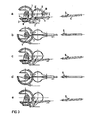
- FIG. 3a shows that the thread 2 runs over the thread guide 3 around the line bundle 1 and forms a loop 8 through which the latch needle is guided.
- the gripper 130 is in the starting position.
- the latch needle 4 is moved back with the tongue 9 open, the twine is taken along and pulled as a loop 7 through the last loop 8 present from the binding process.
- the link wheel 6 moves in the opposite direction, so that a position according to FIG. 3b results.
- the tongue 9 of the latch needle 4 is now closed, which can be achieved by the thread pressure if the latch needle 4 is designed accordingly.
- FIG. 3c the reverse movement sequence according to FIG. 3c, the tongue 9 opening when moving forward and the tongue needle 4 then moving through the newly formed loop into a position according to FIG. 3a.
- Corresponding substeps according to FIGS. 3d and 3e follow, which in principle correspond to the substeps according to FIGS. 3b and 3c, so that the result is a structure with several loops.
- the associated link guide is shown in detail: It consists essentially of a holding plate 11 with the guide groove 10 formed in two guide halves, a pin 12 for guiding the holding device 5 for the latch needle 4, a switching tongue 13, a locking lever 14 and a further pin 15. While during the binding process the holding of the latch needle 4 executes such a path, which is described in FIG. 4 by points 1 through 11 to III and from III to 11 to back to 1, path 11 becomes, for example, during the knotting process locked according to III. The pin 12 and the latch needle 4 thus follow the direct path from 1 to 11 and back again from II to I. The latter movement defines a loop which can be tightened to form a knot and can be repeated as required. The setting is blocked by the switching tongue 13, which is pressed upward by the locking lever 14, the locking lever 14 acting directly on the pin 15.
- the thread 2 of the twine is to be tightened and cut in a defined position, whereby it must be ensured that the cut thread can be caught and is thus immediately available for a new binding process.
- the kinematics of cutting off on the one hand and catching the thread end on the other hand will be explained in various working phases with reference to FIGS. 5 and 6 on the one hand and FIGS. 7 and 8 on the other hand.
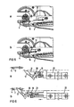
- 16 means the knot to be formed, 17 the cutting knife, 18 the catching needle, 19 the associated holder, 20 a pin on the knife holder, 21 an associated link for guiding the cutting knife 17 and catching needle 18, 22 a compressed air cylinder , 23 a clamping pin, 24 an elbow, 25 a spring, 26 a needle opening and 28 a stop for the catch needle 18th
- FIGS. 5b and 6b show their position immediately after the cutting process.
- the blade 17 is brought along the slide guide 21 into the plane of the latch needle 4, the thread being cut off directly at the knot 16.
- the catching needle 18 is present, the shape and function of which becomes clear in detail on the basis of FIGS. 7 and 8.
- the sectional view of FIG. 8a shows their comparatively complex structure with inner clamping pin 23, inner spring 25 and an outer pin 27 which is resiliently mounted via an angle piece 24.
- the clamping pin 23 is firmly connected to the angle 24 and is pressed forward by the spring 25 , so that a thread 2 can be firmly clamped in the needle opening 26.
- the inner spring pin 27 also serves to support the clamping process.
- 6b and 7b in particular illustrate the interaction of latch needle 4, cutting knife 17 and catch needle 18. After cutting, the end of thread 2 is clamped into opening 26 of needle 18. A stop 28 is used to return the clamping device 23 and 24, so that the needle opening 26 is free and the thread 2 can be caught. It is held in place during the subsequent backward movement of the catching needle 18.
- the latter can in one embodiment of the Er find in connection with a compressed air drive by a cam control, which is illustrated by the description of FIGS. 9 to 11.
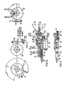
- the cam control is driven via the link wheel 6, which is rotated in a known manner during the forward and backward movement of the latch needle 4 to the left or right.
- a drive gear 29, which serves to drive an associated control gear 30, is fastened concentrically to the sliding gear 6. Its fixed axis 31 is screwed to the holding plate 11 of FIG. 4.
- a freewheel 32 is seated in the axis of the control gear 30, which only permits clockwise rotation of the switching disks 34, 35 and 36, which are jointly attached to a bushing 33.
- the gear ratio between the gear wheels 29 and 30 is selected such that a working cycle is completed when the switching disk 34, 35 and 36 is rotated through 360 °.
- This work cycle includes the tying, knotting, cutting and catching or holding process for the twine.
- the switching disk 34 has sawtooth-shaped notches on the circumference, which have an angular distance of 2x90 ° for a two-time binding process, an angular distance of 2x45 ° for a two-time knotting process and a further 90 ° for the zero position.
- a spring-loaded pawl 37 can snap into the notches. The pawl 37 is used for the exact fixing of the switching disks 34, 35 and 36 and thus prevents turning back when the directional gear 6 changes direction.
- the switching disk 35 in FIG. 11 1 is necessary for the knotting process if, as has been shown above, the blocking of the path 11 to 111 in the link guide 10 is to be effected in the angular range of 2 ⁇ 45 °.
- the switching disk 36 with pawl 39 is used to stop the binding device. A reversing slide can be blocked via the pawl 39 and the operating function of the device described can thus be stopped.
- the switching disk 34 carries a switching cam 40 which in each case triggers a separate control for the cutting and thread catching process when the winding gun is stopped.
- the drive and control takes place on a pneumatic / mechanical basis. It is also possible to provide the drive electrically and to create an electronic sequence control.
- a microprocessor system can expediently be used here.
Landscapes
- Engineering & Computer Science (AREA)
- Manufacturing & Machinery (AREA)
- Basic Packing Technique (AREA)
- Insertion, Bundling And Securing Of Wires For Electric Apparatuses (AREA)
Abstract
Description
Die Erfindung bezieht sich auf eine Vorrichtung zum Binden eines Bündels elektrischer Leitungen gemäss dem Oberbegriff des Patentanspruches 1.The invention relates to a device for binding a bundle of electrical lines according to the preamble of claim 1.
Auf vielen Gebieten der Technik besteht die Forderung, mehrere elektrische Leitungen zusammenzubinden. Beispielsweise müssen bei elektrischen Ausrüstungen Kabelbäume mit über längere Strecken parallel geführten Leitungen oder Motoren-Wickelköpfe mit Leitungsbündeln fixiert werden. Es ist bekannt, jeweils mit separaten Kunststoff-Kabelbindem, welche jede einen Einzelverschluss haben, Bündel von Leitungen zusammenzuhalten. Dafür werden spezielle Kabelbinder benötigt, die als Kunststoffteile vorgefertigt und vergleichsweise teuer sind. Es wurden auch bereits Verfahren und Vorrichtungen vorgeschlagen, mit denen Kabelbäume od. dgl. gebunden werden können. Dabei wird der Kabelbaum maschinell von einem als Wickeleinrichtung bezeichneten Gerät nach Art eines Häkelvorganges fortlaufend mit in Schleifen gelegten Bindegarn umschlungen; bei Beendigung des Bindevorganges wird das Fadenende manuell abgetrennt und verknotet.In many areas of technology, there is a requirement to bind several electrical lines together. For example, in the case of electrical equipment, cable harnesses with cables routed in parallel over long distances or motor winding heads must be fixed with cable bundles. It is known to hold bundles of lines together with separate plastic cable ties, each of which has an individual closure. This requires special cable ties, which are prefabricated as plastic parts and are comparatively expensive. Methods and devices with which cable harnesses or the like can be bound have also already been proposed. The cable harness is continuously wrapped mechanically by a device called a winding device in the manner of a crochet process with twine laid in loops; at the end of the binding process, the end of the thread is manually separated and knotted.
Letzteres Verfahren wird im einzelnen in der DE-A-25 33 640 beschrieben. Mit einem derart ausgebildeten Gerät ist es insbesondere möglich, einen Kabelbaum maschinell und kontinuierlich zu umwikkein, wobei durch einen jeweils doppelt geführten Faden bei der Schleifenbildung eine Stabilität des geschaffenen Fadengebindes erreicht werden soll. Nicht möglich mit diesem Gerät ist aber ein Verknoten und Abschneiden des Bindegarns, so dass ein vollautomatischer Betrieb noch nicht erreicht wird. Letztere Eigenart des aus der DE-A-25 33 640 vorbekannten Gerätes wird von der Fachwelt als nachteilig angesehen, da ein praxisgerechtes Arbeiten nicht realisierbar ist.The latter method is described in detail in DE-A-25 33 640. With a device designed in this way, it is in particular possible to machine a wire harness continuously and continuously, the stability of the thread bundle created should be achieved by means of a double thread in each case during the loop formation. Knotting and cutting off the twine is not possible with this device, so that fully automatic operation is not yet achieved. The latter peculiarity of the device previously known from DE-A-25 33 640 is regarded by the experts as disadvantageous since practical work cannot be carried out.
Darüber hinaus ist aus der DE-A-2705418 ein automatischer Binder zum Binden eines Gegenstandes mit einem langen, flexiblen Bindematerial bekannt, der jeweils eine Führungseinrichtung, eine Fördereinrichtung, eine Festzieheinrichtung und eine Greifeinrichtung für das flexible Material aufweist. Damit sollen Schlaufen des Materials, das aus einer Nylonlitze mit Eigensteifigkeit besteht, um ein Leitungsbündel gelegt werden, die anschliessend festgezogen werden. Zusätzlich ist eine Schneideinrichtung als mechanisches Bauteil mit zwei Messern zum Abschneiden der Enden des flexiblen Materials nach dem Festziehen und eine Antriebs- und Steuereinrichtung vorhanden. Insbesondere die Führungseinrichtung und die Greifeinrichtung werden von einem reversiblen Motor aktiviert, während ansonsten ein druckluftbetriebener Zylindermechanismus vorhanden ist. Das Festziehen der Nylonlitze als flexibles Material erfolgt in einem primären und einem sekundären Verfahrensschritt, wobei dazwischen ein Rollenmechanismus relativ zum Binder bewegt werden muss. Der Gesamtaufbau ist dadurch vergleichsweise kompliziert.In addition, from DE-A-2705418 an automatic binder for binding an object with a long, flexible binding material is known, each having a guide device, a conveyor, a tightening device and a gripping device for the flexible material. The purpose of this is to place loops of the material, which consists of a nylon strand with inherent rigidity, around a bundle of lines, which are then tightened. In addition, there is a cutting device as a mechanical component with two knives for cutting off the ends of the flexible material after tightening, and a drive and control device. In particular, the guide device and the gripping device are activated by a reversible motor, while a cylinder mechanism operated by compressed air is otherwise present. The tightening of the nylon strand as a flexible material takes place in a primary and a secondary process step, in between which a roller mechanism has to be moved relative to the binder. The overall structure is comparatively complicated.
Aufgabe der Erfindung ist es demgegenüber eine Vorrichtung zu schaffen, die mit einem beliebigen Faden arbeiten kann und einfach aufgebaut ist. Beispielsweise für das Binden von Motoren-Wickelköpfen soll diese Vorrichtung im vollautomatischen Betrieb einsetzbar sein. Daneben soll die neue Vorrichtung insbesondere im Einhandbetrieb verwendbar sein, ohne dass zwischenzeitlich oder anschliessend weitere manuell durchzuführende Verfahrensschritte notwendig werden.In contrast, the object of the invention is to provide a device which can work with any thread and is simple in construction. For example, for binding motor winding heads, this device should be able to be used in fully automatic operation. In addition, the new device should be usable, in particular, in one-hand operation, without any additional manual steps which have to be carried out in the meantime or subsequently.
Die Aufgabe ist erfindungsgemäss durch die kennzeichnenden Merkmale des Patentanspruches 1 gelöst.According to the invention, the object is achieved by the characterizing features of patent claim 1.
Vorteilhafte Weiterbildungen sind in den Unteransprüchen angegeben.Advantageous further developments are specified in the subclaims.
Mit der Erfindung ist eine praxisgerechte Vorrichtung geschaffen. Ein gemäss der neuen Vorrichtung realisiertes Gerät kann während des gesamten Arbeitsablaufes wie eine Pistole von einer Bedienperson mit einer Hand gehalten werden und mit seinem Greifer jeweils zur gewünschten Bindestelle geführt werden. Da das realisierte Bindeverfahren wie bei der DE-A-2705418 diskontinuierlich arbeitet, aber einerseits nach Umschlingen und Knoten das rückseitige Fadenende des Bindegarns abgeschnitten, andererseits aber das fortlaufende Ende des Bindegarns aufgefangen wird, kann ein von einer Spule abwickelbarer Faden verwendet werden. Trotzdem jeweils punktuell ein Abbinden erfolgen, wozu das Gerät frei zum Kabelbaum führbar ist.The invention creates a practical device. A device implemented according to the new device can be held like a pistol by an operator with one hand during the entire workflow and can be guided with its gripper to the desired binding point. Since the binding method implemented as in DE-A-2705418 works discontinuously, but on the one hand the loop end of the twine is cut off after looping and knotting, but on the other hand the continuous end of the twine is caught, a thread that can be unwound from a bobbin can be used. Nevertheless, binding takes place at certain points, for which the device can be freely guided to the wiring harness.
Bei der erfindungsgemässen Vorrichtung wird neben der Zungennadel ein Schneidmesser und eine Fangnadel so geführt, dass in zeitlicher Aufeinanderfolge zuerst das Umschlingen und Knoten mit der Zungennadel und anschliessend das Abschneiden und Auffangen erfolgt. Dabei bilden das Binden, Knoten, Schneiden und Fangen des Fadens einen einzigen abgeschlossenen Arbeitszyklus. Vorzugsweise erfolgt der Antrieb druckluftgesteuert und ist die Steuerung mechanisch aufgebaut. Es ist aber auch eine elektrisch/elektronische Antriebssteuerung möglich.In the device according to the invention, in addition to the latch needle, a cutting knife and a catching needle are guided in such a way that, in chronological succession, the looping and knotting with the latch needle is carried out first, followed by cutting and catching. The tying, knotting, cutting and catching of the thread form a single, completed work cycle. The drive is preferably controlled by compressed air and the control is constructed mechanically. However, an electrical / electronic drive control is also possible.
Weitere Einzelheiten und Vorteile einer Ausführungsform der Erfindung ergeben sich aus nachfolgender Figurenbeschreibung eines Ausführungsbeispiels anhand der Zeichnung in Verbindung mit den abhängigen Patentansprüchen.Further details and advantages of an embodiment of the invention result from the following description of the figures of an embodiment with reference to the drawing in conjunction with the dependent claims.
Es zeigen
- Fig. 1 und Fig. 2 den schematischen Aufbau der Gesamtvorrichtung in teilweise geschnittener Ansicht und Draufsicht,
- Fig. 3 einen Teilausschnitt der Fig. 1 in verschiedenen Arbeitsphasen zur Verdeutlichung der Kinematik des Knotvorganges,
- Fig. 4 in Seitenansicht die Führungskulisse für die Zungennadel mit Einstellglied für den Knotvorgang,
- Fig. 5 und Fig. 6 einen Ausschnitt aus den Figuren 1 und 2 in verschiedenen Arbeitsphasen zur Verdeutlichung des Schneidvorganges,
- Fig. 7 und Fig. 8 einen Ausschnitt aus den Figuren 1 und 2 in verschiedenen Arbeitsphasen zur Verdeutlichung des Fangvorganges,
- Fig. 9 und Fig. 10 das verwendete Steuergetriebe in Seitenansicht und Draufsicht,
- Fig. 11 die zur Steuerung des Arbeitszyklus verwendeten Getriebescheiben sowie
- Fig. 12 und Fig. 13 die Einheit zur Druckluftsteuerung in Seitenansicht und Draufsicht.
- 1 and Fig. 2 shows the schematic structure of the overall device in a partially sectioned view and top view,
- 3 shows a partial section of FIG. 1 in different work phases to illustrate the kinematics of the knotting process,
- 4 is a side view of the guide link for the latch needle with an adjusting member for the knotting process,
- 5 and FIG. 6 shows a detail from FIGS. 1 and 2 in different working phases to illustrate the cutting process,
- 7 and FIG. 8 a section from FIGS. 1 and 2 in different working phases to illustrate the catching process,
- 9 and Fig. 10, the control gear used in side view and top view,
- Fig. 11, the gear discs used to control the work cycle and
- Fig. 12 and Fig. 13, the unit for compressed air control in side view and top view.
Die Figuren geben jeweils Teilbereiche der gesamten Vorrichtung wieder; sie sind nicht massstäblich zueinander dargestellt. In der Figurenbeschreibung wird durchweg nur auf die erfindungswesentlichen Einzelheiten eingangen.The figures show partial areas of the entire device; they are not drawn to one another to scale. In the description of the figures, only the details essential to the invention are discussed.
In den einzelnen Figuren sind identische Teile mit den gleichen Bezugszeichen versehen. Bei der Beschreibung wird verschiedentlich auf die DE-A-2533640 Bezug genommen, in der der eigentliche Bindevorgang bereits so deutlich beschrieben ist, dass darauf nachfolgend nicht mehr im einzelnen eingegangen wird.Identical parts are provided with the same reference symbols in the individual figures. In the description, various references are made to DE-A-2533640, in which the actual binding process is already described so clearly that it will not be discussed in detail below.
In Fig. 1 und Fig. 2 kennzeichnet 100 das Gehäuse einer Vorrichtung zum Umbinden von parallelen Leitungen, wie beispielsweise Kabelbäumen oder dergleichen, die nachfolgend als Wickelpistole bezeichnet wird. Durch die Bezeichnung «Wickelpistole» wird bereits deutlich, dass das Gehäuse vom Benutzer mittels einer Hand an einem Gehäuseknauf 105 gehalten, in die richtige Arbeitsposition gebracht und über einen Betätigungshebel 106 in Betrieb gesetzt werden kann. Dabei ist die gesamte Wickelpistole so kompakt aufgebaut, dass sie auch bei beengten Arbeitsverhältnissen ohne Schwierigkeiten in die jeweilige Betriebsposition bringbar ist. Es ist möglich, die Wickelpistole manuell oder maschinell, insbesondere robotergeführt, an einem Kabelbaum entlang zu führen.1 and 2, 100 denotes the housing of a device for tying parallel lines, such as cable harnesses or the like, which is referred to below as a winding gun. The term “winding gun” already makes it clear that the housing can be held by the user on a
Das Gehäuse 100 der Wickelpistole besteht im wesentlichen aus zwei parallelen mit Abstand verbundenen Gehäuseplatten 110 und 111, an welchen die Arbeitsgerätschaften und die dazu notwendigen Betriebsmittel angeordnet sind. Rückwärtig kann eine Vorratsrolle für Bindegarn angeordnet sein, von der ein Faden 2 über entsprechende Führungen in den Arbeitsbereich am vorderen Teil des Gehäuses 100 gebracht wird. Eine Fadenspann- und Rückholeinrichtung 120 sorgt für die notwendige Spannung im Faden. Der Arbeitsbereich ist mit einer Führung 3 für den Faden 2 und einem Greifer 130 derart ausgebildet, dass ein Bündel paralleler Leitungen vom Faden 2 umschlungen werden kann. Dabei ist der Greifer 130 in etwa hufeisenförmig geformt und wird von einem Zahnradgetriebe geführt. Er kann jeweils um etwa ± 90° verschwenkt werden, um ein Umschlingen eines mit seinem Querschnitt im Hufeisenprofil liegenden Kabelbaums zu gewährleisten. Dabei kommt es beim Umschlingen auf das Zusammenspiel des Greifers 130 mit Fadenführung 3 und einer zugehörigen Haltenadel 4 für den Faden an, was noch im einzelnen beschrieben wird. Die Nadel 4 wird wegen einer Mitnehmerzunge 9 für den Faden 2 als «Zungennadel» bezeichnet. Über eine zugehörige Halterung 5 und Antrieb 140 mit Druckluftzylinder ist eine Vor- und Rückwärtsbewegung der Zungennadel 4 möglich. Dabei ist die Halterung 5 der Zungennadel 4 gleichermassen kulissengeführt, so dass neben der übergeordneten Vor- und Rückwärtsbewegung auch eine Bewegung in vorbestimmter Kurvenform erfolgt.The
Bei der Bewegung der Zungennadel 4 zum Umschlingen eines Kabelbaums bzw. von Parallelleitungen mit Bindegarn ist es wichtig, dass der Faden 2 im Arbeitsbereich definiert geführt ist. Dazu sind im Bereich des Greifers 130 an den Gehäuseplatten 110 und 111 entsprechende Führungsbleche 131 und 132 vorhanden.When moving the
Die aus Fig. 1 entnehmbare Grundform der Wickelpistole ist im wesentlichen aus der DE-A-2533640 bekannt. In dieser Druckschrift wird das Zusammenwirken von Zungennadel 4 und Greifer 130 im einzelnen beschrieben, wobei dort fortlaufend Schleifen zum Umschlingen der Parallelleitungen gebildet werden. Nach Beendigung der Umschlingungsvorgänge zur Bildung eines Geflechtes entlang dem ausgedehnten Kabelbaum muss dort das Bindegarn abgeschnitten und das Fadenende manuell verknotet werden.The basic shape of the winding gun, which can be seen in FIG. 1, is essentially known from DE-A-2533640. In this publication, the interaction of
Aus Fig. 2 ist ersichtlich, dass die Wickelpistole gemäss vorliegender Patentanmeldung zusätzliche Arbeitsgerätschaften aufweist, die seitlich an der Gehäuseplatte 111 angebracht sind. Dies sind im wesentlichen ein Schneidmesser 17 und eine sogenannte Fangnadel 18, welche beide über einen Antrieb 160 mit Druckzylinder ebenfalls eine Vor- und Rückwärtsbewegung ausführen können. Dabei erfolgt die Bewegung zwar in Richtung auf die Gehäuseplatte 111 kulissengeführt, was aus dem dargestellten Nutprofil erkennbar ist.From Fig. 2 it can be seen that the winding gun according to the present patent application has additional equipment that is attached to the side of the
Die druckmittelbetätigten Antriebseinheiten 140 und 160 sind miteinander im Sinne einer Zeitverzögerung des Bewegungsablaufes gekoppelt, was weiter unten noch erläutert wird.The pressure medium-actuated
Mit dem Schneidmesser 17 und der Fangnadel 18 und den zugehörigen Betriebs- bzw. Steuermitteln ist es nun möglich, den Umschlingungsvorgang, der bisher kontinuierlich entlang eines Kabelbaumes durchgeführt wurde, vollautomatisch diskontinuierlich einschliesslich jeweiligem Verknoten und Abschneiden durchzuführen, so dass nun mehr punktuell gebunden werden kann. Zweckmässigerweise wird dabei das Binden auf ein zweimaliges Umschlingen begrenzt, was bereits eine hinreichende Wickelfestigkeit gewährleistet, wodurch neben der Verringerung des Arbeitsaufwandes auch eine erhebliche Materialeinsparung erreichbar ist.With the cutting
Ausgehend vom bekannten Bindevorgang werden nun anhand der Fig. 3 sowie der Fig. 5, 6 und Fig. 7, 8 die Vorgänge des Knotens, Abschneidens und Auffangens des Fadenendes in ihrer Kinematik erläutert. Dabei kennzeichnen jeweils die Teilfiguren a, b, ... eine signifikante Phase des entsprechenden Vorganges. Zusammen ergeben diese Teilvorgänge einen kompletten Arbeitszyklus.Based on the known binding process, the kinematics of the knotting, cutting and catching of the thread end will now be explained with reference to FIGS. 3 and 5, 6 and 7, 8. Sub-figures a, b, ... each indicate a significant phase of the corresponding process. Together, these sub-operations result in a complete work cycle.
In Fig. 3 stellt 1 ein bereits gebundenes Leiterbündel dar. Daneben kennzeichnen 2 das Bindegarn, 3 eine Fadenführeinrichtung, 4 die Zungennadel, 5 die zugehörige Halterung, 6 das Kulissenrad und 10 die zugehörige Kulissenführung. Die Zuordnung dieser Einzelheiten zur Fig. 1 ist deutlich erkennbar. Bei den einzelnen Phasen des Knotvorganges ist jeweils zur Zungennadel 4 die Stellung der zugehörigen Zunge 9 angegeben.In FIG. 3, 1 represents an already bound conductor bundle. In addition, 2 identify the binding twine, 3 a thread guide device, 4 the latch needle, 5 the associated holder, 6 the link wheel and 10 the associated link guide. The assignment of these details to FIG. 1 is clearly recognizable. In the individual phases of the knotting process, the position of the associated
Die dargestellte Vorrichtung dient zunächst in an sich bekannter Weise zum Binden eines Kabelbaumes. Dabei wird - wie im einzelnen in der DE-A-2533640 beschrieben - die Halterung 5 abwechselnd in der unteren oder oberen Nut der Kulissenführung 10 hin- und hergeschoben, wobei sich im Zusammenwirken mit dem Greifer 130 die Umschlingung des Kabelbaums mit dem Faden 2 ergibt. Für das Knoten wird die obere Führungshälfte der Kulissenführung 10 gesperrt, so dass die Zungennadel 4 sich nunmehr nur noch in der Nut der unteren Führungshälfte hin- und herbewegen kann.The device shown is initially used in a manner known per se for tying a wire harness. Here - as described in detail in DE-A-2533640 - the
In Fig. 3a ist gezeigt, dass der Faden 2 über die Fadenführung 3 um das Leitungsbündel 1 herumläuft und eine Schlaufe 8 bildet, durch die die Zungennadel geführt ist. Der Greifer 130 befindet sich dabei in der Ausgangslage. Beim Zurückbewegen der Zungennadel 4 wird bei offener Zunge 9 das Bindegarn mitgenommen und als Schlaufe 7 durch die vom Bindevorgang vorhandene letzte Schlaufe 8 gezogen. Gleichzeitig bewegt sich das Kulissenrad 6 in entgegengesetzte Richtung, so dass sich eine Position gemäss Fig. 3b ergibt. Die Zunge 9 der Zungennadel 4 ist nun geschlossen, was sich bei entsprechender Ausbildung der Zungennadel 4 durch den Fadendruck erreichen lässt. Es schliesst sich darauf der umgekehrte Bewegungsablauf gemäss Fig. 3c an, wobei sich beim Vorwärtsbewegen die Zunge 9 öffnet und die Zungennadel 4 anschliessend durch die neugebildete Schlaufe in eine Position gemäss Fig. 3a fährt. Entsprechende Teilschritte gemäss Fig. 3d und Fig. 3e folgen, die prinzipiell den Teilschritten gemäss Fig. 3b und Fig. 3c entsprechen, so dass im Ergebnis ein Gebilde mit mehreren Schleifen vorliegt.3a shows that the
Es wurde bereits erwähnt, dass für den Knotvorgang die identische Gerätschaft aus Greifer 130 und Zungennadel 4 wie für den Bindevorgang notwendig ist. Einziger Unterschied ist die spezielle Bewegung der Zungennadel 4, die beim Binden abwechselnd oberhalb und unterhalb des Bündels 1 geführt wird, während für das Knoten eine durchgehend gleiche Bewegung erfolgt. Dafür ist eine umschaltbare Kulisse notwendig.It has already been mentioned that for the knotting process the identical equipment of
In Fig. 4 ist die zugehörige Kulissenführung im einzelnen dargestellt: Sie besteht im wesentlichen aus einem Halteblech 11 mit der in zwei Führungshälften ausgebildeten Kulissennut 10, einem Zapfen 12 zur Führung der Halteeinrichtung 5 für die Zungennadel 4, einer Umschaltzunge 13, einem Sperrhebel 14 und einem weiteren Zapfen 15. Während beim Bindevorgang die Halterung der Zungennadel 4 einen solchen Weg ausführt, der in Fig. 4 durch die Punkte 1 über 11 nach III und von III nach 11 bis zurück nach 1 beschrieben ist, wird beim Knotvorgang beispielsweise der Weg 11 nach III gesperrt. Damit folgen der Zapfen 12 und die Zungennadel 4 dem direkten Weg von 1 nach 11 und wieder zurück von II nach I. Letztere Bewegung definiert jeweils eine zu einem Knoten festziehbare Schleife und kann beliebig wiederholt werden. Die Sperrung der Kulisse erfolgt durch die Umschaltzunge 13, welche durch den Sperrhebel 14 nach oben gedrückt wird, wobei der Sperrhebel 14 direkt auf den Zapfen 15 einwirkt.In Fig. 4, the associated link guide is shown in detail: It consists essentially of a holding
Nach dem Legen von Knotenschleifen ist der Faden 2 des Bindegarns festzuziehen und in definierter Lage abzuschneiden, wobei sichergestellt sein muss, dass der abgeschnittene Faden gefangen werden kann und so unmittelbar für einen neuen Bindevorgang zur Verfügung steht. Die Kinematik des Abschneidens einerseits und des Fangens des Fadenendes andererseits wird anhand der Fig. 5 und 6 einerseits sowie Fig. 7 und 8 andererseits in verschiedenen Arbeitsphasen erläutert.After the knot loops have been laid, the
In Fig. 5 bis 8 bedeuten 16 der zu bildende Knoten, 17 das Schneidmesser, 18 die Fangnadel, 19 die zugehörige Halterung, 20 ein Zapfen an der Messerhalterung, 21 eine zugehörige Kulisse für die Führung von Schneidmesser 17 und Fangnadel 18, 22 ein Druckluftzylinder, 23 ein Klemmstift, 24 ein Winkelstück, 25 eine Feder, 26 eine Nadelöffnung und 28 ein Anschlag für die Fangnadel 18.In FIGS. 5 to 8, 16 means the knot to be formed, 17 the cutting knife, 18 the catching needle, 19 the associated holder, 20 a pin on the knife holder, 21 an associated link for guiding the cutting
Wesentlich ist, dass das Schneidmesser 17 und die Fangnadel 18 an der gemeinsam geführten Halterung 19 angebracht sind und aufeinander in ihrem Bewegungsablauf abgestimmt sind. Die gelenkig gelagerte Halterung 19 mit Schneidmesser 17 und Fangnadel 18 wird durch den Druckluftzylinder 22 synchron bewegt.It is essential that the cutting
Während sich das Schneidmesser 17 in Fig. 5a und Fig. 6a in seiner Ruhestellung befindet, ist in Fig. 5b und Fig. 6b dessen Stellung unmittelbar nach dem Schneidvorgang gezeigt. Es ist ersichtlich, dass dazu die Klinge 17 entlang der Kulissenführung 21 in die Ebene der Zungennadel 4 gebracht wird, wobei das Abschneiden des Fadens unmittelbar am Knoten 16 erfolgt. Dabei ist es zweckmässig das freie Ende durch das Knotengebilde 16 rückwärts hindurchzuziehen, wodurch das Auffangen des Fadenendes vereinfacht wird. Dazu ist die Fangnadel 18 vorhanden, deren Form und Funktion im einzelnen anhand Fig. 7 und Fig. 8 deutlich wird. Insbesondere aus der Schnittdarstellung der Fig. 8a ergibt sich deren vergleichsweise komplexer Aufbau mit Innenklemmstift 23, Innenfeder 25 und über ein Winkelstück 24 federnd gelagerten Aussenstift 27. Dabei ist der Klemmstift 23 mit dem Winkel 24 fest verbunden und wird durch die Feder 25 nach vorn gedrückt, so dass in der Nadelöffnung 26 ein Faden 2 fest einklemmbar ist. Der Innenfederstift 27 dient gleichermassen zur Unterstützung des Klemmvorganges.5a and 6a are in their rest position, FIGS. 5b and 6b show their position immediately after the cutting process. It can be seen that for this purpose the
Durch das Zusammenwirken von Schneidmesser 17 und Fangnadel 18 ist es nunmehr auch überflüssig, bei Beginn des Bindevorganges den Faden festzuhalten, wie es bei Geräten des Standes derTechnik notwendig war. Damit ergibt sich jetzt erstmalig die Möglichkeit eines vollautomatischen Arbeitsablaufes. Insbesondere Fig. 6b und Fig. 7b verdeutlichen das Zusammenwirken von Zungennadel 4, Schneidmesser 17 und Fangnadel 18. Nach dem Abschneiden wird das Ende des Fadens 2 in die Öffnung 26 der Nadel 18 eingeklemmt. Zum Zurückbringen der Klemmvorrichtung 23 und 24 dient ein Anschlag 28, so dass die Nadelöffnung 26 frei wird und der Faden 2 gefangen werden kann. Er wird bei der sich anschliessenden Rückwärtsbewegung der Fangnadel 18 festgehalten.Due to the interaction of the cutting
Aus den vorangehenden Einzelbeschreibungen der Gerätschaften für das Knoten, Abschneiden und Auffangen des Fadens ergab sich deutlich, dass die Bewegungsabläufe beim Binden, Knoten, Abschneiden, Fangen und Halten des Bindegarns zeitlich exakt aufeinander abgestimmt sein müssen. Hierzu sind neben dem Antrieb geeignete Steuermittel notwendig.From the preceding individual descriptions of the equipment for knotting, cutting and catching the thread, it clearly emerged that the movement sequences for tying, knotting, cutting, catching and holding the twine must be precisely coordinated with one another in terms of time. Suitable control means are necessary in addition to the drive.
Letzteres kann bei einer Ausführungsform der Erfindung in Verbindung mit einem Druckluftantrieb durch eine Nockensteuerung geschehen, welche anhand der Beschreibung von Fig. 9 bis Fig. 11 verdeutlicht wird. Der Antrieb der Nockensteuerung erfolgt über das Kulissenrad 6, das in bekannter Weise bei der Vor- und Rückwärtsbewegung der Zungennadel 4 nach links bzw. rechts verdreht wird. Konzentrisch zum Kulissenrad 6 ist ein Antriebszahnrad 29 befestigt, welches zum Antrieb eines zugeordneten Steuerzahnrades 30 dient. Dessen feststehende Achse 31 ist an das Halteblech 11 der Fig. 4 angeschraubt. In der Achse des Steuerzahnrades 30 sitzt ein Freilauf 32, der nur eine Rechtsdrehung von gemeinsam auf einer Buchse 33 befestigten Schaltscheiben 34, 35 und 36 zulässt. Die Übersetzung zwischen den Zahnrädern 29 und 30 ist so gewählt, dass bei einer Drehung der Schaltscheibe 34, 35 und 36 um 360° ein Arbeitszyklus abgeschlossen ist. Dieser Arbeitszyklus beinhaltet den Binde-, Knot-, Schneid- und Fang- bzw. Haltevorgang für das Bindegarn.The latter can in one embodiment of the Er find in connection with a compressed air drive by a cam control, which is illustrated by the description of FIGS. 9 to 11. The cam control is driven via the link wheel 6, which is rotated in a known manner during the forward and backward movement of the
Aus Fig. 11 ist ersichtlich, dass die Schaltscheibe 34 am Umfang sägezahnförmige Kerben, die einen Winkelabstand von 2x90° für einen zweimaligen Bindevorgang, einen Winkelabstand von 2x45° für einen zweimaligen Knotenvorgang und weitere 90° für die Nullstellung besitzen. In die Kerben kann eine gefedert gelagerte Sperrklinke 37 einrasten. Die Sperrklinke 37 dient zur exakten Fixierung der Schaltscheiben 34, 35 und 36 und verhindert damit das Zurückdrehen bei der Richtungsänderung des Kulissenzahnrades 6.From Fig. 11 it can be seen that the
Die Schaltscheibe 35 in Fig. 11 1 ist für den Knotvorgang deswegen erforderlich, wenn wie oben gezeigt wurde im Winkelbereich von 2x45° die Sperrung des Weges 11 nach 111 in der Kulissenführung 10 bewirkt werden soll. Dazu dient die Sperre 14, die an einem Hebel 38 befestigt ist. Die Schaltscheibe 36 mit Klinke 39 dient dagegen zum Stillsetzen des Bindegerätes. Über die Klinke 39 kann ein Umsteuerschieber blockiert und damit die Betriebsfunktion der beschriebenen Vorrichtung gestoppt werden.The
Aus Fig. 9 und Fig. 10 ist ersichtlich, dass die Schaltscheibe 34 eine Schaltnocke 40 trägt, die jeweils dann eine separate Ansteuerung für den Schneide- und Fadenfang-Vorgang auslöst, wenn die Wickelpistole stillgesetzt wird.From FIG. 9 and FIG. 10 it can be seen that the
Die Schaltscheibe 34 mit Schaltnocke 40 steht mit der Druckluftsteuerung gemäss Fig. 12 und Fig. 13 in unmittelbarer Wirkverbindung. In letzteren Figuren bedeuten 41 ein zeitverzögernder Luftdämpfer, 42 ein Steuerventil, 43 ein Stift mit daran gelagerten Hebel 44, 45 ein weiterer Schaltarm, 46 eine Zugfeder, 47 ein Gelenk mit auf dem Hebel 44 federnd gelagerter Schaltklinke. Weiterhin kennzeichnen 50 ein am Punkt 49 gelagerter Hebel mit einer Schaltnocke 51, 52 einen Steuerkolben am Steuerventil 42, sowie 53 eine Druckfeder und 54 bis 56 Druckluftanschlüsse. Diese angegebenen Einzelheiten wirken folgendermassen zusammen und bilden eine Funktionseinheit:
- Bei
Bewegung der Schaltnocke 40 nach oben wird gleichzeitig dieSchaltklinke 44 nach unten und der Luftdämpfer 41 in Pfeilrichtung betätigt. Nachdem dieSchaltnocke 40den Hebel 44 passiert hat, bewegt sich dieSchaltklinke 48 zeitverzögert aufgrund des Luftdämpfers 41 nach oben und betätigt überden Hebel 50den Steuerkolben 52 nach rechts gegen dieDruckfeder 53. Dabei wird derAnschluss 56 mit Druckluft beaufschlagt, dermit dem Druckluftzylinder 22 in der Fig. 6 verbunden ist. Dadurch wird die Vorwärtsbewegung des Schneidmessers 17 und der Fangnadel 18 eingeleitet. Wenn die Schaltklinke 48 über dieNocke 51 läuft, bewegt sich der Steuerkolben 52 aufgrund der Druckfeder 53 nach links.Der Druckluftanschluss 55 wird dann mit Druckluft beaufschlagt und leitet überden Zylinder 22 die Rückstellbewegung desMessers 17 und der Fangnadel 18 ein.
- When the switching
cam 40 moves upwards, the switchingpawl 44 and theair damper 41 are simultaneously actuated in the direction of the arrow. After theswitching cam 40 has passed thelever 44, the switchingpawl 48 moves upwards with a time delay due to theair damper 41 and actuates thecontrol piston 52 to the right against thecompression spring 53 via thelever 50Air cylinder 22 is connected in FIG. 6. This initiates the forward movement of the cuttingknife 17 and thecatch needle 18. When thepawl 48 runs over thecam 51, thecontrol piston 52 moves due to thecompression spring 53 to the left. Thecompressed air connection 55 is then pressurized with compressed air and initiates the return movement of theknife 17 and the catchingneedle 18 via thecylinder 22.
Damit ist ein Arbeitszyklus aus Binden, Knoten, Abschneiden und Auffangen des Fadens abgeschlossen. Die Vorrichtung ist für einen erneuten Arbeitszyklus betriebsbereit.This completes a work cycle of tying, knotting, cutting and catching the thread. The device is ready for another cycle.
Bei der oben beschriebenen Vorrichtung mit den verschiedenen Gerätschaften ist als wesentlich hervorzuheben, dass der Arbeitszyklus von Binden, Knoten, Abschneiden und Auffangen des Fadens erstmalig in zeitlich exakt aufeinander abgestimmten Einzelschritten durchgeführt wird. Dabei sind Binde-und Knotvorgang einerseits sowie Schneid- und Auffangvorgang andererseits jeweils gleichwirkend und voneinander deutlich getrennt.In the device with the various devices described above, it should be emphasized as essential that the work cycle of tying, knotting, cutting and catching the thread is carried out for the first time in individual steps that are precisely coordinated with one another in terms of time. The binding and knotting process, on the one hand, and the cutting and catching process, on the other hand, each have the same effect and are clearly separated from one another.
Beim beschriebenen Ausführungsbeispiel erfolgt Antrieb und Steuerung auf pneumatisch/mechanischer Basis. Es ist auch möglich, den Antrieb elektrisch vorzusehen und dazu eine elektronische Ablaufsteuerung zu schaffen. Dabei kann zweckmässigerweise von einem Mikroprozessorsystem Gebrauch gemacht werden.In the exemplary embodiment described, the drive and control takes place on a pneumatic / mechanical basis. It is also possible to provide the drive electrically and to create an electronic sequence control. A microprocessor system can expediently be used here.
Claims (9)
Priority Applications (1)
| Application Number | Priority Date | Filing Date | Title |
|---|---|---|---|
| AT84111771T ATE29797T1 (en) | 1983-10-18 | 1984-10-02 | DEVICE FOR TYING A BUNDLE OF ELECTRICAL WIRE. |
Applications Claiming Priority (2)
| Application Number | Priority Date | Filing Date | Title |
|---|---|---|---|
| DE3337853 | 1983-10-18 | ||
| DE19833337853 DE3337853A1 (en) | 1983-10-18 | 1983-10-18 | METHOD FOR BINDING A BUNDLE OF ELECTRICAL CABLES AND RELATED DEVICE |
Publications (2)
| Publication Number | Publication Date |
|---|---|
| EP0142001A1 EP0142001A1 (en) | 1985-05-22 |
| EP0142001B1 true EP0142001B1 (en) | 1987-09-16 |
Family
ID=6212129
Family Applications (1)
| Application Number | Title | Priority Date | Filing Date |
|---|---|---|---|
| EP84111771A Expired EP0142001B1 (en) | 1983-10-18 | 1984-10-02 | Device for tying a bundle of electrical leads |
Country Status (4)
| Country | Link |
|---|---|
| US (1) | US4558894A (en) |
| EP (1) | EP0142001B1 (en) |
| AT (1) | ATE29797T1 (en) |
| DE (2) | DE3337853A1 (en) |
Families Citing this family (16)
| Publication number | Priority date | Publication date | Assignee | Title |
|---|---|---|---|---|
| DE8602386U1 (en) * | 1986-01-30 | 1986-11-06 | Fraunhofer-Gesellschaft zur Förderung der angewandten Forschung e.V., 8000 München | Tool for tying off wiring harnesses |
| MY130074A (en) * | 1992-02-28 | 2007-05-31 | Bentac Co Ltd | Method and apparatus for tying one more articles |
| GB2317188B (en) | 1996-09-14 | 2000-06-14 | Bentley Harris Sa | Wiring harness bundling |
| US6944932B2 (en) * | 1999-08-27 | 2005-09-20 | Giovanni Fortuna | Method for making a self-locking knot in a stator lacing machine |
| ATE237191T1 (en) * | 1999-09-06 | 2003-04-15 | Giovanni Fortuna | METHOD AND DEVICE FOR PRODUCING A SELF-LOCKING KNOT IN A STATOR TYING MACHINE |
| US6279970B1 (en) | 2000-06-20 | 2001-08-28 | Michael Torres | Automatic knot-tying device |
| US6648378B1 (en) | 2002-10-04 | 2003-11-18 | Via Science Llc | Automatic knot-tying device |
| KR100804960B1 (en) * | 2007-03-29 | 2008-02-20 | 이덕희 | Replacement devices for knots in tack attachers |
| ATE549914T1 (en) | 2009-05-06 | 2012-04-15 | Qimas E U | PORTABLE BINDING MACHINE |
| US8622440B2 (en) * | 2010-10-05 | 2014-01-07 | Ideal Industries, Inc. | Knot tying device and cartridge system for providing tying filament thereto |
| US9433198B2 (en) * | 2014-03-06 | 2016-09-06 | Phyllis D. O'Neal | Fishing line knotter |
| WO2015162595A1 (en) | 2014-04-24 | 2015-10-29 | Cruzzolin Andrea | Apparatus and corresponding operative method to automatically bind at least two elements to each other |
| JP6803151B2 (en) * | 2016-05-02 | 2020-12-23 | 東和精工株式会社 | Hanging tag mounting machine |
| US11970297B2 (en) | 2018-12-18 | 2024-04-30 | The Boeing Company | System, device and method to facilitate tying a knot |
| US11375702B2 (en) * | 2019-04-26 | 2022-07-05 | Nathanael Wills | Knot tying device |
| CN110924205A (en) * | 2019-11-29 | 2020-03-27 | 李跃 | Iron wire winder for fixing rope end of steel wire rope |
Family Cites Families (6)
| Publication number | Priority date | Publication date | Assignee | Title |
|---|---|---|---|---|
| US3252723A (en) * | 1964-03-02 | 1966-05-24 | United Shoe Machinery Corp | Cable lacing methods |
| US3670783A (en) * | 1970-11-04 | 1972-06-20 | Goodwill Automated Devices Inc | Cable tying machine |
| US3700010A (en) * | 1971-06-17 | 1972-10-24 | Us Army | Wire tying apparatus including demountable tying mechanism |
| DE2228162C2 (en) * | 1972-06-09 | 1982-10-28 | Goodwill Automated Devices, Inc., New York Mills, N.Y. | Device for tying off cable harnesses |
| DE2533640A1 (en) * | 1975-07-28 | 1977-02-03 | Boris Sergeevitsch Egorov | Binding procedure for electric bundle of leads - is designed for parallel conductors of circuit |
| DE2705418C2 (en) * | 1976-02-21 | 1984-05-03 | Max Co. Ltd., Tokyo | Automatic binder |
-
1983
- 1983-10-18 DE DE19833337853 patent/DE3337853A1/en not_active Withdrawn
-
1984
- 1984-10-02 AT AT84111771T patent/ATE29797T1/en not_active IP Right Cessation
- 1984-10-02 DE DE8484111771T patent/DE3466311D1/en not_active Expired
- 1984-10-02 EP EP84111771A patent/EP0142001B1/en not_active Expired
- 1984-10-18 US US06/662,180 patent/US4558894A/en not_active Expired - Fee Related
Also Published As
| Publication number | Publication date |
|---|---|
| ATE29797T1 (en) | 1987-10-15 |
| EP0142001A1 (en) | 1985-05-22 |
| US4558894A (en) | 1985-12-17 |
| DE3337853A1 (en) | 1985-04-25 |
| DE3466311D1 (en) | 1987-10-22 |
Similar Documents
| Publication | Publication Date | Title |
|---|---|---|
| EP0142001B1 (en) | Device for tying a bundle of electrical leads | |
| DE2720027C3 (en) | Tying tool for twisting the free ends of a binding wire | |
| DE69606943T2 (en) | MACHINE FOR THE PRODUCTION OF INFUSION BAGS HAVING PENDANTS FIXED BY CONNECTING THREADS | |
| EP0084680B1 (en) | Tying mechanism for balers | |
| DE2709248C2 (en) | Method and device for tying bales | |
| DE3202233C2 (en) | Device for tying bales | |
| DE69305197T2 (en) | Method and device for strapping one or more objects | |
| DE2243210C3 (en) | Method for winding collector armatures of electrical machines | |
| DE2105163C3 (en) | Machine for pressing and tying bales with wire | |
| DE10308432A1 (en) | Method and device for the mechanical production of coilless cable windings | |
| DE2437452A1 (en) | DEVICE AND METHOD FOR NURNING AND TYING SPOOLS | |
| DE102019107073B4 (en) | DEVICE AND METHOD FOR AUTOMATED TYING OF CABLES | |
| DE2313719A1 (en) | WIRE LOOPING DEVICE | |
| DE2833257A1 (en) | METHOD FOR BALING AND BALING HAY, STRAW AND DGL. | |
| DE2725511C2 (en) | Device for reinforcing a coil wire section | |
| DE1909747C3 (en) | Device for threading thread material through at least one opening in a body | |
| DE2228162C2 (en) | Device for tying off cable harnesses | |
| DE3741215C2 (en) | ||
| DE69827743T2 (en) | IMPROVED ULTRASONIC WORKING BINDING TOOL | |
| EP2285208B1 (en) | Portable binding machine | |
| CH405188A (en) | Method and device for creating a weaver knot | |
| DE2741786C2 (en) | Knotters for winding machines | |
| DE2748025A1 (en) | WORKPIECE CLAMPING DEVICE FOR A SEWING UNIT | |
| DE300959C (en) | ||
| DE2146560C3 (en) | Device for producing wire ties |
Legal Events
| Date | Code | Title | Description |
|---|---|---|---|
| PUAI | Public reference made under article 153(3) epc to a published international application that has entered the european phase |
Free format text: ORIGINAL CODE: 0009012 |
|
| AK | Designated contracting states |
Designated state(s): AT DE FR GB IT NL SE |
|
| 17P | Request for examination filed |
Effective date: 19850827 |
|
| 17Q | First examination report despatched |
Effective date: 19860423 |
|
| GRAA | (expected) grant |
Free format text: ORIGINAL CODE: 0009210 |
|
| AK | Designated contracting states |
Kind code of ref document: B1 Designated state(s): AT DE FR GB IT NL SE |
|
| REF | Corresponds to: |
Ref document number: 29797 Country of ref document: AT Date of ref document: 19871015 Kind code of ref document: T |
|
| REF | Corresponds to: |
Ref document number: 3466311 Country of ref document: DE Date of ref document: 19871022 |
|
| ET | Fr: translation filed | ||
| ITF | It: translation for a ep patent filed | ||
| GBT | Gb: translation of ep patent filed (gb section 77(6)(a)/1977) | ||
| PLBE | No opposition filed within time limit |
Free format text: ORIGINAL CODE: 0009261 |
|
| STAA | Information on the status of an ep patent application or granted ep patent |
Free format text: STATUS: NO OPPOSITION FILED WITHIN TIME LIMIT |
|
| RAP2 | Party data changed (patent owner data changed or rights of a patent transferred) |
Owner name: PAUL HELLERMANN GMBH |
|
| 26N | No opposition filed | ||
| NLT2 | Nl: modifications (of names), taken from the european patent patent bulletin |
Owner name: PAUL HELLERMAN GMBH TE PINNEBERG, BONDSREPUBLIEK D |
|
| REG | Reference to a national code |
Ref country code: GB Ref legal event code: 732 |
|
| ITPR | It: changes in ownership of a european patent |
Owner name: CESSIONE;PAUL HELLERMANN GMBH |
|
| REG | Reference to a national code |
Ref country code: FR Ref legal event code: TP |
|
| NLS | Nl: assignments of ep-patents |
Owner name: PAUL HELLERMAN GMBH TE PINNEBERG, BONDSREPUBLIEK D |
|
| ITTA | It: last paid annual fee | ||
| EAL | Se: european patent in force in sweden |
Ref document number: 84111771.6 |
|
| PGFP | Annual fee paid to national office [announced via postgrant information from national office to epo] |
Ref country code: FR Payment date: 19960810 Year of fee payment: 13 |
|
| PGFP | Annual fee paid to national office [announced via postgrant information from national office to epo] |
Ref country code: GB Payment date: 19960911 Year of fee payment: 13 |
|
| PGFP | Annual fee paid to national office [announced via postgrant information from national office to epo] |
Ref country code: SE Payment date: 19961021 Year of fee payment: 13 Ref country code: AT Payment date: 19961021 Year of fee payment: 13 |
|
| PGFP | Annual fee paid to national office [announced via postgrant information from national office to epo] |
Ref country code: NL Payment date: 19961029 Year of fee payment: 13 |
|
| PGFP | Annual fee paid to national office [announced via postgrant information from national office to epo] |
Ref country code: DE Payment date: 19961220 Year of fee payment: 13 |
|
| PG25 | Lapsed in a contracting state [announced via postgrant information from national office to epo] |
Ref country code: GB Free format text: LAPSE BECAUSE OF NON-PAYMENT OF DUE FEES Effective date: 19971002 Ref country code: AT Free format text: LAPSE BECAUSE OF NON-PAYMENT OF DUE FEES Effective date: 19971002 |
|
| PG25 | Lapsed in a contracting state [announced via postgrant information from national office to epo] |
Ref country code: SE Free format text: LAPSE BECAUSE OF NON-PAYMENT OF DUE FEES Effective date: 19971003 |
|
| PG25 | Lapsed in a contracting state [announced via postgrant information from national office to epo] |
Ref country code: FR Free format text: THE PATENT HAS BEEN ANNULLED BY A DECISION OF A NATIONAL AUTHORITY Effective date: 19971031 |
|
| PG25 | Lapsed in a contracting state [announced via postgrant information from national office to epo] |
Ref country code: NL Free format text: LAPSE BECAUSE OF NON-PAYMENT OF DUE FEES Effective date: 19980501 |
|
| GBPC | Gb: european patent ceased through non-payment of renewal fee |
Effective date: 19971002 |
|
| NLV4 | Nl: lapsed or anulled due to non-payment of the annual fee |
Effective date: 19980501 |
|
| PG25 | Lapsed in a contracting state [announced via postgrant information from national office to epo] |
Ref country code: DE Free format text: LAPSE BECAUSE OF NON-PAYMENT OF DUE FEES Effective date: 19980701 |
|
| EUG | Se: european patent has lapsed |
Ref document number: 84111771.6 |
|
| REG | Reference to a national code |
Ref country code: FR Ref legal event code: ST |