EP0141985B1 - Hochspannungsgenerator - Google Patents
Hochspannungsgenerator Download PDFInfo
- Publication number
- EP0141985B1 EP0141985B1 EP84111492A EP84111492A EP0141985B1 EP 0141985 B1 EP0141985 B1 EP 0141985B1 EP 84111492 A EP84111492 A EP 84111492A EP 84111492 A EP84111492 A EP 84111492A EP 0141985 B1 EP0141985 B1 EP 0141985B1
- Authority
- EP
- European Patent Office
- Prior art keywords
- high voltage
- transformer
- voltage generator
- switching means
- generator according
- Prior art date
- Legal status (The legal status is an assumption and is not a legal conclusion. Google has not performed a legal analysis and makes no representation as to the accuracy of the status listed.)
- Expired
Links
- 238000004804 winding Methods 0.000 claims description 46
- 239000003990 capacitor Substances 0.000 claims description 16
- 239000004065 semiconductor Substances 0.000 claims 3
- 238000006243 chemical reaction Methods 0.000 description 5
- 238000010586 diagram Methods 0.000 description 5
- 229910000976 Electrical steel Inorganic materials 0.000 description 4
- 230000005540 biological transmission Effects 0.000 description 4
- 241001125929 Trisopterus luscus Species 0.000 description 3
- 238000010276 construction Methods 0.000 description 2
- 238000001914 filtration Methods 0.000 description 2
- 238000009499 grossing Methods 0.000 description 2
- 230000001965 increasing effect Effects 0.000 description 2
- 238000009434 installation Methods 0.000 description 2
- 238000010992 reflux Methods 0.000 description 2
- 230000004044 response Effects 0.000 description 2
- 150000003376 silicon Chemical class 0.000 description 2
- 230000009471 action Effects 0.000 description 1
- 230000008033 biological extinction Effects 0.000 description 1
- 230000007423 decrease Effects 0.000 description 1
- 238000006073 displacement reaction Methods 0.000 description 1
- 230000003028 elevating effect Effects 0.000 description 1
- 230000004907 flux Effects 0.000 description 1
- 238000009413 insulation Methods 0.000 description 1
- 238000010030 laminating Methods 0.000 description 1
- 238000000034 method Methods 0.000 description 1
- 230000035699 permeability Effects 0.000 description 1
- 230000008569 process Effects 0.000 description 1
- 230000000717 retained effect Effects 0.000 description 1
- 229920006395 saturated elastomer Polymers 0.000 description 1
- 230000000087 stabilizing effect Effects 0.000 description 1
- 230000009466 transformation Effects 0.000 description 1
- 229910000859 α-Fe Inorganic materials 0.000 description 1
Images


Classifications
-
- H—ELECTRICITY
- H02—GENERATION; CONVERSION OR DISTRIBUTION OF ELECTRIC POWER
- H02M—APPARATUS FOR CONVERSION BETWEEN AC AND AC, BETWEEN AC AND DC, OR BETWEEN DC AND DC, AND FOR USE WITH MAINS OR SIMILAR POWER SUPPLY SYSTEMS; CONVERSION OF DC OR AC INPUT POWER INTO SURGE OUTPUT POWER; CONTROL OR REGULATION THEREOF
- H02M7/00—Conversion of AC power input into DC power output; Conversion of DC power input into AC power output
- H02M7/02—Conversion of AC power input into DC power output without possibility of reversal
- H02M7/04—Conversion of AC power input into DC power output without possibility of reversal by static converters
- H02M7/06—Conversion of AC power input into DC power output without possibility of reversal by static converters using discharge tubes without control electrode or semiconductor devices without control electrode
- H02M7/10—Conversion of AC power input into DC power output without possibility of reversal by static converters using discharge tubes without control electrode or semiconductor devices without control electrode arranged for operation in series, e.g. for multiplication of voltage
-
- H—ELECTRICITY
- H02—GENERATION; CONVERSION OR DISTRIBUTION OF ELECTRIC POWER
- H02M—APPARATUS FOR CONVERSION BETWEEN AC AND AC, BETWEEN AC AND DC, OR BETWEEN DC AND DC, AND FOR USE WITH MAINS OR SIMILAR POWER SUPPLY SYSTEMS; CONVERSION OF DC OR AC INPUT POWER INTO SURGE OUTPUT POWER; CONTROL OR REGULATION THEREOF
- H02M3/00—Conversion of DC power input into DC power output
- H02M3/02—Conversion of DC power input into DC power output without intermediate conversion into AC
- H02M3/04—Conversion of DC power input into DC power output without intermediate conversion into AC by static converters
- H02M3/10—Conversion of DC power input into DC power output without intermediate conversion into AC by static converters using discharge tubes with control electrode or semiconductor devices with control electrode
- H02M3/125—Conversion of DC power input into DC power output without intermediate conversion into AC by static converters using discharge tubes with control electrode or semiconductor devices with control electrode using devices of a thyratron or thyristor type requiring extinguishing means
- H02M3/135—Conversion of DC power input into DC power output without intermediate conversion into AC by static converters using discharge tubes with control electrode or semiconductor devices with control electrode using devices of a thyratron or thyristor type requiring extinguishing means using semiconductor devices only
-
- H—ELECTRICITY
- H05—ELECTRIC TECHNIQUES NOT OTHERWISE PROVIDED FOR
- H05G—X-RAY TECHNIQUE
- H05G1/00—X-ray apparatus involving X-ray tubes; Circuits therefor
- H05G1/02—Constructional details
-
- H—ELECTRICITY
- H05—ELECTRIC TECHNIQUES NOT OTHERWISE PROVIDED FOR
- H05G—X-RAY TECHNIQUE
- H05G1/00—X-ray apparatus involving X-ray tubes; Circuits therefor
- H05G1/08—Electrical details
- H05G1/10—Power supply arrangements for feeding the X-ray tube
- H05G1/20—Power supply arrangements for feeding the X-ray tube with high-frequency AC; with pulse trains
Definitions
- An X-ray tube is generally operated by high voltage ordinarily ranging between 100 and 400 KV, with a larger power consumption than 100 KW.
- a conventional high voltage generator for supplying high voltage to a load such as an X-ray tube
- the common process of providing high voltage has been to step up a commercial power source by means of a transformer whose core is constructed by laminating silicon steel plates. Procurement of high voltage and high power from a commercial power source operated at a low frequency requires an extremely large transformer, making it necessary to provide a large high voltage generator.
- the core undergoes magnetic saturation, a limit is imposed on the magnetic flux density B (magnetic saturation is reached at about 0,8T (8,000G) in the case of a silicon steel plate and at about 0,3T (3,000G) in the case of a ferrite plate).
- the cross sectional area of the core has to be enlarged.
- the above-mentioned magnetic saturation has also been regarded as one of the causes which obstructs the miniaturization of the transformer.
- the high voltage generator of this invention offers the advantages that the efficient conversion of a large power can be effected by utilizing voltage resonance with a higher frequency than, for example, 1 KHz, and the application of the aforementioned coreless transformer and high frequency operation realize the miniaturization of the transformer and, consequently, the miniaturization of the whole high voltage generator and its efficient operation.
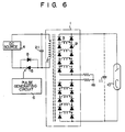
- the transformer 1 comprises a primary winding 2 and a plurality of independent secondary windings 3 and is rendered coreless (namely, has an air core).
- a D.C. source 4 is formed of a rectifying power source for rectifying and smoothing, for example, a commercial power source. Connected between a pair of output terminals of said D.C. source 4 is a series circuit consisting of the primary winding 2 of the transformer 1 and GTO thyristor 5 acting as a switching element. The gate of the GTO thyristor 5 is supplied with an output control pulse from a control pulse generator 6.
- each secondary winding has a polarity opposite to that of the adjacent secondary winding, as indicated by a dot ".” attached to the respective secondary windings.
- the rectifier diodes collectively constitute a rectification circuit which eventually adds up all the output currents from the plural secondary windings in the direction of the same polarity and performs full-wave rectification.
- An X-ray tube 10 is connected to said rectification circuit as a high voltage and high power load.
- the capacitor 11 shown in Fig. 1 represents a stray capacitive component remaining in a cable through which power is supplied from the transformer 1 to the X-ray tube 10, and acts as a smoothing capacitor for high frequency power.
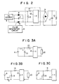
- the coreless transformer 1 is equivalently constituted by an ideal transformer 12, exciting inductance 13, and leakage inductance 14 prevailing between the primary winding 2 and secondary winding 3.
- the GTO thyristor 5 fails to retain a state of saturated conduction, unless a gate current always runs through said GTO thyristor 5, and indicates a slight time lag (a storage period Ts) between the point of time at which a reverse bias nonconducting pulse is issued and the point of time at which the GTO thyristor 5 is rendered nonconductive.
- the leakage inductance 14 is defined to mean an inductance as viewed from the primary side of the transformer 1 when the secondary winding 3 thereof is short-circuited.
- the equivalent circuit shows the arrangement of Fig. 3B.
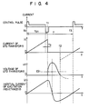
- the circuit of a high voltage generator embodying this invention is designed in such a manner that, as shown in Fig. 4, the inertial current il delineates a waveform representing its running course by which said inertial current il first falls to the negative side as mentioned above, and then regains a zero level at the termination of a switching period T, namely, in the proximity of the starting point of the succeeding switching period (when the switching element 5 is rendered conductive a second time).
- the high voltage generator of this invention not only involves said advised consideration but also carries out a self- stabilizing function. Therefore, same displacement of timing, from the point of time at which the inertial current il regains a zero level, is automatically corrected by the circuit itself, which therefore tends to be stabilized, as shown in Fig. 4.
- the magnitude of said power is defined by the power Pin correspnding to a current supplied during the period Ton (t0 to t1), that is, the power supplied from the power source 4, and a return power Pret indicated by a current brought back to the power source 4. Therefore, the net power Pout supplied from the power source 4 to the load 10 is expressed as follows:
- the application of a coreless transformer generally tends to be accompanied with the drawback that a magnetic connection between the primary and secondary windings tends to be more weakened than when a core transformer is used.
- the coreless transformer 1 of the subject high voltage generator is constructed by dividing the secondary winding into sections 3.
- the sections of the secondary winding 3 of the coreless transformer 1 are wound about the outer periphery and/or the inner periphery of the primary winding 2.
- a good electromagnetic bonding is realized between both primary and secondary windings 2, 3. Since the transformer is operated with a high frequency, which is adapted to provide a strong electromagnetic bonding, even the application of the coreless transformer 1 gives rise to substantially no decline in the electromagnetic bonding.
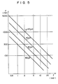
- a test was made of the high voltage generators embodying this invention, which respectively involved said four samples of the coreless transformer 1. Determination was made of the relationship between the operation frquency f and the quantity Pout of a supplied power which was observed under the condition of:
- the high voltage generator of this invention which involves the aforementioned coreless transformer, can attain the above-mentioned object.
- the switch element of the subject high voltage generator can be provided not only by the aforementioned GTO thyristor 5, but also by the so-called giant transistor, thyristor or any other electronic switch element having the same control function as the aforementioned elements.
- an electronic switch element for example, a thyristor having no self-extinguishing function, is applied, it is of course necessary to provide an extinguishing circuit interlockingly operative with the control pulse generator 6 forthe purpose of effecting extinction.
Landscapes
- Engineering & Computer Science (AREA)
- Power Engineering (AREA)
- Dc-Dc Converters (AREA)
- X-Ray Techniques (AREA)
- Rectifiers (AREA)
Claims (8)
Applications Claiming Priority (2)
| Application Number | Priority Date | Filing Date | Title |
|---|---|---|---|
| JP58177376A JPS6070968A (ja) | 1983-09-26 | 1983-09-26 | 高圧発生装置 |
| JP177376/83 | 1983-09-26 |
Publications (3)
| Publication Number | Publication Date |
|---|---|
| EP0141985A1 EP0141985A1 (de) | 1985-05-22 |
| EP0141985B1 true EP0141985B1 (de) | 1987-12-09 |
| EP0141985B2 EP0141985B2 (de) | 1992-08-05 |
Family
ID=16029858
Family Applications (1)
| Application Number | Title | Priority Date | Filing Date |
|---|---|---|---|
| EP84111492A Expired EP0141985B2 (de) | 1983-09-26 | 1984-09-26 | Hochspannungsgenerator |
Country Status (4)
| Country | Link |
|---|---|
| US (1) | US4725938A (de) |
| EP (1) | EP0141985B2 (de) |
| JP (1) | JPS6070968A (de) |
| DE (1) | DE3468080D1 (de) |
Cited By (3)
| Publication number | Priority date | Publication date | Assignee | Title |
|---|---|---|---|---|
| EP0307057A1 (de) * | 1987-09-07 | 1989-03-15 | Alcatel Nederland B.V. | Energiekonverter |
| EP0556134A3 (de) * | 1992-02-14 | 1993-10-06 | Cableco | Schaltungsanordnung zur Stromregelung in einer Last |
| EP0684688A1 (de) | 1994-05-27 | 1995-11-29 | Philips Patentverwaltung GmbH | Leistungsgenerator mit einem Transformator |
Families Citing this family (17)
| Publication number | Priority date | Publication date | Assignee | Title |
|---|---|---|---|---|
| JPS6081813A (ja) * | 1983-10-12 | 1985-05-09 | Toshiba Corp | 高圧トランス |
| WO1993023914A1 (en) * | 1992-05-11 | 1993-11-25 | Electric Power Research Institute | Harmonic blocking converter system |
| WO1993023913A1 (en) * | 1992-05-11 | 1993-11-25 | Electric Power Research Institute | Optimized high power voltage sourced inverter system |
| US5519312A (en) * | 1993-11-29 | 1996-05-21 | Alfred University | Hybrid system of fuel cell and superconducting magnetic energy storage device |
| US7768371B2 (en) | 1998-02-05 | 2010-08-03 | City University Of Hong Kong | Coreless printed-circuit-board (PCB) transformers and operating techniques therefor |
| JP3983982B2 (ja) | 1999-05-25 | 2007-09-26 | ジェンデックス・コーポレーション | 歯科用x線装置 |
| DE10010278A1 (de) * | 2000-03-02 | 2001-09-06 | Peter Mandl | Schaltungsanordnung für Gleichrichter mit veränderbaren Ausgangsparametern |
| US6765987B2 (en) * | 2001-03-15 | 2004-07-20 | Safe Food Technologies, Inc. | Resonant plasma x-ray source |
| DE102004001478B4 (de) * | 2004-01-09 | 2015-09-24 | Semikron Elektronik Gmbh & Co. Kg | Stromrichterschaltungsanordnung zur Umformung einer Wechselspannung in eine Hochvoltgleichspannung |
| EP1860838B1 (de) * | 2006-05-24 | 2013-08-14 | Infineon Technologies AG | Datenübertragung durch Phasenmodulation über zwei Signalpfaden |
| DE102007032808A1 (de) * | 2007-07-13 | 2009-01-15 | Siemens Ag | Potenzialsteuerung bei Hochspannungsvorrichtungen |
| CN101635514B (zh) | 2009-08-27 | 2012-05-23 | 北京交通大学 | 采用多分裂变压器的高压电源电路 |
| US9800133B2 (en) * | 2016-03-22 | 2017-10-24 | Infineon Technologies Ag | Active common mode cancellation |
| US10916369B2 (en) | 2016-11-08 | 2021-02-09 | Koninklijke Philips N.V. | Inductor for high frequency and high power applications |
| US11103207B1 (en) * | 2017-12-28 | 2021-08-31 | Radiation Monitorng Devices, Inc. | Double-pulsed X-ray source and applications |
| US11901153B2 (en) * | 2021-03-05 | 2024-02-13 | Pct Ebeam And Integration, Llc | X-ray machine |
| US12282045B2 (en) | 2022-12-02 | 2025-04-22 | Infineon Technologies Ag | Common mode evaluation in a differential galvanic isolation signal transmission circuit |
Family Cites Families (11)
| Publication number | Priority date | Publication date | Assignee | Title |
|---|---|---|---|---|
| US3197691A (en) * | 1962-01-02 | 1965-07-27 | Gen Electric | Regulated power supply |
| US3419786A (en) * | 1966-12-27 | 1968-12-31 | Westinghouse Electric Corp | Electrical converter apparatus for rectifying and adding a plurality of a.c. voltages |
| DE2750544A1 (de) | 1977-11-11 | 1979-05-17 | Siemens Ag | Roentgendiagnostikgenerator mit einem seinen hochspannungstransformator speisenden wechselrichter |
| GB2050081B (en) * | 1979-03-15 | 1982-12-08 | Tokyo Shibaura Electric Co | High frequency switching regulator circuit |
| JPS56150968A (en) * | 1980-04-22 | 1981-11-21 | Toshiba Corp | Switching circuit of single end high frequency |
| US4339704A (en) * | 1980-07-07 | 1982-07-13 | General Electric Company | Series parallel transition for power supply |
| US4386395A (en) * | 1980-12-19 | 1983-05-31 | Webster Electric Company, Inc. | Power supply for electrostatic apparatus |
| JPS57138866A (en) * | 1981-02-17 | 1982-08-27 | Toshiba Corp | Voltage resonance type high frequency switching circuit |
| US4366532A (en) * | 1981-05-11 | 1982-12-28 | Westinghouse Electric Corp. | AC/DC or DC/AC Converter system with improved AC-line harmonic reduction |
| JPS5947976A (ja) * | 1982-09-08 | 1984-03-17 | Toshiba Corp | 高圧発生回路 |
| US4480298A (en) * | 1983-01-25 | 1984-10-30 | Westinghouse Electric Corp. | Multiple output DC-to-DC voltage converter apparatus |
-
1983
- 1983-09-26 JP JP58177376A patent/JPS6070968A/ja active Granted
-
1984
- 1984-09-26 EP EP84111492A patent/EP0141985B2/de not_active Expired
- 1984-09-26 DE DE8484111492T patent/DE3468080D1/de not_active Expired
-
1986
- 1986-09-29 US US06/912,657 patent/US4725938A/en not_active Expired - Lifetime
Cited By (4)
| Publication number | Priority date | Publication date | Assignee | Title |
|---|---|---|---|---|
| EP0307057A1 (de) * | 1987-09-07 | 1989-03-15 | Alcatel Nederland B.V. | Energiekonverter |
| EP0556134A3 (de) * | 1992-02-14 | 1993-10-06 | Cableco | Schaltungsanordnung zur Stromregelung in einer Last |
| EP0684688A1 (de) | 1994-05-27 | 1995-11-29 | Philips Patentverwaltung GmbH | Leistungsgenerator mit einem Transformator |
| US5586017A (en) * | 1994-05-27 | 1996-12-17 | U.S. Philips Corporation | Power generator comprising a transformer |
Also Published As
| Publication number | Publication date |
|---|---|
| JPS6070968A (ja) | 1985-04-22 |
| EP0141985B2 (de) | 1992-08-05 |
| EP0141985A1 (de) | 1985-05-22 |
| JPH0515151B2 (de) | 1993-02-26 |
| DE3468080D1 (en) | 1988-01-21 |
| US4725938A (en) | 1988-02-16 |
Similar Documents
| Publication | Publication Date | Title |
|---|---|---|
| EP0141985B1 (de) | Hochspannungsgenerator | |
| US4914561A (en) | Dual transformer device for power converters | |
| AU612118B2 (en) | High voltage power supply particularly adapted for a TWT | |
| US4525774A (en) | Regulated AC-DC converter having saturation inductance in resonant circuit | |
| EP0610158B1 (de) | Im Nulldurchgang schaltender Schaltwandler fester Frequenz | |
| US5459650A (en) | Power supply circuit | |
| US5438497A (en) | Tertiary side resonant DC/DC converter | |
| EP0291120B1 (de) | Gesteuerte Hochfrequenzleistungsversorgung | |
| WO1991000643A1 (en) | Ac/dc conversion with reduced supply waveform distortion | |
| US5563775A (en) | Full bridge phase displaced resonant transition circuit for obtaining constant resonant transition current from 0° phase angle to 180° phase angle | |
| US4417153A (en) | High frequency switching circuit | |
| US4445166A (en) | High voltage converter | |
| US5317496A (en) | DC/DC-converter with a primary circuit and at least one secondary circuit tuned as individually oscillatory circuits | |
| US4276587A (en) | DC to DC Converter | |
| US6282103B1 (en) | Switching power supply using an inductor device to prevent harmonic current generation | |
| DE19824409A1 (de) | AC-DC-Wandler | |
| US4530043A (en) | DC switching voltage converter for multiplying an input DC voltage without increasing the switching conduction period | |
| US5317494A (en) | Power supply circuit utilizing voltage and current resonance for reducing switching loss | |
| US4435747A (en) | High voltage supply system for medical equipment | |
| US4401902A (en) | High frequency switching circuit | |
| US5327334A (en) | Zero current switching DC-DC converter incorporating a tapped resonant inductor | |
| JPH0974741A (ja) | コンバータ | |
| EP0146225A1 (de) | Wechselrichter für einen Röntgenstrahlerzeuger | |
| US4660134A (en) | DC-DC converter with chopping switch and transformer | |
| EP0534379A2 (de) | Leistungsversorgungsschaltung |
Legal Events
| Date | Code | Title | Description |
|---|---|---|---|
| PUAI | Public reference made under article 153(3) epc to a published international application that has entered the european phase |
Free format text: ORIGINAL CODE: 0009012 |
|
| 17P | Request for examination filed |
Effective date: 19840926 |
|
| AK | Designated contracting states |
Designated state(s): DE FR GB NL |
|
| 17Q | First examination report despatched |
Effective date: 19860425 |
|
| GRAA | (expected) grant |
Free format text: ORIGINAL CODE: 0009210 |
|
| AK | Designated contracting states |
Kind code of ref document: B1 Designated state(s): DE FR NL |
|
| REF | Corresponds to: |
Ref document number: 3468080 Country of ref document: DE Date of ref document: 19880121 |
|
| ET | Fr: translation filed | ||
| PLBI | Opposition filed |
Free format text: ORIGINAL CODE: 0009260 |
|
| 26 | Opposition filed |
Opponent name: SIEMENS AKTIENGESELLSCHAFT, BERLIN UND MUENCHEN Effective date: 19880425 |
|
| NLR1 | Nl: opposition has been filed with the epo |
Opponent name: SIEMENS AKTIENGESELLSCHAFT |
|
| PUAH | Patent maintained in amended form |
Free format text: ORIGINAL CODE: 0009272 |
|
| STAA | Information on the status of an ep patent application or granted ep patent |
Free format text: STATUS: PATENT MAINTAINED AS AMENDED |
|
| 27A | Patent maintained in amended form |
Effective date: 19920805 |
|
| AK | Designated contracting states |
Kind code of ref document: B2 Designated state(s): DE FR NL |
|
| NLR2 | Nl: decision of opposition | ||
| NLR3 | Nl: receipt of modified translations in the netherlands language after an opposition procedure | ||
| ET3 | Fr: translation filed ** decision concerning opposition | ||
| PGFP | Annual fee paid to national office [announced via postgrant information from national office to epo] |
Ref country code: FR Payment date: 19990909 Year of fee payment: 16 |
|
| PGFP | Annual fee paid to national office [announced via postgrant information from national office to epo] |
Ref country code: DE Payment date: 19990927 Year of fee payment: 16 |
|
| PGFP | Annual fee paid to national office [announced via postgrant information from national office to epo] |
Ref country code: NL Payment date: 19990930 Year of fee payment: 16 |
|
| PG25 | Lapsed in a contracting state [announced via postgrant information from national office to epo] |
Ref country code: NL Free format text: LAPSE BECAUSE OF NON-PAYMENT OF DUE FEES Effective date: 20010401 |
|
| PG25 | Lapsed in a contracting state [announced via postgrant information from national office to epo] |
Ref country code: FR Free format text: LAPSE BECAUSE OF NON-PAYMENT OF DUE FEES Effective date: 20010531 |
|
| NLV4 | Nl: lapsed or anulled due to non-payment of the annual fee |
Effective date: 20010401 |
|
| PG25 | Lapsed in a contracting state [announced via postgrant information from national office to epo] |
Ref country code: DE Free format text: LAPSE BECAUSE OF NON-PAYMENT OF DUE FEES Effective date: 20010601 |
|
| REG | Reference to a national code |
Ref country code: FR Ref legal event code: ST |
|
| APAH | Appeal reference modified |
Free format text: ORIGINAL CODE: EPIDOSCREFNO |