EP0141871A2 - Förderer zum Transportieren einer Reihe von Gegenständen - Google Patents
Förderer zum Transportieren einer Reihe von Gegenständen Download PDFInfo
- Publication number
- EP0141871A2 EP0141871A2 EP83111367A EP83111367A EP0141871A2 EP 0141871 A2 EP0141871 A2 EP 0141871A2 EP 83111367 A EP83111367 A EP 83111367A EP 83111367 A EP83111367 A EP 83111367A EP 0141871 A2 EP0141871 A2 EP 0141871A2
- Authority
- EP
- European Patent Office
- Prior art keywords
- conveyor
- articles
- delaying means
- feeding members
- discharging
- Prior art date
- Legal status (The legal status is an assumption and is not a legal conclusion. Google has not performed a legal analysis and makes no representation as to the accuracy of the status listed.)
- Granted
Links
- 238000007599 discharging Methods 0.000 claims abstract description 9
- 230000002093 peripheral effect Effects 0.000 claims description 6
- 238000011144 upstream manufacturing Methods 0.000 claims description 3
- 230000003111 delayed effect Effects 0.000 description 4
- 230000001133 acceleration Effects 0.000 description 2
- 238000004806 packaging method and process Methods 0.000 description 2
- 230000000063 preceeding effect Effects 0.000 description 1
Images


Classifications
-
- B—PERFORMING OPERATIONS; TRANSPORTING
- B65—CONVEYING; PACKING; STORING; HANDLING THIN OR FILAMENTARY MATERIAL
- B65G—TRANSPORT OR STORAGE DEVICES, e.g. CONVEYORS FOR LOADING OR TIPPING, SHOP CONVEYOR SYSTEMS OR PNEUMATIC TUBE CONVEYORS
- B65G47/00—Article or material-handling devices associated with conveyors; Methods employing such devices
- B65G47/22—Devices influencing the relative position or the attitude of articles during transit by conveyors
- B65G47/26—Devices influencing the relative position or the attitude of articles during transit by conveyors arranging the articles, e.g. varying spacing between individual articles
- B65G47/30—Devices influencing the relative position or the attitude of articles during transit by conveyors arranging the articles, e.g. varying spacing between individual articles during transit by a series of conveyors
- B65G47/31—Devices influencing the relative position or the attitude of articles during transit by conveyors arranging the articles, e.g. varying spacing between individual articles during transit by a series of conveyors by varying the relative speeds of the conveyors forming the series
Definitions
- the distances between successive articles travelling on a conveyor of such kind may be variable, depending on the manner of loading the articles onto a conveyor. In many cases, however, it may be desirable that the articles arriving at the discharge or treatment zone have uniform distances between themselves.
- An example of such a case is where the discharge zone is provided with an abutment wall and a reciprocatable pusher for pushing, with each stroke, a predetermined number of articles r which have been stopped by said abutment wall, transversely from the conveyor onto a receiving surface such as a table, another conveyor etc. If the articles arrive w-ith..varying distances, i.e. at random,at such a discharging station, serious problems may arise.
- the pusher may during its forward or return stroke interfere with an arriving article. If the distance between two successive articles is too great, an article which is supposed to be transferred by the pusher might fail to become properly engaged by the pusher and may therefore be moved into a faulty position.
- this object is achieved by delaying means located a distance upstream of said discharging or treatment zone and comprising two feeding members arranged substantially upright at either side of the conveyor for engaging the side faces of the articles passing between them on the conveyor, said feeding members being driven for peripheral movement in the same direction as the conveyor and with a peripheral speed lower than the speed of the conveyor.
- An article becoming engaged by the delaying means will be delayed with respect to the travelling speed of the conveyor. If this delay is sufficiently large for a subsequent article to .abut against the article being delayed, the two articles will pass through the delaying means in contact with each other. In other words, any gap which might have existed between the two articles ahead of the delaying means, and which might have been of variable length, has been closed. As the article has passed through the delaying means and is released therefrom, it will again be accelerated by the conveyor up to the travelling speed of the latter, thereby creating again a gap between this article and the following one which is still being held in the delaying means.
- This new gap depends only on the ratio of the velocities of the conveyor and the delaying means and is therefore independent on the length of the gap which has existed ahead of the delaying means. Accordingly, the articles will all leave the delaying means with uniform distances between themselves.
- the ratio between the velocity V2 of the delaying means and the velocity V1 of the conveyor must fulfil the condition where d max is the maximum distance occurring between two successive articles, and 1 is the length of each article.
- d max is the maximum distance occurring between two successive articles
- 1 is the length of each article.
- the distance between the articles cannot only be equalized, but can also be set to a desired predetermined value by suitably choosing the ratio of velocities of the delaying means and the conveyor.
- each feeding member in the delaying means is a substantially vertical endless belt.
- the belts are set at a distance substantially equal to or slightly smaller than the width of the articles travelling on the conveyor.
- the flexibility of the belts may be sufficient to resiliently grip the articles passing therebetween.
- the guiding rollers around which the belts travel may be mounted for being resiliently biased against the articles.
- additional feeding members are arranged between the delaying means and the discharging or treatment zone, these additional feeding members, for example substantially vertical belts, being driven at substantially the same speed as the conveyor, for accelerating the articles leaving the delaying means.
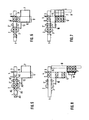
- Each said further conveyor 5 is provided with a further abutment wall or stopper 5' and a further pusher 6 for transferring a predetermined number of articles, which have been accumulated by repeated strokes of the pusher 4, onto a further receiving surface, .such as a pallet or tray 7, located adjacent the conveyor 5. Thereafter the palette or tray 7 may travel on a rail 8 to a position in front of a further pusher 9, which transfers the number of articles accumulated on the palette or tray 7 onto a final receiving surface, such as a packaging container, transport pallet or the like.
- each conveyor 1 On both sides of each conveyor 1, which travels at a constant, predetermined speed, vertical belts 2 are provided.
- Each vertical belt 2 may be a single belt or a plurality of narrow belts arranged vertically above and spaced from each other.
- the belts travel around guide and support rollers which may be mounted resilie.ntly biased towards the conveyor 1.
- the vertical belts 2 are driven to travel at a predetermined constant speed which is lower than the travelling speed of the conveyor 1.
- the articles are again accelerated up to the travelling speed of the conveyor 1.
- This acceleration may be assisted by an additional set of vertical belts 2', which is arranged between the set of delaying belts 2 and the pusher 4.
- These additional belts 2' are driven with the same speed as the conveyor 1, and by engaging between themselves the articledemerging from the delaying belts 2, they will effectively and quickly accelerate the articles up to the driving speed of the conveyor 1, even if the articles had been delayed to a rather low velocity, or almost to a stop, by the delaying belts 2.
- the articles when leaving the delaying belts 2, by virtue of their acceleration are separated again from each other and form a uniform constant distance d between successive articles such as A1, A2, A3 in fig. 2. Accordingly, the articles arrive at a uniform flow rate, i.e. in regular time intervals in the range of the pusher 4.
- the articles are conveyed by the conveyor 1 to the stopper 3, they are stopped by the stopper 3 and a predetermined number of articles, for example two articles A1, A2 in the embodiment shown, is accumulated in front of the stopper 3.
- the pusher 4 provided at the side of the stopper 3 commenses to be actuated in the arrow direction of fig. 3 and pushes out the articles A1, A2 onto the adjacent receiving surface or conveyor 5 (see fig. 4).
- the pusher is provided, on the side facing the upstream direction of the conveyor 1, with an impeding plate 4a, by which the following article arriving on the conveyor 2 may be intercepted during the return stroke of the pusher 4.
- the pusher 4 As soon as the pusher 4 has reached its return position, the following article continues to travel with the conveyor 1 for reaching the location in abutment with the stopper 3. Thereafter, as soon as the article A4 following A3 is in contact with A3, the pusher 4 is again actuated, pushing out both articles A3 and A4 onto the conveyor 5 (see fig. 6).
- the articles Owing to the uniformity of the distance d of the articles the articles will not inadvertently interfere with the pusher 4 during, its forward or return stroke, and even during the return stroke of the pusher 4 at maximum one article may engage against the impeding wall 4a, and therefore the lateral force exerted on the pusher by that article due to its friction against the conveyor 1 will only be low.
- the vertical belts 2 are driven for constant travelling movement, without intermittent stops.
- Repetition of the aforementioned steps results in accumulating a plurality of pairs of articles A1, A2, etc., on the receiving conveyor 5. These pairs of articles become eventually stopped by engagement with the stopper 5'. At this time a prescribed number of articles (for example six articles in fig. 7) have been accumulated on the conveyor 5 in front of the stopper 5', and this group of articles is then transferred in one operation by the further pusher 6 onto the tray or pallet 7 located adjacent the conveyor 5.
- each group of six articles is successively pushed onto a further receiving surface (not shown), whereby a desired number of articles (in groups of six articles) can be accumulated at the receiving surface in front of the pusher 9, which may for example be a packaging container or transporting palette.
- vertical belts 2 have been shown as feeding members in the delaying means, other feeding members, such as rolls or sets of rolls, driven at a peripheral speed equal to that of the conveyor 1, may be used. However,' the use of vertical belts 2 provides the additional advantage that the successive articles will also be effectively aligned in the longitudinal direction of the conveyor 1.
Landscapes
- Engineering & Computer Science (AREA)
- Mechanical Engineering (AREA)
- Attitude Control For Articles On Conveyors (AREA)
- Intermediate Stations On Conveyors (AREA)
- Vending Machines For Individual Products (AREA)
- Electrical Discharge Machining, Electrochemical Machining, And Combined Machining (AREA)
- Chain Conveyers (AREA)
- Special Conveying (AREA)
- Structure Of Belt Conveyors (AREA)
Priority Applications (6)
| Application Number | Priority Date | Filing Date | Title |
|---|---|---|---|
| CA000439574A CA1215341A (en) | 1983-11-14 | 1983-10-24 | Article conveyance device |
| AT83111367T ATE44709T1 (de) | 1983-11-14 | 1983-11-14 | Foerderer zum transportieren einer reihe von gegenstaenden. |
| DE198383111367T DE141871T1 (de) | 1983-11-14 | 1983-11-14 | Foerderer zum transportieren einer reihe von gegenstaenden. |
| EP83111367A EP0141871B1 (de) | 1983-11-14 | 1983-11-14 | Förderer zum Transportieren einer Reihe von Gegenständen |
| DE8383111367T DE3380211D1 (en) | 1983-11-14 | 1983-11-14 | A conveyor for conveying a succession of articles |
| AU21593/83A AU566904B2 (en) | 1983-11-14 | 1983-11-22 | Article conveyance device |
Applications Claiming Priority (1)
| Application Number | Priority Date | Filing Date | Title |
|---|---|---|---|
| EP83111367A EP0141871B1 (de) | 1983-11-14 | 1983-11-14 | Förderer zum Transportieren einer Reihe von Gegenständen |
Publications (3)
| Publication Number | Publication Date |
|---|---|
| EP0141871A2 true EP0141871A2 (de) | 1985-05-22 |
| EP0141871A3 EP0141871A3 (en) | 1986-08-27 |
| EP0141871B1 EP0141871B1 (de) | 1989-07-19 |
Family
ID=8190803
Family Applications (1)
| Application Number | Title | Priority Date | Filing Date |
|---|---|---|---|
| EP83111367A Expired EP0141871B1 (de) | 1983-11-14 | 1983-11-14 | Förderer zum Transportieren einer Reihe von Gegenständen |
Country Status (5)
| Country | Link |
|---|---|
| EP (1) | EP0141871B1 (de) |
| AT (1) | ATE44709T1 (de) |
| AU (1) | AU566904B2 (de) |
| CA (1) | CA1215341A (de) |
| DE (2) | DE3380211D1 (de) |
Cited By (2)
| Publication number | Priority date | Publication date | Assignee | Title |
|---|---|---|---|---|
| CN111674626A (zh) * | 2020-07-09 | 2020-09-18 | 健民集团叶开泰国药(随州)有限公司 | 一种药品连续装盒装置 |
| CN114355844A (zh) * | 2020-10-13 | 2022-04-15 | 顺丰科技有限公司 | 物品靠边分离方法、装置以及系统 |
Families Citing this family (1)
| Publication number | Priority date | Publication date | Assignee | Title |
|---|---|---|---|---|
| CN102351101A (zh) * | 2011-10-10 | 2012-02-15 | 越峰电子(广州)有限公司 | 软磁铁氧体成型后的生胚自动排列机 |
Family Cites Families (6)
| Publication number | Priority date | Publication date | Assignee | Title |
|---|---|---|---|---|
| GB894825A (en) * | 1958-05-05 | 1962-04-26 | Toronto Star Ltd | Improvements in or relating to conveyor assemblies |
| GB1119122A (en) * | 1964-10-05 | 1968-07-10 | Remy & Cie E P | Device for spacing objects on a conveyor |
| GB1471769A (en) * | 1974-04-10 | 1977-04-27 | Metal Box Co Ltd | Regulating the movement of articles along a path |
| GB1551723A (en) * | 1975-08-16 | 1979-08-30 | Molins Ltd | Conveyors for rod/like articles |
| FR2350285A1 (fr) * | 1976-05-04 | 1977-12-02 | Tourres Francois | Installations de manutention en continu de conteneurs, tels que notamment des bouteilles de verre |
| SE417939B (sv) * | 1978-05-05 | 1981-04-27 | Arenco Match Machinery Ab | Sett for astadkommande av reorientering av foremal i en foljd av pa varandra foljande foremal samt anordning for genomforande av settet |
-
1983
- 1983-10-24 CA CA000439574A patent/CA1215341A/en not_active Expired
- 1983-11-14 EP EP83111367A patent/EP0141871B1/de not_active Expired
- 1983-11-14 AT AT83111367T patent/ATE44709T1/de not_active IP Right Cessation
- 1983-11-14 DE DE8383111367T patent/DE3380211D1/de not_active Expired
- 1983-11-14 DE DE198383111367T patent/DE141871T1/de active Pending
- 1983-11-22 AU AU21593/83A patent/AU566904B2/en not_active Ceased
Cited By (2)
| Publication number | Priority date | Publication date | Assignee | Title |
|---|---|---|---|---|
| CN111674626A (zh) * | 2020-07-09 | 2020-09-18 | 健民集团叶开泰国药(随州)有限公司 | 一种药品连续装盒装置 |
| CN114355844A (zh) * | 2020-10-13 | 2022-04-15 | 顺丰科技有限公司 | 物品靠边分离方法、装置以及系统 |
Also Published As
| Publication number | Publication date |
|---|---|
| DE3380211D1 (en) | 1989-08-24 |
| AU2159383A (en) | 1985-05-30 |
| DE141871T1 (de) | 1986-04-10 |
| ATE44709T1 (de) | 1989-08-15 |
| CA1215341A (en) | 1986-12-16 |
| AU566904B2 (en) | 1987-11-05 |
| EP0141871B1 (de) | 1989-07-19 |
| EP0141871A3 (en) | 1986-08-27 |
Similar Documents
| Publication | Publication Date | Title |
|---|---|---|
| EP0139775B1 (de) | Stau- und Transportvorrichtung für Gegenstände | |
| US6182814B1 (en) | Inline vacuum slug feeder | |
| NL1003035C2 (nl) | Dragerinrichting voor het dragen van een aantal produkten, alsmede systeem voorzien van een dergelijke dragerinrichting. | |
| US20150158611A1 (en) | Variable pitch packaging apparatus and methods | |
| EP0588298B1 (de) | Vorrichtung zur Gruppierung von Gegenständen | |
| EP1764318A1 (de) | Zurückziehbare Übergabeeinrichtung für eine Dosiervorrichtung | |
| US3835985A (en) | Vacuum assist can unscrambler | |
| KR910007775A (ko) | 물품 이송장치 | |
| US4359214A (en) | Apparatus for feeding flat articles | |
| US10926961B2 (en) | Multiline transfer of product | |
| US3373860A (en) | Conveyor system | |
| WO2012064277A1 (en) | Transition device | |
| CN106660711B (zh) | 用于输送块式产品的方法和装置 | |
| WO2017151051A1 (en) | Transfer device, conveyor system comprising a transfer device, method for grouping objects by using a transfer device | |
| US7249672B2 (en) | Device for continuously delivering bags | |
| CA1287319C (en) | Load spacing conveyor system | |
| EP0141871A2 (de) | Förderer zum Transportieren einer Reihe von Gegenständen | |
| EP0315807B1 (de) | Verfahren und Vorrichtung für das Stapeln von Artikeln und das Zuführen der Stapel an einen Abfuhrbereich | |
| EP1634827B1 (de) | Verfahren und Vorrichtung zum Überbringen von Produkten | |
| JPS62285817A (ja) | 物品区分け装置 | |
| US3859898A (en) | Method of and apparatus for stacking flexible articles | |
| JP2007508218A (ja) | スタッカー | |
| US3677391A (en) | Apparatus and method for shingling articles of uniform non-planar shape | |
| US4526266A (en) | Dual-T transfer conveyor | |
| US4354591A (en) | Carton collating and transfer apparatus |
Legal Events
| Date | Code | Title | Description |
|---|---|---|---|
| PUAI | Public reference made under article 153(3) epc to a published international application that has entered the european phase |
Free format text: ORIGINAL CODE: 0009012 |
|
| AK | Designated contracting states |
Designated state(s): AT BE CH DE FR GB IT LI NL SE |
|
| ITCL | It: translation for ep claims filed |
Representative=s name: SOCIETA' ITALIANA BREVETTI S.P.A. |
|
| EL | Fr: translation of claims filed | ||
| TCNL | Nl: translation of patent claims filed | ||
| TCAT | At: translation of patent claims filed | ||
| DET | De: translation of patent claims | ||
| PUAL | Search report despatched |
Free format text: ORIGINAL CODE: 0009013 |
|
| RHK1 | Main classification (correction) |
Ipc: B65G 47/31 |
|
| AK | Designated contracting states |
Kind code of ref document: A3 Designated state(s): AT BE CH DE FR GB IT LI NL SE |
|
| 17P | Request for examination filed |
Effective date: 19861105 |
|
| RAP1 | Party data changed (applicant data changed or rights of an application transferred) |
Owner name: AB TETRA PAK |
|
| 17Q | First examination report despatched |
Effective date: 19870817 |
|
| GRAA | (expected) grant |
Free format text: ORIGINAL CODE: 0009210 |
|
| AK | Designated contracting states |
Kind code of ref document: B1 Designated state(s): AT BE CH DE FR GB IT LI NL SE |
|
| REF | Corresponds to: |
Ref document number: 44709 Country of ref document: AT Date of ref document: 19890815 Kind code of ref document: T |
|
| REF | Corresponds to: |
Ref document number: 3380211 Country of ref document: DE Date of ref document: 19890824 |
|
| ITF | It: translation for a ep patent filed | ||
| RAP2 | Party data changed (patent owner data changed or rights of a patent transferred) |
Owner name: AB TETRA PAK |
|
| ET | Fr: translation filed | ||
| PLBE | No opposition filed within time limit |
Free format text: ORIGINAL CODE: 0009261 |
|
| STAA | Information on the status of an ep patent application or granted ep patent |
Free format text: STATUS: NO OPPOSITION FILED WITHIN TIME LIMIT |
|
| 26N | No opposition filed | ||
| ITTA | It: last paid annual fee | ||
| EAL | Se: european patent in force in sweden |
Ref document number: 83111367.5 |
|
| PGFP | Annual fee paid to national office [announced via postgrant information from national office to epo] |
Ref country code: FR Payment date: 19971021 Year of fee payment: 15 |
|
| PGFP | Annual fee paid to national office [announced via postgrant information from national office to epo] |
Ref country code: SE Payment date: 19971022 Year of fee payment: 15 |
|
| PGFP | Annual fee paid to national office [announced via postgrant information from national office to epo] |
Ref country code: AT Payment date: 19971024 Year of fee payment: 15 |
|
| PGFP | Annual fee paid to national office [announced via postgrant information from national office to epo] |
Ref country code: GB Payment date: 19971027 Year of fee payment: 15 |
|
| PGFP | Annual fee paid to national office [announced via postgrant information from national office to epo] |
Ref country code: DE Payment date: 19971029 Year of fee payment: 15 Ref country code: CH Payment date: 19971029 Year of fee payment: 15 |
|
| PGFP | Annual fee paid to national office [announced via postgrant information from national office to epo] |
Ref country code: NL Payment date: 19971031 Year of fee payment: 15 |
|
| PGFP | Annual fee paid to national office [announced via postgrant information from national office to epo] |
Ref country code: BE Payment date: 19971118 Year of fee payment: 15 |
|
| PG25 | Lapsed in a contracting state [announced via postgrant information from national office to epo] |
Ref country code: GB Free format text: LAPSE BECAUSE OF NON-PAYMENT OF DUE FEES Effective date: 19981114 Ref country code: AT Free format text: LAPSE BECAUSE OF NON-PAYMENT OF DUE FEES Effective date: 19981114 |
|
| PG25 | Lapsed in a contracting state [announced via postgrant information from national office to epo] |
Ref country code: SE Free format text: LAPSE BECAUSE OF NON-PAYMENT OF DUE FEES Effective date: 19981115 |
|
| PG25 | Lapsed in a contracting state [announced via postgrant information from national office to epo] |
Ref country code: LI Free format text: LAPSE BECAUSE OF NON-PAYMENT OF DUE FEES Effective date: 19981130 Ref country code: CH Free format text: LAPSE BECAUSE OF NON-PAYMENT OF DUE FEES Effective date: 19981130 Ref country code: BE Free format text: LAPSE BECAUSE OF NON-PAYMENT OF DUE FEES Effective date: 19981130 |
|
| BERE | Be: lapsed |
Owner name: TETRA PAK A.B. Effective date: 19981130 |
|
| PG25 | Lapsed in a contracting state [announced via postgrant information from national office to epo] |
Ref country code: NL Free format text: LAPSE BECAUSE OF NON-PAYMENT OF DUE FEES Effective date: 19990601 |
|
| GBPC | Gb: european patent ceased through non-payment of renewal fee |
Effective date: 19981114 |
|
| REG | Reference to a national code |
Ref country code: CH Ref legal event code: PL |
|
| PG25 | Lapsed in a contracting state [announced via postgrant information from national office to epo] |
Ref country code: FR Free format text: LAPSE BECAUSE OF NON-PAYMENT OF DUE FEES Effective date: 19990730 |
|
| EUG | Se: european patent has lapsed |
Ref document number: 83111367.5 |
|
| NLV4 | Nl: lapsed or anulled due to non-payment of the annual fee |
Effective date: 19990601 |
|
| REG | Reference to a national code |
Ref country code: FR Ref legal event code: ST |
|
| PG25 | Lapsed in a contracting state [announced via postgrant information from national office to epo] |
Ref country code: DE Free format text: LAPSE BECAUSE OF NON-PAYMENT OF DUE FEES Effective date: 19990901 |