EP0141674B1 - Verfahren zum Herstellen eines Elektrets und Anordnungen - Google Patents
Verfahren zum Herstellen eines Elektrets und Anordnungen Download PDFInfo
- Publication number
- EP0141674B1 EP0141674B1 EP84307668A EP84307668A EP0141674B1 EP 0141674 B1 EP0141674 B1 EP 0141674B1 EP 84307668 A EP84307668 A EP 84307668A EP 84307668 A EP84307668 A EP 84307668A EP 0141674 B1 EP0141674 B1 EP 0141674B1
- Authority
- EP
- European Patent Office
- Prior art keywords
- yarn
- charge
- corona discharge
- electret
- section
- Prior art date
- Legal status (The legal status is an assumption and is not a legal conclusion. Google has not performed a legal analysis and makes no representation as to the accuracy of the status listed.)
- Expired - Lifetime
Links
- 238000000034 method Methods 0.000 title claims description 32
- 239000000835 fiber Substances 0.000 claims description 22
- -1 polypropylene Polymers 0.000 claims description 11
- 239000004743 Polypropylene Substances 0.000 claims description 10
- 229920001155 polypropylene Polymers 0.000 claims description 10
- 238000004519 manufacturing process Methods 0.000 claims description 7
- 229920000728 polyester Polymers 0.000 claims description 6
- 230000005540 biological transmission Effects 0.000 claims description 5
- 239000000654 additive Substances 0.000 claims 1
- 239000004744 fabric Substances 0.000 description 18
- 239000000463 material Substances 0.000 description 15
- 230000005684 electric field Effects 0.000 description 8
- 239000000443 aerosol Substances 0.000 description 7
- 238000001914 filtration Methods 0.000 description 7
- 238000002360 preparation method Methods 0.000 description 6
- 229920000642 polymer Polymers 0.000 description 5
- 239000002245 particle Substances 0.000 description 4
- YHQXBTXEYZIYOV-UHFFFAOYSA-N 3-methylbut-1-ene Chemical compound CC(C)C=C YHQXBTXEYZIYOV-UHFFFAOYSA-N 0.000 description 3
- 238000010924 continuous production Methods 0.000 description 3
- 229920001577 copolymer Polymers 0.000 description 3
- 238000012360 testing method Methods 0.000 description 3
- XLYOFNOQVPJJNP-UHFFFAOYSA-N water Substances O XLYOFNOQVPJJNP-UHFFFAOYSA-N 0.000 description 3
- 238000004804 winding Methods 0.000 description 3
- VGGSQFUCUMXWEO-UHFFFAOYSA-N Ethene Chemical compound C=C VGGSQFUCUMXWEO-UHFFFAOYSA-N 0.000 description 2
- 239000005977 Ethylene Substances 0.000 description 2
- 239000004952 Polyamide Substances 0.000 description 2
- 150000001336 alkenes Chemical class 0.000 description 2
- 239000005030 aluminium foil Substances 0.000 description 2
- 235000019504 cigarettes Nutrition 0.000 description 2
- 230000003247 decreasing effect Effects 0.000 description 2
- 239000003989 dielectric material Substances 0.000 description 2
- 230000005686 electrostatic field Effects 0.000 description 2
- 230000009477 glass transition Effects 0.000 description 2
- 238000010438 heat treatment Methods 0.000 description 2
- 230000035515 penetration Effects 0.000 description 2
- 230000010287 polarization Effects 0.000 description 2
- 229920002647 polyamide Polymers 0.000 description 2
- 229920005606 polypropylene copolymer Polymers 0.000 description 2
- 239000007921 spray Substances 0.000 description 2
- 239000001993 wax Substances 0.000 description 2
- VEORPZCZECFIRK-UHFFFAOYSA-N 3,3',5,5'-tetrabromobisphenol A Chemical compound C=1C(Br)=C(O)C(Br)=CC=1C(C)(C)C1=CC(Br)=C(O)C(Br)=C1 VEORPZCZECFIRK-UHFFFAOYSA-N 0.000 description 1
- LDTAOIUHUHHCMU-UHFFFAOYSA-N 3-methylpent-1-ene Chemical compound CCC(C)C=C LDTAOIUHUHHCMU-UHFFFAOYSA-N 0.000 description 1
- WSSSPWUEQFSQQG-UHFFFAOYSA-N 4-methyl-1-pentene Chemical compound CC(C)CC=C WSSSPWUEQFSQQG-UHFFFAOYSA-N 0.000 description 1
- 239000004698 Polyethylene Substances 0.000 description 1
- 239000007864 aqueous solution Substances 0.000 description 1
- 125000003118 aryl group Chemical group 0.000 description 1
- 230000015572 biosynthetic process Effects 0.000 description 1
- 238000007664 blowing Methods 0.000 description 1
- 235000013869 carnauba wax Nutrition 0.000 description 1
- 239000004203 carnauba wax Substances 0.000 description 1
- 230000015556 catabolic process Effects 0.000 description 1
- 150000001875 compounds Chemical class 0.000 description 1
- 239000002482 conductive additive Substances 0.000 description 1
- 239000004020 conductor Substances 0.000 description 1
- 238000010276 construction Methods 0.000 description 1
- 238000001816 cooling Methods 0.000 description 1
- 230000005516 deep trap Effects 0.000 description 1
- 230000007812 deficiency Effects 0.000 description 1
- 230000001419 dependent effect Effects 0.000 description 1
- 239000002657 fibrous material Substances 0.000 description 1
- 239000011888 foil Substances 0.000 description 1
- 239000011521 glass Substances 0.000 description 1
- 230000002401 inhibitory effect Effects 0.000 description 1
- QQVIHTHCMHWDBS-UHFFFAOYSA-N isophthalic acid Chemical compound OC(=O)C1=CC=CC(C(O)=O)=C1 QQVIHTHCMHWDBS-UHFFFAOYSA-N 0.000 description 1
- 238000005259 measurement Methods 0.000 description 1
- 239000000178 monomer Substances 0.000 description 1
- 229920000573 polyethylene Polymers 0.000 description 1
- 229920000098 polyolefin Polymers 0.000 description 1
- 238000004080 punching Methods 0.000 description 1
- 230000000717 retained effect Effects 0.000 description 1
- 238000009987 spinning Methods 0.000 description 1
- 238000003756 stirring Methods 0.000 description 1
- 229920001169 thermoplastic Polymers 0.000 description 1
- 239000004416 thermosoftening plastic Substances 0.000 description 1
- 238000009732 tufting Methods 0.000 description 1
- WFKWXMTUELFFGS-UHFFFAOYSA-N tungsten Chemical compound [W] WFKWXMTUELFFGS-UHFFFAOYSA-N 0.000 description 1
- 239000010937 tungsten Substances 0.000 description 1
- 229910052721 tungsten Inorganic materials 0.000 description 1
Images

Classifications
-
- B—PERFORMING OPERATIONS; TRANSPORTING
- B01—PHYSICAL OR CHEMICAL PROCESSES OR APPARATUS IN GENERAL
- B01D—SEPARATION
- B01D39/00—Filtering material for liquid or gaseous fluids
- B01D39/08—Filter cloth, i.e. woven, knitted or interlaced material
- B01D39/083—Filter cloth, i.e. woven, knitted or interlaced material of organic material
-
- B—PERFORMING OPERATIONS; TRANSPORTING
- B01—PHYSICAL OR CHEMICAL PROCESSES OR APPARATUS IN GENERAL
- B01D—SEPARATION
- B01D39/00—Filtering material for liquid or gaseous fluids
- B01D39/14—Other self-supporting filtering material ; Other filtering material
- B01D39/16—Other self-supporting filtering material ; Other filtering material of organic material, e.g. synthetic fibres
- B01D39/1607—Other self-supporting filtering material ; Other filtering material of organic material, e.g. synthetic fibres the material being fibrous
- B01D39/1623—Other self-supporting filtering material ; Other filtering material of organic material, e.g. synthetic fibres the material being fibrous of synthetic origin
-
- H—ELECTRICITY
- H01—ELECTRIC ELEMENTS
- H01G—CAPACITORS; CAPACITORS, RECTIFIERS, DETECTORS, SWITCHING DEVICES, LIGHT-SENSITIVE OR TEMPERATURE-SENSITIVE DEVICES OF THE ELECTROLYTIC TYPE
- H01G7/00—Capacitors in which the capacitance is varied by non-mechanical means; Processes of their manufacture
- H01G7/02—Electrets, i.e. having a permanently-polarised dielectric
- H01G7/021—Electrets, i.e. having a permanently-polarised dielectric having an organic dielectric
- H01G7/023—Electrets, i.e. having a permanently-polarised dielectric having an organic dielectric of macromolecular compounds
-
- B—PERFORMING OPERATIONS; TRANSPORTING
- B01—PHYSICAL OR CHEMICAL PROCESSES OR APPARATUS IN GENERAL
- B01D—SEPARATION
- B01D2239/00—Aspects relating to filtering material for liquid or gaseous fluids
- B01D2239/04—Additives and treatments of the filtering material
- B01D2239/0435—Electret
-
- B—PERFORMING OPERATIONS; TRANSPORTING
- B01—PHYSICAL OR CHEMICAL PROCESSES OR APPARATUS IN GENERAL
- B01D—SEPARATION
- B01D2239/00—Aspects relating to filtering material for liquid or gaseous fluids
- B01D2239/12—Special parameters characterising the filtering material
- B01D2239/1291—Other parameters
-
- Y—GENERAL TAGGING OF NEW TECHNOLOGICAL DEVELOPMENTS; GENERAL TAGGING OF CROSS-SECTIONAL TECHNOLOGIES SPANNING OVER SEVERAL SECTIONS OF THE IPC; TECHNICAL SUBJECTS COVERED BY FORMER USPC CROSS-REFERENCE ART COLLECTIONS [XRACs] AND DIGESTS
- Y10—TECHNICAL SUBJECTS COVERED BY FORMER USPC
- Y10T—TECHNICAL SUBJECTS COVERED BY FORMER US CLASSIFICATION
- Y10T428/00—Stock material or miscellaneous articles
- Y10T428/29—Coated or structually defined flake, particle, cell, strand, strand portion, rod, filament, macroscopic fiber or mass thereof
- Y10T428/2913—Rod, strand, filament or fiber
- Y10T428/2973—Particular cross section
Definitions
- This invention relates to a method for manufacturing a constant cross-section electret (and the product produced thereby), and more especially to a high speed continuous process for the manufacture of an electret from continuous filament yarns.
- dielectric materials can be permanently electrostatically polarized. These materials are polarized by, (1) exciting the material by heating, (2) applying a high-voltage electric field, and (3) cooling the material while under the influence of the electric field. Upon removal of the electric field, appropriate dielectric materials will be found to have become the electrical analog of a permanent magnet. A dielectric becomes an electret when the rate of decay of the field-induced polarization can be slowed down so much that a significant fraction of the polarization is preserved long after the polarizing field has been removed.
- Arcing produced from high voltages may be circumvented by covering the electrodes with a poorly conductive material so as evenly to distribute the applied voltage and dampen possible dielectric breakdown.
- a monofilament fiber such as a polypropylene fiber
- a hollow winding roller which has been previously surfaced with a polyamide faced aluminium foil.
- a second polyamide faced aluminium foil is wound about the yarn layer.
- the fiber and foil wound roll is then disposed between two electrodes where it is polarized for three hours at a temperature of about 120°C with a voltage of 200 volts.
- This method is discontinuous and extremely slow in that charging times of about three hours for the wrapped roll are required.
- electrets are now currently commonly produced by either a spray spinning technique such as that set forth in United States Patent No. 4,215,682 wherein an electric charge is introduced into melt blown fibers during the melt-blowing process; alternatively, the electrets are prepared from a film which is homopolarly charged and subsequently fibrillated (see United States Patent No. 3,998,916). It is readily apparent, however, that neither spray, spun materials nor fibrillated materials can achieve the fidelity of filament cross section which is inherent in continuous filament yarns. Moreover for certain applications, the unique cross sections which are readily available in continuous filament yarns provide vastly improved results such as for instance, in filtration applications.
- the web which is made of nonconductive thermoplastic fibers, is contacted on each side with a more conductive web to form a combined web which is corona charged for extended periods of time at room temperatures.
- the treatment of webs is an inherently slow process and, moreover, the web being treated must have sufficient density to trap the corona charge, thus inhibiting the preparation of lightweight woven or nonwoven constructions.
- the present invention provides a method for the manufacture of a filament electret, which method comprises subjecting a warp beam of tightly.packed synthetic polymeric yarn, having a warp density as determined by light transmission of not more than 40%, to a corona discharge whilst in a heated and tensioned condition, which corona discharge is generated between an upper grid member and a lower grid member.
- the invention is especially suitable for the manufacture of constant cross-section fibre electrets.
- continuous filament in the form of a tightly packed warp is processed in a heating and drawing zone and, while in heated and tensioned condition, is fed one or more times through a corona charging station having electrodes disposed on both sides of the material being treated, the material being treated being simultaneously heated while being subjected to the corona discharge of from 6 KV to 20 KV direct current and preferably 10 KV to 20 KV direct current.
- the material being treated is subjected to a plurality of corona discharge cycles.
- Temperature in the corona zone can generally be varied from ambient to 150°C.
- Draw in corona zone can generally range from none to 3x (or higher), depending on the state of the fiber being treated.
- the more stable, longer-lived electrets are generally produced at the higher voltages (10 KV to 20 KV) and at elevated temperatures of about polymer glass transition temperatures. Some tensioning while in the corona discharge zone also enhances trapping. Combinations of these conditions result in stable charges of greater than 10- 9 coulomb per gram.
- the material being treated is a continuous filament yarn and most preferably a polypropylene continuous filament yarn having a high surface area cross section such as a trilobal or bar cross section, and most preferably, a trilobal cross section having pronounced concavities.
- the invention is also related to filters manufactured from the electrets of this invention. These filters differ from prior art electret filters in that they are lightweight filters which have improved filtering action due to improved uniformity, enhanced mechanical filtering action, and greater control over the electrical field surrounding the individual electrets.
- a tightly packed warp having a warp density sufficient to result in light transmission of not more than 40% is determined by the following test: Yarn ends positioned as they are at the corona charging station are wrapped around glass slides, taped at the edges and then removed from one side by slicing with a razor blade. By using a photometric microscope 40x objective, 5x eyepiece, 20 light transmission readings are made across the warp. The average value of the 20 readings constitutes the percent light transmission value which has a direct correlation to warp density.
- the invention provides a number of advantages, including the following.
- the invention provides a high speed, high voltage continuous process for the preparation of electrets from continuous filaments.
- the invention provides a high speed, multiple pass, high voltage continuous process for the preparation of electrets.
- the invention provides continuous filament electrets having novel cross section and enhanced air filtration properties.
- the invention provides lightweight woven and non-woven webs containing continuous filament electrets.
- the invention provides electret air filters having improved efficiency and durability.
- polypropylene yarn is preferred for purposes of this invention, it should be understood that other polymers may also be employed, for example halogenated polyesters, polyethylene, poly-3-methyl butene-1, poly-4-methyl pentene-1, as well as copolymers of propylene, 3-methyl butene-1,4-methyl pentene-1, or ethylene with each other or with minor amounts of other olefins, e.g., copolymers of propylene and ethylene, copolymers of a major amount of 3-methyl butene-1 and a minor amount of a straight chain n-alkene such as n-octene-1, n-hexadecene-1, n-octadecene-1 or other relatively long chain alkenes, as well as copolymers of 3-methyl pentene-1 and any of the same n-alkenes mentioned previously in connection with 3-methyl butene-1.
- halogenated polyesters polyethylene, poly-3-methyl butene-1
- polymers in fiber form should generally have a percent crystallinity of at least 20 percent, preferably at least 30 percent, and most preferably 50 percent to 90 percent or higher.
- the polymer compound should of course not contain conductive additives that would reduce the resistivity and drain the charge. For instance, polypropylene with volume resistivity values of 10" ohm cm or greater should desirably be employed.
- Fiber cross section, size and shape are important parameters for enhanced electrostatic filtration because charge density is dependent on surface geometry. It increases with decreasing radius of curvature. Since the electric field is proportional to charge density, it will also reach higher values in the vicinity of smaller curvature radii. Consqeuently, electric field strength can be increased symmetrically for round fibers by decreasing the diameter. However, as there are finite limits on how small a fiber can be spun, it is more practical to assymetrically increase field strength by altering cross section shape. For example, a trilobal or bar cross section will have extremely high charge densities at the apexes due to their sharp radii. In these areas, strong electric fields are generated that are more effective in the electrostatic filtration of particulates. Additionally, for the same cross sectional area, the trilobal or bar cross section will have higher surface area than the round cross section fiber. This means that mechanical filtration will be improved as well.
- the electrets of this invention are especially suitable for use in lightweight filter fabrics and more specifically light weight needle punched filter fabrics having a total weight of less than 16 ounces per square yard (542.5 g/m 2 ).
- the lightweight needle punched fabrics of the instant invention are preferably prepared by needle punching electret trilobal or bar cross section continuous filament fibers into a scrim fabric such as a polyester scrim having a weight of 0.5 ounce per square yard (16.95 g/m 2 ).
- a wide variety of needle punch apparatus is suitable for purposes of this invention. Needle punch apparatus manufactured by Dilo Maschinen Fabrik, Eberbach, West Germany has been found to be specially suitable.
- FIG. 1 of the drawings a schematic illustration is set forth of one form of apparatus suitable for the preparation of the electrets of this invention.
- a warp beam 1 of continuous filament yarn is fed across a pair of heated rollers 2 maintained at temperatures of from 120 to 135°C.
- the heated warp of continuous filament yarn is then drawn on draw roll 5 to maximum elongation and then passed across hot shoe 3 and into corona charging station 4, the yarn being secured between nip rolls 6 whereby substantially all drawing of the yarn takes place prior to entry of the yarn into corona charging station 4.
- the charged warp of continuous filament yarn is then taken up on take-up roll 7.
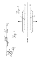
- FIG. 3 of the drawings The preferred apparatus of the instant invention is illustrated schematically in Figure 3 of the drawings.
- a warp beam 31 is passed over guide bar 32 through tensioning device 33 and about a pair of heated rolls 34.
- the heated warp beam 31 is then passed about draw roll 35 through oven member 36 and then into corona charging station 37.
- Warp beam 31 exiting corona charging station 37 is then passed about upper draw roll 38 through the nip formed by lower draw roll member 39 and over idler roll member 40.
- the warp beam 31 passes over idler roll member 40a and thence over guide bar 47 and back into oven member 36 and thence into corona charging station 37.
- Passage of the yarn warp 31 through corona charging station 37 is repeated a plurality of times after which the yarn warp beam is withdrawn over lower draw roll member 39 to take-up beams 46.
- Grids 21 and 22 are connected to high DC voltage power supplies.
- Grids 21 and 22 are composed of thin tungsten wires separated by an air gap of approximately 25 millimeters.
- a charge is injected into a fiber warp by the resulting corona field.
- the grids 21 and 22 may both have a common charge, that is to say both negative or both positive.
- the charge has a high degree of permanence. For example, an olefinic fiber warp single pass corona charged under these conditions retained a charge of greater than 10- 9 coulombs per gram after 400 days. For multi pass corona charge applications to a fiber warp, the charge life is even greater.
- a warp of 60 ends of polypropylene round cross section yarn 7.5 denier per filament (1500 total denier/ 200 Fils yarn) which had been subjected to a draw ratio of 1.25 to 1 is processed on an apparatus substantially as illustrated in Figure 1 of the drawings. Heated rolls 2 are operated at 14 feet per minute at 132°C, the warp beam after passage over the heated rolls being passed about draw roll 5 operated at a speed of 31 feet per minute (9.45 m/min) so as to produce a draw ratio of 1.25 to 1 and then across hot shoe 3, maintained at a temperature of 125°C.
- the yarn is then passed into corona station 4 wherein the top electrode was charged with a negative charge of six kilovolts direct current and the bottom electrode was charged with a positive charge of six kilovolts direct current.
- Nip rolls 6 are operated at 29 feet per minute (8.84 m/min) and take-up roll 7 is also operated at 29 feet per minute (8.84 m/min).
- the effective surface charge density is found to be greater than 10- 9 coulombs per gram, which is equal to a surface voltage of not less than 250 volts.
- Example I The process of Example I is repeated except that a warp of 150 ends of polypropylene trilobal cross section yarn of 6.0 denier per filament is processed.
- the effective surface charge density is found to be greater than 10- 9 coulombs per gram, which is equal to surface voltage of not less than 250 volts.
- Example I The process of Example I is repeated except that draw roll 5 is operated at a speed of 29 feet per minute so that the warp is not being drawn while subjected to corona discharge.
- the effective surface charge density is found to be greater than 10- 9 coulombs per gram which is equal to a surface voltage of not less than 250 volts.
- Example I The process of Example I is repeated except that a tight packed warp of yarn made from a copolymer of tetrabromobisphenol-A and 40/60 iso-terephthalic acid monomers having round cross section and 1.5 denier per filament is employed.
- the effective surface charge density is found to be greater than 10- 9 coulombs per gram, which is equal to a surface voltage of not less than 250 volts.
- a warp of 853 undrawn denier 72 fil polypropylene round cross section yarn is strung up as illustrated in Fig. 3 of the drawings, the warp passing 10 cycles through the oven and corona charging stations, employing the following conditions:
- a wrap of 300 denier 70 fil trilobal polypropylene yarn is strung up as shown in Fig. 3 of the drawings with the following conditions being employed.
- a warp of 600 denier 400 fil round section brominated aromatic polyester yarn is strung up as illustrated in Fig. 3 of the drawings with the following conditions being employed:
- Average surface voltage is found to be (-) 1622 volts after 4 days, indicative of a permanent electret charge.
- Example V to VII which are representative of the multi pass corona charging process of the instant invention, a higher surface voltage is obtained than can be produced by the single pass method as represented by Examples I to IV.
- Example VI is illustrative of the increased charge obtained by increasing the number of cycles. It is assumed that shallow charges are thermally deep trapped and deep charging is increased by means of multiple corona charging passes. A detailed description of the deep charging theory appears in "The Use of Polymers for Electrets" by J. Van Turnhout, Journal of Electrostatics (1975) 147-163.
- a scrim 41 is fed from a feed roll under needle plate member 42.
- Electret continuous filament is fed from a traversing aspirating air jet member 43 onto meshed belt member 44.
- Continuous filament laid by means of traversing air jet member 43 is fed from meshed belt member 44 beneath the needle members of the needle plate member 42 and needle punched into scrim 41 which is also fed beneath the needle member of needle plate member 42. Filament is then punched into scrim 41 to produce filter batting which is taken up on roll member 45.
- the round cross section negatively charged polypropylene electret yarn of Example V is tufted into a 0.5 ounce per square yard (16.95 g/m 2 ) polyester baby diaper scrim fabric by means of a Dilo Maschinen Fabrik, of Eberbach, West Germany needle punch machine.
- the final weight of the needle punch fabric is 3.8 ounces per square yard (128.8 g/m 2 ).
- the round cross section negatively charged yarn of Example V is plied with a yarn prepared according to Example V except that the top and bottom electrodes are given a positive charge of 10 KVDC.
- the plied yarn is then tufted into a 0.5 ounce per square yard (16.95 g/m 2 ) polyester baby diaper scrim fabric by means of a Dilo Maschinen Fabrik of Eberbach, West Germany needle punch machine.
- the fabric is found to be an effective aerosol filter.
- Example A having negatively charged electret yarn needle punched into one face is inverted and a yarn prepared according to Example V except that the top and bottom electrode are given a positive charge of 10 KVDC is tufted into the other face of the fabric. Tufting is again conducted by means of a Dilo Maschinen Fabrik of Eberbach, West Germany needle punch machine. The fabric is found to be an effective aerosol filter.
- An electrical aerosol analyzer was used to measure aerosol member concentrations.
- the instrument which is a model 3030 electrical aerosol analyzer manufactured by Thermo Systems, Inc., St. Paul, Minnesota, draws aerosol at the rate of 50 litres per minute.
- Filter holders made with circular openings which correspond to face velocities of 5.7, 10.3, and 20.2 centimeters per second when the full flow of the instrument was passed through them were prepared and mounted with needle punched fabrics.
- Member concentrations for particles in the size range of 0.02 to 0.75 ⁇ m with an average value of about 0.10 pm were measured using a testing aerosol by lighting a cigarette and allowing it to burn completely while fan stirring the air. Measurements were taken ten minutes after the cigarette had stopped burning.
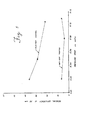
- Fig. 5 of the drawings The results of the particle removal efficiency test are graphically set forth in Fig. 5 of the drawings wherein the needle punched fabric of Example A is evaluated against (1) an identical needle punched fabric devoid of an electrical charge, the electrical charge having been dissipated by treatment with an antistat comprising a 50% aqueous solution of AY-2000 (antistat manufactured and sold by ICI Americas of Wilmington, Delaware) diluted 19 to 1 sprayed on the sample and then allowed to air dry.
- AY-2000 antistat manufactured and sold by ICI Americas of Wilmington, Delaware
- Pressure drop is pressure difference across the filter as measured by means of a water manometer. The result is expressed in centimeters of water gauge.
- the removal efficiency of the electret or charge containing fabric is significantly higher at all face velocities and corresponding pressure drops than the identical needle punched fabric wherein the charge was removed with an antistat.
- the differential between the sample is most pronounced at low pressure drop. Filter qualities for all samples were based on penetration for 0.1 pm particles which are fairly representative of the penetration in the 0.1 to about 0.75 pm range.
Landscapes
- Engineering & Computer Science (AREA)
- Power Engineering (AREA)
- Chemical & Material Sciences (AREA)
- Chemical Kinetics & Catalysis (AREA)
- Physics & Mathematics (AREA)
- Spectroscopy & Molecular Physics (AREA)
- Microelectronics & Electronic Packaging (AREA)
- Textile Engineering (AREA)
- Chemical Or Physical Treatment Of Fibers (AREA)
- Filtering Materials (AREA)
Claims (12)
Applications Claiming Priority (2)
| Application Number | Priority Date | Filing Date | Title |
|---|---|---|---|
| US550069 | 1983-11-08 | ||
| US06/550,069 US4623438A (en) | 1983-11-08 | 1983-11-08 | Electret making process using corona discharge |
Publications (3)
| Publication Number | Publication Date |
|---|---|
| EP0141674A2 EP0141674A2 (de) | 1985-05-15 |
| EP0141674A3 EP0141674A3 (en) | 1985-09-18 |
| EP0141674B1 true EP0141674B1 (de) | 1990-06-13 |
Family
ID=24195613
Family Applications (1)
| Application Number | Title | Priority Date | Filing Date |
|---|---|---|---|
| EP84307668A Expired - Lifetime EP0141674B1 (de) | 1983-11-08 | 1984-11-07 | Verfahren zum Herstellen eines Elektrets und Anordnungen |
Country Status (5)
| Country | Link |
|---|---|
| US (1) | US4623438A (de) |
| EP (1) | EP0141674B1 (de) |
| JP (1) | JPH0663176B2 (de) |
| CA (1) | CA1254854A (de) |
| DE (1) | DE3482523D1 (de) |
Families Citing this family (27)
| Publication number | Priority date | Publication date | Assignee | Title |
|---|---|---|---|---|
| JPS60199970A (ja) * | 1984-03-16 | 1985-10-09 | 東洋紡績株式会社 | エレクトレツト化繊維の製造方法 |
| US4874659A (en) * | 1984-10-24 | 1989-10-17 | Toray Industries | Electret fiber sheet and method of producing same |
| JPS6224610A (ja) * | 1985-07-24 | 1987-02-02 | 東レ株式会社 | エレクトレツト織編物 |
| US5266369A (en) * | 1988-09-21 | 1993-11-30 | Toray Industries, Inc. | Packaging material made of electret material and packaging method |
| US5112690A (en) * | 1990-11-01 | 1992-05-12 | Kimberly-Clark Corporation | Low hydrohead fibrous porous web with improved retentive wettability |
| US5102738A (en) * | 1990-11-01 | 1992-04-07 | Kimberly-Clark Corporation | High hydrohead fibrous porous web with improved retentive absorption and acquision rate |
| US5314737A (en) * | 1991-09-30 | 1994-05-24 | Kimberly-Clark Corporation | Area thinned thin sheet materials |
| US5443886A (en) * | 1991-09-30 | 1995-08-22 | Kimberly-Clark Corporation | Hydrosonically embedded soft thin film materials |
| US5230800A (en) * | 1992-02-20 | 1993-07-27 | Minnesota Mining And Manufacturing Company | Scrim inserted electrostatic fibrous filter web |
| US5336452A (en) * | 1992-09-23 | 1994-08-09 | Kimberly-Clark Corporation | Process for hydrosonically area embossing thin thermoplastic film materials |
| US5370830A (en) * | 1992-09-23 | 1994-12-06 | Kimberly-Clark Corporation | Hydrosonic process for forming electret filter media |
| DE69404736T2 (de) * | 1993-03-09 | 1998-01-08 | Hoechst Celanese Corp | Polymer-Elektrete mit verbesserter Ladungsstabilität |
| CA2124237C (en) | 1994-02-18 | 2004-11-02 | Bernard Cohen | Improved nonwoven barrier and method of making the same |
| CA2136576C (en) | 1994-06-27 | 2005-03-08 | Bernard Cohen | Improved nonwoven barrier and method of making the same |
| WO1996017569A2 (en) | 1994-12-08 | 1996-06-13 | Kimberly-Clark Worldwide, Inc. | Method of forming a particle size gradient in an absorbent article |
| CA2153278A1 (en) | 1994-12-30 | 1996-07-01 | Bernard Cohen | Nonwoven laminate barrier material |
| ZA965786B (en) * | 1995-07-19 | 1997-01-27 | Kimberly Clark Co | Nonwoven barrier and method of making the same |
| US5834384A (en) | 1995-11-28 | 1998-11-10 | Kimberly-Clark Worldwide, Inc. | Nonwoven webs with one or more surface treatments |
| US6537932B1 (en) | 1997-10-31 | 2003-03-25 | Kimberly-Clark Worldwide, Inc. | Sterilization wrap, applications therefor, and method of sterilizing |
| US6054071A (en) * | 1998-01-28 | 2000-04-25 | Xerox Corporation | Poled electrets for gyricon-based electric-paper displays |
| US6365088B1 (en) | 1998-06-26 | 2002-04-02 | Kimberly-Clark Worldwide, Inc. | Electret treatment of high loft and low density nonwoven webs |
| US6805048B2 (en) | 2002-08-30 | 2004-10-19 | 3M Innovative Properties Company | Method of marking a substrate using an electret stencil |
| EP1540678A2 (de) | 2002-08-30 | 2005-06-15 | 3M Innovative Properties Company | Verfahren zur herstellung beschreibbarer und löschbarer artikel und daraus hergestellte gegenstände |
| US20050000642A1 (en) * | 2003-07-03 | 2005-01-06 | 3M Innovative Properties Company | Cling articles |
| GB201015399D0 (en) * | 2010-09-15 | 2010-10-27 | Univ Bolton | Piezoelectric polymer element and production method and apparatus therefor |
| DE102011014202A1 (de) * | 2011-03-16 | 2012-09-20 | Sandler Ag | Filtermedium für die Herstellung plissierter Filter |
| JP5489084B2 (ja) * | 2011-08-12 | 2014-05-14 | Jnc株式会社 | 混繊長繊維不織布 |
Family Cites Families (5)
| Publication number | Priority date | Publication date | Assignee | Title |
|---|---|---|---|---|
| NL160303C (nl) * | 1974-03-25 | 1979-10-15 | Verto Nv | Werkwijze voor het vervaardigen van een vezelfilter. |
| JPS55157801A (en) * | 1979-04-26 | 1980-12-08 | Rikagaku Kenkyusho | Process for producing piezooelectric current collecting high molecular film |
| US4308223A (en) * | 1980-03-24 | 1981-12-29 | Albany International Corp. | Method for producing electret fibers for enhancement of submicron aerosol filtration |
| US4375718A (en) * | 1981-03-12 | 1983-03-08 | Surgikos, Inc. | Method of making fibrous electrets |
| ATE25898T1 (de) * | 1982-03-18 | 1987-03-15 | British Telecomm | Piezoelektrische und pyroelektrische folie. |
-
1983
- 1983-11-08 US US06/550,069 patent/US4623438A/en not_active Expired - Lifetime
-
1984
- 1984-10-30 CA CA000466576A patent/CA1254854A/en not_active Expired
- 1984-11-07 JP JP59233404A patent/JPH0663176B2/ja not_active Expired - Lifetime
- 1984-11-07 EP EP84307668A patent/EP0141674B1/de not_active Expired - Lifetime
- 1984-11-07 DE DE8484307668T patent/DE3482523D1/de not_active Expired - Fee Related
Also Published As
| Publication number | Publication date |
|---|---|
| JPH0663176B2 (ja) | 1994-08-17 |
| EP0141674A2 (de) | 1985-05-15 |
| EP0141674A3 (en) | 1985-09-18 |
| JPS60126373A (ja) | 1985-07-05 |
| DE3482523D1 (de) | 1990-07-19 |
| US4623438A (en) | 1986-11-18 |
| CA1254854A (en) | 1989-05-30 |
Similar Documents
| Publication | Publication Date | Title |
|---|---|---|
| EP0141674B1 (de) | Verfahren zum Herstellen eines Elektrets und Anordnungen | |
| US4944854A (en) | Electret process and products | |
| US4375718A (en) | Method of making fibrous electrets | |
| US4592815A (en) | Method of manufacturing an electret filter | |
| US3360421A (en) | Bonded nonwoven backing material having perforate selvage and carpet made therefrom | |
| US5721180A (en) | Laminate filter media | |
| CA1099870A (en) | Process for the manufacture of filaments from a thermoplastic material | |
| US4652282A (en) | Electretized material for a dust filter | |
| CA1050481A (en) | Method for the manufacture of an electret fibrous filter | |
| US4874659A (en) | Electret fiber sheet and method of producing same | |
| US8021996B2 (en) | Nonwoven web and filter media containing partially split multicomponent fibers | |
| EP0702994B1 (de) | Filtervlies für Gas | |
| RU2238354C2 (ru) | Способ и устройство для изготовления нетканого волокнистого электретного полотна из свободных волокон и полярной жидкости | |
| US4789504A (en) | Electretized material for a dust filter | |
| US3307332A (en) | Electrostatic gas filter | |
| US5871836A (en) | Composite pleated fibrous structures containing split film fibers | |
| DK157286B (da) | Ansigtsmaske samt fremgangsmaade til fremstilling af et fiberbaneelektreret til brug som filterlag i ansigtsmasken | |
| JPH0140141B2 (de) | ||
| GB932482A (de) | ||
| WO2016081937A1 (en) | In-situ charging fiber spinning method for producing a nonwoven electret | |
| JPH02104765A (ja) | エレクトレット不織布の製造方法 | |
| JP3228343B2 (ja) | エレクトレットフィルターの製造方法 | |
| EP0182512B1 (de) | Elektretfiberfolie und Verfahren zu deren Herstellung | |
| JPS6123288B2 (de) | ||
| JP2535325B2 (ja) | ポリオレフインエレクトレツト織編物の製造方法 |
Legal Events
| Date | Code | Title | Description |
|---|---|---|---|
| PUAI | Public reference made under article 153(3) epc to a published international application that has entered the european phase |
Free format text: ORIGINAL CODE: 0009012 |
|
| AK | Designated contracting states |
Designated state(s): DE FR GB NL |
|
| PUAL | Search report despatched |
Free format text: ORIGINAL CODE: 0009013 |
|
| AK | Designated contracting states |
Designated state(s): DE FR GB NL |
|
| 17P | Request for examination filed |
Effective date: 19860219 |
|
| 17Q | First examination report despatched |
Effective date: 19871202 |
|
| GRAA | (expected) grant |
Free format text: ORIGINAL CODE: 0009210 |
|
| AK | Designated contracting states |
Kind code of ref document: B1 Designated state(s): DE FR GB NL |
|
| REF | Corresponds to: |
Ref document number: 3482523 Country of ref document: DE Date of ref document: 19900719 |
|
| ET | Fr: translation filed | ||
| PLBE | No opposition filed within time limit |
Free format text: ORIGINAL CODE: 0009261 |
|
| STAA | Information on the status of an ep patent application or granted ep patent |
Free format text: STATUS: NO OPPOSITION FILED WITHIN TIME LIMIT |
|
| 26N | No opposition filed | ||
| PGFP | Annual fee paid to national office [announced via postgrant information from national office to epo] |
Ref country code: NL Payment date: 19921130 Year of fee payment: 9 |
|
| PG25 | Lapsed in a contracting state [announced via postgrant information from national office to epo] |
Ref country code: NL Effective date: 19940601 |
|
| NLV4 | Nl: lapsed or anulled due to non-payment of the annual fee | ||
| PGFP | Annual fee paid to national office [announced via postgrant information from national office to epo] |
Ref country code: GB Payment date: 19961009 Year of fee payment: 13 |
|
| PGFP | Annual fee paid to national office [announced via postgrant information from national office to epo] |
Ref country code: FR Payment date: 19961113 Year of fee payment: 13 |
|
| PGFP | Annual fee paid to national office [announced via postgrant information from national office to epo] |
Ref country code: DE Payment date: 19961128 Year of fee payment: 13 |
|
| PG25 | Lapsed in a contracting state [announced via postgrant information from national office to epo] |
Ref country code: GB Free format text: LAPSE BECAUSE OF NON-PAYMENT OF DUE FEES Effective date: 19971107 |
|
| PG25 | Lapsed in a contracting state [announced via postgrant information from national office to epo] |
Ref country code: FR Free format text: THE PATENT HAS BEEN ANNULLED BY A DECISION OF A NATIONAL AUTHORITY Effective date: 19971130 |
|
| GBPC | Gb: european patent ceased through non-payment of renewal fee |
Effective date: 19971107 |
|
| PG25 | Lapsed in a contracting state [announced via postgrant information from national office to epo] |
Ref country code: DE Free format text: LAPSE BECAUSE OF NON-PAYMENT OF DUE FEES Effective date: 19980801 |
|
| REG | Reference to a national code |
Ref country code: FR Ref legal event code: ST |