EP0141426B1 - Plug valve - Google Patents
Plug valve Download PDFInfo
- Publication number
- EP0141426B1 EP0141426B1 EP84113442A EP84113442A EP0141426B1 EP 0141426 B1 EP0141426 B1 EP 0141426B1 EP 84113442 A EP84113442 A EP 84113442A EP 84113442 A EP84113442 A EP 84113442A EP 0141426 B1 EP0141426 B1 EP 0141426B1
- Authority
- EP
- European Patent Office
- Prior art keywords
- sliding plug
- chamber
- chambers
- plug
- inlet
- Prior art date
- Legal status (The legal status is an assumption and is not a legal conclusion. Google has not performed a legal analysis and makes no representation as to the accuracy of the status listed.)
- Expired
Links
- 238000005192 partition Methods 0.000 abstract description 6
- 239000012530 fluid Substances 0.000 description 5
- XLYOFNOQVPJJNP-UHFFFAOYSA-N water Substances O XLYOFNOQVPJJNP-UHFFFAOYSA-N 0.000 description 5
- 230000006870 function Effects 0.000 description 2
- 238000004140 cleaning Methods 0.000 description 1
- 238000010276 construction Methods 0.000 description 1
- 230000000694 effects Effects 0.000 description 1
- 230000009993 protective function Effects 0.000 description 1
- 238000007789 sealing Methods 0.000 description 1
- 230000003595 spectral effect Effects 0.000 description 1
Images

Classifications
-
- F—MECHANICAL ENGINEERING; LIGHTING; HEATING; WEAPONS; BLASTING
- F16—ENGINEERING ELEMENTS AND UNITS; GENERAL MEASURES FOR PRODUCING AND MAINTAINING EFFECTIVE FUNCTIONING OF MACHINES OR INSTALLATIONS; THERMAL INSULATION IN GENERAL
- F16K—VALVES; TAPS; COCKS; ACTUATING-FLOATS; DEVICES FOR VENTING OR AERATING
- F16K11/00—Multiple-way valves, e.g. mixing valves; Pipe fittings incorporating such valves
- F16K11/02—Multiple-way valves, e.g. mixing valves; Pipe fittings incorporating such valves with all movable sealing faces moving as one unit
- F16K11/08—Multiple-way valves, e.g. mixing valves; Pipe fittings incorporating such valves with all movable sealing faces moving as one unit comprising only taps or cocks
- F16K11/085—Multiple-way valves, e.g. mixing valves; Pipe fittings incorporating such valves with all movable sealing faces moving as one unit comprising only taps or cocks with cylindrical plug
- F16K11/0853—Multiple-way valves, e.g. mixing valves; Pipe fittings incorporating such valves with all movable sealing faces moving as one unit comprising only taps or cocks with cylindrical plug having all the connecting conduits situated in a single plane perpendicular to the axis of the plug
-
- Y—GENERAL TAGGING OF NEW TECHNOLOGICAL DEVELOPMENTS; GENERAL TAGGING OF CROSS-SECTIONAL TECHNOLOGIES SPANNING OVER SEVERAL SECTIONS OF THE IPC; TECHNICAL SUBJECTS COVERED BY FORMER USPC CROSS-REFERENCE ART COLLECTIONS [XRACs] AND DIGESTS
- Y10—TECHNICAL SUBJECTS COVERED BY FORMER USPC
- Y10T—TECHNICAL SUBJECTS COVERED BY FORMER US CLASSIFICATION
- Y10T137/00—Fluid handling
- Y10T137/8593—Systems
- Y10T137/86493—Multi-way valve unit
- Y10T137/86839—Four port reversing valves
-
- Y—GENERAL TAGGING OF NEW TECHNOLOGICAL DEVELOPMENTS; GENERAL TAGGING OF CROSS-SECTIONAL TECHNOLOGIES SPANNING OVER SEVERAL SECTIONS OF THE IPC; TECHNICAL SUBJECTS COVERED BY FORMER USPC CROSS-REFERENCE ART COLLECTIONS [XRACs] AND DIGESTS
- Y10—TECHNICAL SUBJECTS COVERED BY FORMER USPC
- Y10T—TECHNICAL SUBJECTS COVERED BY FORMER US CLASSIFICATION
- Y10T137/00—Fluid handling
- Y10T137/8593—Systems
- Y10T137/86493—Multi-way valve unit
- Y10T137/86863—Rotary valve unit
Definitions
- the invention relates to a rotary slide valve, the cylindrical slide valve with its axis of rotation mounted transversely to the flow and abutting a fixed coaxial cylinder of approximately the same size, the openings through which the fluid is controlled are controlled by openings and wall parts of the slide valve, and the slide valve having a larger diameter Outside cylinder is coaxially surrounded, each having an inlet and outlet on opposite sides, so that in the normal position of the slide the inlet of the first side is connected to the outlet of the second side and the outlet of the first side is connected to the inlet of the second side and in Deflection position, the inlets are connected to one another and the outlets are connected to one another, in the latter position a first stream flowing through a first inner chamber of the slide and a second stream flowing through an axially adjacent second inner chamber of the slide, the dividing wall of which to the adjacent chamber is approximately right is at an angle to the axis of rotation of the slide.
- Such a rotary valve is known from DE-A-3 147 511.
- the annular space between the outer cylinder and the rotary valve or stationary cylinder is traversed by the outward and return flow, and in the position in which the currents cross, a current flows through a first chamber of the slide and the second Stream through a second chamber.
- the slide rests with radial wall parts on the inner wall of the outer cylinder, i.e. the slide works with the outer cylinder, so that the outer cylinder must be manufactured with high precision. Since the four connecting pieces are attached to the outer cylinder, thrust and tensile forces are easily transmitted from the connecting piece to the outer cylinder, so that a reliable function of the rotary valve is not guaranteed.
- the object of the invention is to improve a rotary valve of the type mentioned in such a way that the functional reliability and the tightness are increased and the wear is reduced.
- the slide does not touch the outer cylinder and the currents run through the interior of the slide in both rotational positions, that the slide interior is divided in the axial direction into three chambers, one of which middle the first flow and the two outer the lead second current, and that in one position, in particular the deflection position, all three chambers and in the second position, in particular the normal position, only the middle chamber flows through.
- the slide interior is divided in the axial direction into three chambers, of which a middle one carries the first stream and the two outer ones carry the second stream.
- the rotary valve is always evenly loaded by the medium flows, in particular by the water flows. Tilting around an axis perpendicular to the axis of rotation is avoided with a high degree of certainty, and the bearings are thus not subjected to any great stress. This also leads to a further increase in tightness and a reduction in wear.
- the middle chamber is divided into two partial chambers by a middle partition wall parallel to the axis of rotation or running through it. It is preferably proposed that in the normal position one subchamber carry one stream and the second subchamber carry the second stream and in the deflection position both subchambers carry one of the two streams together.
- the middle chamber has a greater height than one of the two outer chambers.
- the lateral chambers can have approximately the same height and the central chamber approximately the same have twice the height of an outer chamber.
- the annular space between the slide and the outer cylinder have partition walls which prevent the medium from flowing from the connections in both slide positions.
- Such a rotary slide device can be used particularly advantageously in the lines to a heat exchanger which has freely movable brushes in its (condenser) tubes which can be moved back and forth with reversal of the water flow and thus clean the tubes of the heat exchanger.
- the device forming a shut-off device is usually called a rotary valve and more precisely a roller valve, although the sealing body, which is arranged on the inside in a rotatable manner, is itself also called a rotary valve or roller valve.
- the device has a roller-shaped or cylindrical slide 1, which is designed as a hollow cylinder and whose axis of rotation is perpendicular to the direction of flow and in particular perpendicular.
- the cylindrical interior of the slide 1 is divided into three cylindrical chambers by two, in particular horizontal, transverse walls 3, 4, which are arranged at right angles to the axis of rotation 2, the end faces of the slide cylinder also being closed off by walls.
- the uppermost first chamber 5 and the lowermost third chamber 6 have the same height, and the middle second chamber 7 is twice as high as one of the other two chambers 5, 6.
- a particularly vertical partition 8 is fastened running through the axis of rotation 2, which in the normal position shown in FIGS. 1, 4 and 5 is parallel to the two flow directions.
- the rotary valve 1 is mounted within an inner fixed cylinder 9, whose inner diameter is only slightly larger than the outer diameter of the slide 1 and which is coaxially surrounded by an outer cylinder 10, which forms an annular space 11 with the cylinder 9, which by radial partitions 12 in four sectors of equal size is divided.
- a connecting piece is attached to each of these four spectral annular subspaces 11a, 11b, 11c, 11d, each of which extends over 90 degrees, an inlet E 1 and an outlet A being connected in parallel on the first side and on the opposite side second side, an inlet E2 and an outlet A 2 . Inlets and outlets A, and E2 as well as E 1 and A 2 are aligned.
- the inner, fixed cylinder 9 has four openings 9a, 9b, 9c, 9d at the level of all three chambers, which connect the cylinder interior and the slide interior to the annular spaces 11 to 11d (FIG. 6). These openings 9a to 9d are controlled by the slide 1, which has openings 1a to 1f in its cylindrical wall, of which the openings 1a-1d at the level of the central chamber and the openings 1e and 1f at the level of the upper and lower Chamber 5, 6 are arranged. In the normal position shown in FIGS. 1, 4 and 5, the upper chamber 5 and the lower chamber 6 are closed by the slide 1 (FIG.
- the partition in two subchambers 7a, 7b 8 divided middle chamber with the first sub-chamber connects the inlet E 1 to the outlet A 2 and the second sub-chamber 7a connects the inlet E2 with the outlet A 1 , so that both flows of the fluid or water flow parallel to one another.
- the slide 1 is rotated by 45 ° by an actuator, as a result of which the Partial space 11a is connected to the partial space 11c via both partial chambers 7a, 7b and thus the fluid flows from the inlet E 1 through the middle chamber to the inlet E2, which can now be called the outlet.
- the two other chambers 5, 6 are also used, since their openings 1e, 1f are opened by the slide and thus the interior spaces of the chambers 5, 6 are connected to the partial annular spaces 11d and 11b.
- Half the fluid backflow thus flows through the first chamber and the second half over the third chamber from A 2 to A, and crosses the outflow flowing through the middle chamber.
- a heat exchanger 13 is connected, in the condenser tubes 14, not shown, freely movable cleaning brushes are moved back and forth by the fluid flow, in particular by the water flow, and stop their movement in collecting sleeves 15 at the ends of the condenser tubes .
- the flow in the condenser tubes is reversed, and thus in the condenser tubes located brushes moved over the entire length of the tubes and moved back after resetting the slide 1, whereby deposits in the tubes are removed.
- the nominal size of the connecting piece is 50-700 mm and the diameter of the housing (outer cylinder) is 400-2400 mm.
Landscapes
- Engineering & Computer Science (AREA)
- General Engineering & Computer Science (AREA)
- Mechanical Engineering (AREA)
- Multiple-Way Valves (AREA)
- Sliding Valves (AREA)
- Details Of Valves (AREA)
- Feeding And Controlling Fuel (AREA)
- Magnetically Actuated Valves (AREA)
Abstract
Description
Die Erfindung betrifft einen Drehschieber, dessen zylindrischer Schieber mit seiner Drehachse quer zur Strömung gelagert und an einem feststehenden koaxialen Zylinder etwa gleicher Größe anliegt, dessen das Strömungsmittel durchlassende Öffnungen durch Öffnungen und Wandteile des Schiebers gesteuert sind, und der Schieber von einem einen größeren Durchmesser aufweisenden Außenzylinder koaxial umgeben ist, der auf gegenüberliegenden Seiten jeweils einen Ein-und Auslaß aufweist, so daß in Normalstellung des Schiebers der Einlaß der ersten Seite mit dem Auslaß der zweiten Seite und der Auslaß der ersten Seite mit dem Einlaß der zweiten Seite verbunden ist und in Umlenkstellung die Einlässe miteinander und die Auslässe miteinander verbunden sind, wobei in letzterer Stellung ein erster Strom durch eine erste Innenkammer des Schiebers und ein zweiter Strom durch eine in Axialrichtung daran angrenzende zweite Innenkammer des Schiebers fließt, deren Trennwand zur benachbarten Kammer etwa rechtwinklig zur Drehachse des Schiebers ist.The invention relates to a rotary slide valve, the cylindrical slide valve with its axis of rotation mounted transversely to the flow and abutting a fixed coaxial cylinder of approximately the same size, the openings through which the fluid is controlled are controlled by openings and wall parts of the slide valve, and the slide valve having a larger diameter Outside cylinder is coaxially surrounded, each having an inlet and outlet on opposite sides, so that in the normal position of the slide the inlet of the first side is connected to the outlet of the second side and the outlet of the first side is connected to the inlet of the second side and in Deflection position, the inlets are connected to one another and the outlets are connected to one another, in the latter position a first stream flowing through a first inner chamber of the slide and a second stream flowing through an axially adjacent second inner chamber of the slide, the dividing wall of which to the adjacent chamber is approximately right is at an angle to the axis of rotation of the slide.
Ein solcher Drehschieber ist aus der DE-A-3 147 511 bekannt. Bei diesem bekannten Drehschieber ist in der Normalstellung der Ringraum zwischen Außenzylinder und Drehschieber bzw. festehendem Zylinder von dem Hin- und Rückstrom durchflossen, und in der Stellung, in der die Ströme sich kreuzen, fließt ein Strom durch eine erste Kammer des Schiebers und der zweite Strom durch eine zweite Kammer. Der Schieber liegt mit radialen Wandteilen an der Innenwandung des Außenzylinders an, d.h. der Schieber arbeitet mit dem Außenzylinder zusammen, so daß der Außenzylinder mit hoher Präzision gefertigt sein muß. Da am Außenzylinder die vier Anschlußstutzen befestigt sind, werden Schub- und Zugkräfte leicht von den Anschlußstutzen auf den Außenzylinder übertragen, so daß eine sichere Funktion des Drehschiebers nicht gewährleistet ist. Es kann sowohl zu Verschleißerscheinungen zwischen Drehschieber und Innenwandung des Außenzylinders als auch zu einem Verklemmen und Undichtigkeiten kommen. Auch wird in der kreuzenden Stellung der Drehschieber aufgrund der durch die beiden Kammern hindurchfließenden Wasserströme ungleichmäßig zu einer Kipplage hin balastet, so daß auch hierdurch Verschleiß und Verklemmen als auch Undichtigkeiten auftreten können und die Lager stark belastet werden.Such a rotary valve is known from DE-A-3 147 511. In this known rotary valve in the normal position, the annular space between the outer cylinder and the rotary valve or stationary cylinder is traversed by the outward and return flow, and in the position in which the currents cross, a current flows through a first chamber of the slide and the second Stream through a second chamber. The slide rests with radial wall parts on the inner wall of the outer cylinder, i.e. the slide works with the outer cylinder, so that the outer cylinder must be manufactured with high precision. Since the four connecting pieces are attached to the outer cylinder, thrust and tensile forces are easily transmitted from the connecting piece to the outer cylinder, so that a reliable function of the rotary valve is not guaranteed. There may be signs of wear between the rotary valve and the inner wall of the outer cylinder as well as jamming and leaks. Also, in the crossing position, the rotary valve is unevenly balanced due to the water currents flowing through the two chambers towards a tipping position, so that wear and jamming as well as leaks can also occur and the bearings are heavily loaded.
Aus der US-A-3 973 592 ist ein Ventil mit einem kükenförmigen Stellglied bekannt. Zu seiner Funktion benötigt dieses Ventil im Innern neben dem Stellglied zusätzlich eine seitliche Kammer (78), die in radialer Richtung Platz benötigt und damit die für die Strömung benötigte Öffnung bzw. den Strömungsquerschnitt verkleinert, so daß ein hoher Druckverlust entsteht. Die Konstruktion ist darüber hinaus komplizierter und hat eine nicht genügende Abdichtung zwischen Vor- und Rücklauf.From US-A-3 973 592 a valve with a plug-shaped actuator is known. In order to function, this valve requires in addition to the actuator an additional lateral chamber (78) which requires space in the radial direction and thus reduces the opening or the flow cross section required for the flow, so that a high pressure loss occurs. The construction is also more complicated and has an insufficient seal between the flow and return.
Aufgabe der Erfindung ist es, einen Drehschieber der eingangs genannten Art derart zu verbessern, daß die Funktionssicherheit als auch die Dichtigkeit erhöht und der Verschleiß verringert werden.The object of the invention is to improve a rotary valve of the type mentioned in such a way that the functional reliability and the tightness are increased and the wear is reduced.
Diese Aufgabe wird erfindungsgemäß dadurch gelöst, daß der Schieber den Außenzylinder nicht berührt und in beiden Drehstellungen die Ströme durch die Innenräume des Schiebers verlaufen, daß das Schieberinnere in Axialrichtung in drei Kammern unterteilt ist, von denen eine mittlere den ersten Strom und die beiden äußeren den zweiten Strom führen, und daß in einer Stellung, insbesondere der Umlenkstellung, alle drei Kammern und in der zweiten Stellung, insbesondere der Normalstellung, nur die mittlere Kammer durchflossen ist bzw. sind.This object is achieved in that the slide does not touch the outer cylinder and the currents run through the interior of the slide in both rotational positions, that the slide interior is divided in the axial direction into three chambers, one of which middle the first flow and the two outer the lead second current, and that in one position, in particular the deflection position, all three chambers and in the second position, in particular the normal position, only the middle chamber flows through.
Dadurch, daß der Drehschieber nicht mehr mit den Außenzylindern, sondern nur noch mit dem feststehenden koaxialen inneren Zylinder zusammenarbeitet, wirken sich Veränderungen des Außenzylinders auf die Funktionstüchtigkeit, auf den Verschleiß und die Dichtigkeit nicht aus. Der Außenzylinder nimmt die von den Anschlußstutzen ausgeübten Kräfte auf und gibt sie nach innen nicht weiter, so daß der Außenzylinder nur noch eine Anschluß- und Schutzfunktion hat, während der innere walzenförmige Schieber in hoher Präzision mit dem inneren feststehenden Zylinder zusammenarbeitet und hierbei eine hohe Dichtigkeit erreicht und geringem Verschleiß unterliegt.Because the rotary valve no longer works with the outer cylinders, but only with the stationary coaxial inner cylinder, changes in the outer cylinder have no effect on functionality, wear and tightness. The outer cylinder absorbs the forces exerted by the connecting piece and does not pass it on to the inside, so that the outer cylinder only has a connection and protective function, while the inner cylindrical slide works together with the inner fixed cylinder with high precision and a high level of tightness reached and subject to low wear.
Besonders vorteilhaft ist es, daß das Schieberinnere in Axialrichtung in drei Kammern unterteilt ist, von denen eine mittlere den ersten Strom und die beiden äußeren den zweiten Strom führen. Hierdurch ist erreichbar, daß der Drehschieber durch die Mediumströme, insbesondere durch die Wasserströme, stets gleichmäßig belastet wird. Ein Verkippen um eine zur Drehachse senkrechte Achse wird mit hoher Sicherheit vermieden, und damit werden die Lager wenig belastet. Auch führt dies zu einer weiteren Erhöhung der Dichtigkeit und Verringerung des Verschleißes. Besonders vorteilhaft ist es, wenn die mittlere Kammer durch eine mittlere, zur Drehachse parallele oder durch diese verlaufende Trennwand in zwei Teilkammern unterteilt ist. Vorzugsweise wird vorgeschlagen, daß in der Normalstellung eine Teilkammer einen Strom und die zweite Teilkammer den zweiten Strom führt und in der Umlenkstellung beide Teilkammern zusammen einen der zwei Ströme führen.It is particularly advantageous that the slide interior is divided in the axial direction into three chambers, of which a middle one carries the first stream and the two outer ones carry the second stream. In this way it can be achieved that the rotary valve is always evenly loaded by the medium flows, in particular by the water flows. Tilting around an axis perpendicular to the axis of rotation is avoided with a high degree of certainty, and the bearings are thus not subjected to any great stress. This also leads to a further increase in tightness and a reduction in wear. It is particularly advantageous if the middle chamber is divided into two partial chambers by a middle partition wall parallel to the axis of rotation or running through it. It is preferably proposed that in the normal position one subchamber carry one stream and the second subchamber carry the second stream and in the deflection position both subchambers carry one of the two streams together.
Um in den beiden Drehstellungen des Schiebers gleich große Durchflußquerschnitte für beide Ströme zu erhalten, wird vorgeschlagen, daß in Achsrichtung gemessen die mittlere Kammer eine größere Höhe aufweist als eine der beiden äußeren Kammern. Ferner können hierzu die seitlichen Kammern etwa dieselbe Höhe haben und die mittlere Kammer etwa die doppelte Höhe einer äußeren Kammer haben.In order to obtain flow cross sections of the same size for both streams in the two rotary positions of the slide, it is proposed that, measured in the axial direction, the middle chamber has a greater height than one of the two outer chambers. Furthermore, the lateral chambers can have approximately the same height and the central chamber approximately the same have twice the height of an outer chamber.
Um sicherzustellen, daß alle Ströme stets nur durch den Innenraum des Schiebers fließen, wird vorgeschlagen, daß der Ringraum zwischen Schieber und Außenzylinder Trennwände aufweist, die ein Strömen des Mediums von den Anschlüssen in beiden Schieberstellungen verhindern.In order to ensure that all flows always flow only through the interior of the slide, it is proposed that the annular space between the slide and the outer cylinder have partition walls which prevent the medium from flowing from the connections in both slide positions.
Besonders vorteilhaft ist eine solche Drehschiebervorrichtung in den Leitungen zu einem Wärmetauscher verwendbar, der in seinen (Kondensator)Rohren frei bewegliche Bürsten aufweist, die mit Umkehrung des Wasserstroms hin- und herbeweglich sind und damit die Rohre des Wärmetauschers reinigen.Such a rotary slide device can be used particularly advantageously in the lines to a heat exchanger which has freely movable brushes in its (condenser) tubes which can be moved back and forth with reversal of the water flow and thus clean the tubes of the heat exchanger.
Ein Ausführungsbeispiel der Erfindung ist in den Zeichnungen dargestellt und wird im folgenden näher beschrieben. Es zeigen:
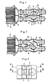
- Fig. 1 einen waagerechten Schnitt durch die Vorrichtung in Normalstellung des Schiebers und mit angeschlossenem Wärmetauscher;
- Fig. 2 einen Schnitt nach Fig. 1 in Umlenkstellung;
- Fig. 3 einen senkrechten Schnitt durch die Vorrichtung quer zur Strömungsrichtung;
- Fig. 4 einen Schnitt nach B-B in Fig. 3 in Normalstellung des Schiebers;
- Fig. 5 einen Schnitt nach A-A in Fig. 3 in Normalstellung;
- Fig. 6 einen Schnitt nach B-B in Umlenkstellung; und
- Fig. 7 einen Schnitt nach A-A in Umlenkstellung.
- Figure 1 is a horizontal section through the device in the normal position of the slide and with a connected heat exchanger.
- FIG. 2 shows a section according to FIG. 1 in the deflection position;
- 3 shows a vertical section through the device transversely to the direction of flow;
- 4 shows a section according to BB in FIG. 3 in the normal position of the slide;
- 5 shows a section according to AA in FIG. 3 in the normal position;
- 6 shows a section according to BB in the deflection position; and
- Fig. 7 shows a section according to AA in the deflection position.
Die ein Absperrorgan bildende Vorrichtung wird üblicherweise Drehschieber und genauer Walzenschieber genannt, obwohl der innen drehbar angeordnete Dichtkörper selber auch Drehschieber bzw. Walzenschieber genannt wird. Die Vorrichtung weist einen walzenförmigen bzw. zylindrischen Schieber 1 auf, der als Hohlzylinder ausgeführt ist und dessen Drehachse rechtwinklig zur Strömungsrichtung und insbesondere senkrecht ist. Der zylindrische Innenraum des Schiebers 1 ist durch zwei rechtwinklig zur Drehachse 2 angeordnete, insbesondere waagerechte Querwände 3,4 in drei zylindrische Kammern unterteilt, wobei auch die Stirnseiten des Schieberzylinders durch Wände abgeschlossen sind. Die oberste erste Kammer 5 und die unterste dritte Kammer 6 weisen dieselbe Höhe auf, und die mittlere zweite Kammer 7 ist doppelt so hoch wie eine der beiden anderen Kammern 5, 6.The device forming a shut-off device is usually called a rotary valve and more precisely a roller valve, although the sealing body, which is arranged on the inside in a rotatable manner, is itself also called a rotary valve or roller valve. The device has a roller-shaped or
In der mittleren Kammer 7 ist eine insbesondere senkrechte Trennwand 8 durch die Drehachse 2 verlaufend befestigt, die in der in Fig. 1,4 und 5 dargestellten Normalstellung parallel zu den beiden Strömungsrichtungen steht. Der Drehschieber 1 ist innerhalb eines inneren feststehenden Zylinders 9 gelagert, dessen Innendurchmesser nur wenig größer ist als der Außendurchmesser des Schiebers 1 und der von einem Außenzylinder 10 koaxial umgeben ist, der mit dem Zylinder 9 einen Ringraum 11 bildet, der durch radiale Trennwände 12 in vier gleich große Sektoren aufgeteilt ist. An jedem dieser vier sektroförmigen Ringteilräume 11 a, 11b, 11c, 11d, die sich jeweils über 90 Grad erstrecken, ist ein Anschlußstutzen befestigt, wobei auf der ersten Seite ein Einlaß E1 und dazu parallel ein Auslaß A, angeschlossen ist und auf der gegenüberliegenden zweiten Seite ein Einlaß E2 und ein Auslaß A2. Die Einlässe und Auslässe A, und E2 als auch E1 und A2 fluchten miteinander.In the middle chamber 7, a particularly vertical partition 8 is fastened running through the axis of rotation 2, which in the normal position shown in FIGS. 1, 4 and 5 is parallel to the two flow directions. The
Der innere, feststehende Zylinder 9 weist in Höhe aller drei Kammern vier Öffnungen 9a, 9b, 9c, 9d auf, die den Zylinderinnenraum als auch den Schieberinnenraum jeweils mit den Ringräumen 11 bis 11d verbinden (Fig. 6). Diese Öffnungen 9a bis 9d werden durch den Schieber 1 gesteuert, wobei dieser in seiner zylindrischen Wandung Öffnungen 1a bis 1f aufweist, von denen die Öffnungen 1a-1d in Höhe der mittleren Kammer und die Öffnungen 1 e und 1f jeweils in Höhe der oberen und unteren Kammer 5, 6 angeordnet sind. In der in Fig. 1, 4 und 5 dargestellten Normalstellung sind die obere Kammer 5 und die untere Kammer 6 durch den Schieber 1 geschlossen (Fig. 5) und die mittlere Kammer 7 geöffnet, wobei die in zwei Teilkammern 7a, 7b durch die Trennwand 8 unterteilte mittlere Kammer mit der ersten Teilkammer den Einlaß E1 mit dem Auslaß A2 verbindet und die zweite Teilkammer 7a den Einlaß E2 mid den Auslaß A1, so daß beide Ströme des Fluids oder Wassers zueinander parallel aneinander vorbeifließen.The inner, fixed
Soll für eine meist nur kurze Zeit der Einlaß EI mit dem Einlaß E2 und der Auslaß A2 mit dem Auslaß A, verbunden werden, so daß die Ströme sich kreuzen, so wird durch einen Stellantrieb der Schieber 1 um 45° gedreht, wodurch der Teilraum 11a mit dem Teilraum 11c über beide Teilkammern 7a, 7b miteinander verbunden sind und somit das Fluid vom Einlaß E1 durch die mittlere Kammer zum Einlaß E2, der nunmehr Auslaß genannt werden kann, fließt. In dieser Drehstellung des Schiebers 1 werden auch die beiden anderen Kammern 5, 6 genutzt, da deren Öffnungen 1e, 1f durch den Schieber geöffnet werden und damit die Innenräume der Kammern 5,6 mit den Teilringräumen 11 d und 11 b verbunden werden. Der halbe Fluidrückstrom fließt damit über die erste Kammer und die zweite Hälfte über die dritte Kammer von A2 nach A, und kreuzt den durch die mittlere Kammer fließenden Hinstrom.If the inlet E I is to be connected to the inlet E2 and the outlet A 2 to the outlet A for a mostly short time, so that the currents intersect, the
An dem Einlaß E2 und dem Auslaß A2 ist ein Wärmetauscher 13 angeschlossen, in dessen Kondensatorrohren 14 nicht dargestellte, frei bewegliche Reinigungsbürsten durch den Fluidstrom, insbesondere durch den Wasserstrom hin- und herbewegt werden und in Auffanghülsen 15 an den Enden der Kondensatorrohre ihre Bewegung stoppen. Durch ein kurzzeitiges Umkehren der Strömung durch den Wärmetauscher wird die Strömung in den Kondensatorrohren umgekehrt, und damit werden die in den Kondensatorrohren befindlichen Bürsten über die gesamte Länge der Rohre hindurchbewegt und nach Rückstellung des Schiebers 1 wieder zurückbewegt, wodurch Ablagerungen in den Rohren entfernt werden. Im Normalfall beträgt die Nennweite der Anschlußstutzen 50 -700 mm und der Durchmesser des Gehäuses (Außenzylinder) 400-2400 mm.At the inlet E2 and the outlet A 2 , a
Claims (7)
Priority Applications (1)
| Application Number | Priority Date | Filing Date | Title |
|---|---|---|---|
| AT84113442T ATE34440T1 (en) | 1983-11-09 | 1984-11-07 | ROTARY VALVE. |
Applications Claiming Priority (2)
| Application Number | Priority Date | Filing Date | Title |
|---|---|---|---|
| DE3340400A DE3340400C2 (en) | 1983-11-09 | 1983-11-09 | Rotary valve |
| DE3340400 | 1983-11-09 |
Publications (3)
| Publication Number | Publication Date |
|---|---|
| EP0141426A2 EP0141426A2 (en) | 1985-05-15 |
| EP0141426A3 EP0141426A3 (en) | 1985-11-27 |
| EP0141426B1 true EP0141426B1 (en) | 1988-05-18 |
Family
ID=6213776
Family Applications (1)
| Application Number | Title | Priority Date | Filing Date |
|---|---|---|---|
| EP84113442A Expired EP0141426B1 (en) | 1983-11-09 | 1984-11-07 | Plug valve |
Country Status (5)
| Country | Link |
|---|---|
| US (1) | US4623001A (en) |
| EP (1) | EP0141426B1 (en) |
| AT (1) | ATE34440T1 (en) |
| DE (2) | DE3340400C2 (en) |
| ZA (1) | ZA848678B (en) |
Families Citing this family (14)
| Publication number | Priority date | Publication date | Assignee | Title |
|---|---|---|---|---|
| US4653537A (en) * | 1986-03-20 | 1987-03-31 | Water Services Of America, Inc. | Fluid flow diverter valve with improved chamber arrangement |
| US5047216A (en) * | 1988-02-22 | 1991-09-10 | Delta Projects Inc. | Apparatus for recovering elemental sulphur |
| US5911243A (en) * | 1997-10-10 | 1999-06-15 | Univalve Llc | Multiport conversion system for butterfly valve |
| JP4644517B2 (en) * | 2005-04-19 | 2011-03-02 | 伸和コントロールズ株式会社 | 4-port automatic switching valve |
| KR101453288B1 (en) * | 2008-07-14 | 2014-10-21 | 한라비스테온공조 주식회사 | Flow Control Valve And Air conditioner for an Automobile equipped with same |
| KR101422610B1 (en) * | 2008-07-14 | 2014-07-23 | 한라비스테온공조 주식회사 | Flow Control Valve And Air conditioner for an Automobile equipped with same |
| US9205720B2 (en) * | 2008-03-27 | 2015-12-08 | Halla Visteon Climate Control Corporation | Flow control valve and air conditioner for an automobile equipped with same |
| IL192499A (en) * | 2008-06-29 | 2013-03-24 | S E S Solar Energy Solutions Ltd | Solar collector |
| US8961281B2 (en) * | 2009-09-28 | 2015-02-24 | Entsorgafin S.P.A. | Ventilation group for flow reversal |
| US9068501B2 (en) | 2013-02-01 | 2015-06-30 | Ford Global Technologies, Llc | Branch communication valve for a twin scroll turbocharger |
| US20150087220A1 (en) * | 2013-09-23 | 2015-03-26 | Vinylast, Inc. | Barrel-style coil-actuated vent |
| WO2018053635A1 (en) | 2016-09-21 | 2018-03-29 | Cgc Group Of Companies Incorporated | Flow control valve and hydronic system |
| WO2019058242A1 (en) * | 2017-09-21 | 2019-03-28 | Cgc Group Of Companies Incorporated | Flow control valve and hydronic system |
| US10683727B1 (en) * | 2018-12-13 | 2020-06-16 | Cameron International Corporation | Valve for mineral extraction systems |
Family Cites Families (11)
| Publication number | Priority date | Publication date | Assignee | Title |
|---|---|---|---|---|
| DE312210C (en) * | ||||
| US21524A (en) * | 1858-09-14 | Combination steam-valve | ||
| US1329881A (en) * | 1919-02-12 | 1920-02-03 | John F Bloom | Valve |
| GB335111A (en) * | 1929-11-12 | 1930-09-18 | Holden & Brooke Ltd | Improvements in or relating to hot water heating systems |
| US2239139A (en) * | 1939-09-18 | 1941-04-22 | George S Allin | Uniflow valve |
| FR1041551A (en) * | 1945-01-23 | 1953-10-26 | Multi-way distributor for connecting four pipes in different combinations, especially in dyeing devices | |
| US2678062A (en) * | 1952-03-03 | 1954-05-11 | George L Macneill | Fluid reversing device |
| CH328844A (en) * | 1955-02-07 | 1958-03-31 | Walter Franke Fa | Reusable rotary valve |
| US3973592A (en) * | 1975-01-27 | 1976-08-10 | Water Services Of America, Inc. | Fluid flow diverter |
| US4445540A (en) * | 1981-10-27 | 1984-05-01 | Water Services Of America, Inc. | Sleeve-type fluid flow diverter |
| DE3147511A1 (en) * | 1981-12-01 | 1983-06-09 | Heero Heeren | Fitting for influencing media passing through pipeline systems |
-
1983
- 1983-11-09 DE DE3340400A patent/DE3340400C2/en not_active Expired
-
1984
- 1984-11-06 ZA ZA848678A patent/ZA848678B/en unknown
- 1984-11-07 DE DE8484113442T patent/DE3471352D1/en not_active Expired
- 1984-11-07 AT AT84113442T patent/ATE34440T1/en not_active IP Right Cessation
- 1984-11-07 EP EP84113442A patent/EP0141426B1/en not_active Expired
- 1984-11-08 US US06/669,601 patent/US4623001A/en not_active Expired - Fee Related
Also Published As
| Publication number | Publication date |
|---|---|
| EP0141426A2 (en) | 1985-05-15 |
| ATE34440T1 (en) | 1988-06-15 |
| EP0141426A3 (en) | 1985-11-27 |
| ZA848678B (en) | 1985-10-30 |
| US4623001A (en) | 1986-11-18 |
| DE3471352D1 (en) | 1988-06-23 |
| DE3340400A1 (en) | 1985-05-23 |
| DE3340400C2 (en) | 1985-12-19 |
Similar Documents
| Publication | Publication Date | Title |
|---|---|---|
| EP0141426B1 (en) | Plug valve | |
| DE2622041C2 (en) | Changeover valve | |
| DE3242947C2 (en) | ||
| DE3503434C2 (en) | ||
| DE1650435A1 (en) | Ball valve | |
| DE2710236C3 (en) | Screw pump | |
| DE19616973A1 (en) | Multi-way slide-valve for vehicles | |
| DE10163929A1 (en) | needle valve | |
| DE60121575T2 (en) | TAP WITH SECONDARY OPENING | |
| EP0065685A1 (en) | Apparatus for the regulation of a mixture and/or for the regulation of the proportion of two gas and/or liquid flows | |
| DE3430860A1 (en) | Multi-way fitting for redirecting directions of flow and/or controlling delivery rates of gaseous or liquid media carried in pipe conduit systems, in particular in tubular heat exchangers | |
| DE19860637A1 (en) | Multifunction control valve has a rotating elliptical seal angled to the control shaft to control the flow between openings in the cylindrical wall of the valve | |
| WO1986001583A1 (en) | Multi-way valve for changing the flow direction of gaseous or liquid media | |
| DE69912829T2 (en) | DOUBLE INSULATING VALVE WITH RECTANGULAR FLOW SECTION | |
| DE3781148T2 (en) | PRESSURE EXCHANGE FOR LIQUIDS. | |
| DE3744730C1 (en) | Throttle valve | |
| DE2414632C2 (en) | Actuating device for a directional control valve for pressure medium control | |
| DD139820A5 (en) | PRESSURE CONTROL DEVICE, ESPECIALLY FOR HYDROSTATIC STEERING EQUIPMENT OF MOTOR VEHICLES | |
| DE3509289C1 (en) | Quick-closing device for flowing media | |
| DE3230458C2 (en) | Control device for a massage shower | |
| DE19533899A1 (en) | Ball valve with curved through-passages | |
| DE2150088C3 (en) | Hollow chick | |
| DE2360090C3 (en) | Pressure-relieved stopcock | |
| DE69501271T2 (en) | Bi-directional eccentric pump | |
| DE1750263C (en) | Working piston of a pressure fluid adjusting cylinder |
Legal Events
| Date | Code | Title | Description |
|---|---|---|---|
| PUAI | Public reference made under article 153(3) epc to a published international application that has entered the european phase |
Free format text: ORIGINAL CODE: 0009012 |
|
| AK | Designated contracting states |
Designated state(s): AT BE CH DE FR GB IT LI NL |
|
| RTI1 | Title (correction) | ||
| PUAL | Search report despatched |
Free format text: ORIGINAL CODE: 0009013 |
|
| AK | Designated contracting states |
Designated state(s): AT BE CH DE FR GB IT LI NL |
|
| 17P | Request for examination filed |
Effective date: 19860124 |
|
| 17Q | First examination report despatched |
Effective date: 19870305 |
|
| GRAA | (expected) grant |
Free format text: ORIGINAL CODE: 0009210 |
|
| AK | Designated contracting states |
Kind code of ref document: B1 Designated state(s): AT BE CH DE FR GB IT LI NL |
|
| PG25 | Lapsed in a contracting state [announced via postgrant information from national office to epo] |
Ref country code: IT Free format text: LAPSE BECAUSE OF FAILURE TO SUBMIT A TRANSLATION OF THE DESCRIPTION OR TO PAY THE FEE WITHIN THE PRESCRIBED TIME-LIMIT;WARNING: LAPSES OF ITALIAN PATENTS WITH EFFECTIVE DATE BEFORE 2007 MAY HAVE OCCURRED AT ANY TIME BEFORE 2007. THE CORRECT EFFECTIVE DATE MAY BE DIFFERENT FROM THE ONE RECORDED. Effective date: 19880518 Ref country code: BE Effective date: 19880518 |
|
| REF | Corresponds to: |
Ref document number: 34440 Country of ref document: AT Date of ref document: 19880615 Kind code of ref document: T |
|
| REF | Corresponds to: |
Ref document number: 3471352 Country of ref document: DE Date of ref document: 19880623 |
|
| ET | Fr: translation filed | ||
| GBV | Gb: ep patent (uk) treated as always having been void in accordance with gb section 77(7)/1977 [no translation filed] | ||
| PG25 | Lapsed in a contracting state [announced via postgrant information from national office to epo] |
Ref country code: GB Free format text: LAPSE BECAUSE OF NON-PAYMENT OF DUE FEES Effective date: 19881123 |
|
| PG25 | Lapsed in a contracting state [announced via postgrant information from national office to epo] |
Ref country code: LI Effective date: 19881130 Ref country code: CH Effective date: 19881130 |
|
| PLBE | No opposition filed within time limit |
Free format text: ORIGINAL CODE: 0009261 |
|
| STAA | Information on the status of an ep patent application or granted ep patent |
Free format text: STATUS: NO OPPOSITION FILED WITHIN TIME LIMIT |
|
| 26N | No opposition filed | ||
| REG | Reference to a national code |
Ref country code: CH Ref legal event code: PL |
|
| PG25 | Lapsed in a contracting state [announced via postgrant information from national office to epo] |
Ref country code: AT Effective date: 19891107 |
|
| PG25 | Lapsed in a contracting state [announced via postgrant information from national office to epo] |
Ref country code: NL Effective date: 19900601 |
|
| NLV4 | Nl: lapsed or anulled due to non-payment of the annual fee | ||
| PG25 | Lapsed in a contracting state [announced via postgrant information from national office to epo] |
Ref country code: FR Effective date: 19900731 |
|
| REG | Reference to a national code |
Ref country code: FR Ref legal event code: ST |
|
| PGFP | Annual fee paid to national office [announced via postgrant information from national office to epo] |
Ref country code: DE Payment date: 19950707 Year of fee payment: 11 |
|
| PG25 | Lapsed in a contracting state [announced via postgrant information from national office to epo] |
Ref country code: DE Effective date: 19960801 |