EP0140554B1 - Assemblages contenant un puits de chaleur à diamant - Google Patents
Assemblages contenant un puits de chaleur à diamant Download PDFInfo
- Publication number
- EP0140554B1 EP0140554B1 EP84306222A EP84306222A EP0140554B1 EP 0140554 B1 EP0140554 B1 EP 0140554B1 EP 84306222 A EP84306222 A EP 84306222A EP 84306222 A EP84306222 A EP 84306222A EP 0140554 B1 EP0140554 B1 EP 0140554B1
- Authority
- EP
- European Patent Office
- Prior art keywords
- diamond
- heatsink assembly
- mounting member
- assembly
- orifice
- Prior art date
- Legal status (The legal status is an assumption and is not a legal conclusion. Google has not performed a legal analysis and makes no representation as to the accuracy of the status listed.)
- Expired
Links
Images

Classifications
-
- H—ELECTRICITY
- H10—SEMICONDUCTOR DEVICES; ELECTRIC SOLID-STATE DEVICES NOT OTHERWISE PROVIDED FOR
- H10W—GENERIC PACKAGES, INTERCONNECTIONS, CONNECTORS OR OTHER CONSTRUCTIONAL DETAILS OF DEVICES COVERED BY CLASS H10
- H10W40/00—Arrangements for thermal protection or thermal control
- H10W40/60—Securing means for detachable heating or cooling arrangements, e.g. clamps
- H10W40/611—Bolts or screws
-
- H—ELECTRICITY
- H10—SEMICONDUCTOR DEVICES; ELECTRIC SOLID-STATE DEVICES NOT OTHERWISE PROVIDED FOR
- H10W—GENERIC PACKAGES, INTERCONNECTIONS, CONNECTORS OR OTHER CONSTRUCTIONAL DETAILS OF DEVICES COVERED BY CLASS H10
- H10W40/00—Arrangements for thermal protection or thermal control
- H10W40/20—Arrangements for cooling
- H10W40/25—Arrangements for cooling characterised by their materials
- H10W40/254—Diamond
-
- H—ELECTRICITY
- H10—SEMICONDUCTOR DEVICES; ELECTRIC SOLID-STATE DEVICES NOT OTHERWISE PROVIDED FOR
- H10W—GENERIC PACKAGES, INTERCONNECTIONS, CONNECTORS OR OTHER CONSTRUCTIONAL DETAILS OF DEVICES COVERED BY CLASS H10
- H10W40/00—Arrangements for thermal protection or thermal control
- H10W40/20—Arrangements for cooling
- H10W40/231—Arrangements for cooling characterised by their places of attachment or cooling paths
- H10W40/233—Arrangements for cooling characterised by their places of attachment or cooling paths attached to chips
-
- H—ELECTRICITY
- H10—SEMICONDUCTOR DEVICES; ELECTRIC SOLID-STATE DEVICES NOT OTHERWISE PROVIDED FOR
- H10W—GENERIC PACKAGES, INTERCONNECTIONS, CONNECTORS OR OTHER CONSTRUCTIONAL DETAILS OF DEVICES COVERED BY CLASS H10
- H10W40/00—Arrangements for thermal protection or thermal control
- H10W40/60—Securing means for detachable heating or cooling arrangements, e.g. clamps
Definitions
- This invention relates to diamond heatsink assemblies which are particularly suitable for mounting small electronic devices thereon which emit a relatively high degree of heat.
- the metal member usually comprises a threaded stud of gold, silver or copper with the diamond pressed into the end, the stud being adapted to be screwed into a base or wall member until the end of the stud is substantially aligned with the surface of the base or wall member with the electronic device mounted centrally on the diamond.
- the electronic device may, for example project into a waveguide.
- a diamond heatsink assembly comprising a diamond mounted on a high conductivity metal mounting member, the assembly being arranged to be secured into an orifice in a base or wall member until the diamond and mounted thereon are aligned with for example a wave guide characterised in that the assembly further comprises a securing member (14) for removably securing the mounting member (12) therein, the securing member (14) being adapted to be clamped in said orifice by clamping means (22), the clamping means (22) being operative to react with the sides of the orifice to clamp the securing member (14) in the base or wall member, the clamping means (22) reacting with the sides of the orifice when acted upon by clamp locking means (20) to clamp the securing member and allowing rotation of the mounting member (12) when the sides of the orifice are not acted upon.
- the diamond is pressed into the mounting member so that the surface of the diamond is substantially flush with the surface of the mounting member.
- the mounting member is cylindrical in shape with the diamond pressed into the end surface thereof.
- the diamond may have a metal coating applied thereto before being pressed into the mounting member.
- the securing member may comprise an elongate hollow cylinder with splits in its wall extending from one end to a position intermediate of the ends to provide a degree of resilience to the walls at that end, the mounting member being held in the split end.
- the orifice comprises a conical hole and the clamping means comprises a splitfrustro- conical member or a plurality of part frustro-conical collets which clamp the split end of the securing member when forced into the conical hole.
- the locking means preferably comprises a threaded member which is mounted in a threaded portion of the base or wall member communicating with the conical hole whereby tightening of the threaded member urges the split conical member or the plurality of collets into contact with the sides of the conical hole to clamp the split end of the securing member in the base or wall member.
- the securing member is preferably threadedly mounted in the locking means whereby the securing member, the mounting member and an electronic device mounted on the mounting member can be rotated relative to the base or wall member.
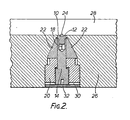
- a 2A type diamond 10 is metallised and pressed into the end of a cylindrical stud 12 made of gold, silver or copper until the surface of the diamond is substantially flush with the end face of the stud 12.
- the stud is held in the end of a holder 14 which has a screw thread 16 at one end and a hollow cylindrical portion at the other end which has two opposed grooves 18 formed in it.
- the walls of the cylindrical portion having the grooves 18 are therefore resilient and can be squeezed inwardly to tightly grip the stud 12.
- the holder 14 is screw threadedly mounted in a lock nut 20 which is adapted to be screwed into a threaded hole formed in a base or wall.
- the hole has a conical portion into which two frustro-conical collets 22 are first fitted.
- the stud 12, holder 14 and locknut 20 are inserted into the hole between the two collets 22.
- the lock nut 20 is screwed into the base or wall causing the stud 12, holder 14 and the collets 22 to move further inside the hole.
- the collets 22 move towards each other squeezing the holder to grip the stud 12.
- the heatsink is shown assembled with a microwave semiconductor device 24 mounted on the diamond 10.
- the heatsink assembly is mounted in a base 26 on which is located a waveguide 28.
- the diameter of the diamond 10 is greater than that of the device 24 to allow the heat from the device to spread in a more or less conical flow pattern, the device being mounted substantially centrally on the diamond.
- the collets 22 are loosened, and the holder 14 can be rotated to position the device 24 at any angle within the waveguide 28.
- the locknut and the holder are provided with slots 30 and 32 respectively to permit the insertion of a suitable tool.
- the assembly has very good heatsinking properties due to the mass of heat conductive metal contacting the stud 12 and good electrical contact is obtained by the holder 14 and collets 22. This is important particularly for millimeter wave applications.
- the arrangement is also particularly easy to assemble and the stud 12 can be replaced without replacing any of the threaded parts.
Landscapes
- Cooling Or The Like Of Semiconductors Or Solid State Devices (AREA)
- Physical Vapour Deposition (AREA)
Claims (9)
Applications Claiming Priority (2)
| Application Number | Priority Date | Filing Date | Title |
|---|---|---|---|
| GB8325320 | 1983-09-21 | ||
| GB838325320A GB8325320D0 (en) | 1983-09-21 | 1983-09-21 | Diamond heatsink assemblies |
Publications (2)
| Publication Number | Publication Date |
|---|---|
| EP0140554A1 EP0140554A1 (fr) | 1985-05-08 |
| EP0140554B1 true EP0140554B1 (fr) | 1988-11-23 |
Family
ID=10549116
Family Applications (1)
| Application Number | Title | Priority Date | Filing Date |
|---|---|---|---|
| EP84306222A Expired EP0140554B1 (fr) | 1983-09-21 | 1984-09-12 | Assemblages contenant un puits de chaleur à diamant |
Country Status (4)
| Country | Link |
|---|---|
| US (1) | US4576224A (fr) |
| EP (1) | EP0140554B1 (fr) |
| DE (1) | DE3475365D1 (fr) |
| GB (2) | GB8325320D0 (fr) |
Families Citing this family (18)
| Publication number | Priority date | Publication date | Assignee | Title |
|---|---|---|---|---|
| US4649992A (en) * | 1984-10-05 | 1987-03-17 | Plessey Overseas Limited | Diamond heatsink assemblies |
| GB2182200B (en) * | 1985-08-31 | 1989-04-26 | Plessey Co Plc | Mesa semiconductor device |
| US5313094A (en) * | 1992-01-28 | 1994-05-17 | International Business Machines Corportion | Thermal dissipation of integrated circuits using diamond paths |
| US5313099A (en) * | 1993-03-04 | 1994-05-17 | Square Head, Inc. | Heat sink assembly for solid state devices |
| US5396404A (en) * | 1993-09-20 | 1995-03-07 | Delco Electronics Corp. | Heat sinking assembly for electrical components |
| US5504653A (en) * | 1994-11-21 | 1996-04-02 | Delco Electronics Corp. | Heat sinking assembly for electrical components |
| US5652696A (en) * | 1995-09-25 | 1997-07-29 | Hughes Aircraft Company | Mechanically captivated integrated circuit chip |
| US6304451B1 (en) | 1999-12-01 | 2001-10-16 | Tyco Electronics Logistics Ag | Reverse mount heat sink assembly |
| US6293331B1 (en) | 2000-08-11 | 2001-09-25 | Tyco Electronics Logistics Ag | Vibration and shock resistant heat sink assembly |
| US6343012B1 (en) | 2000-11-13 | 2002-01-29 | Tyco Electronics Logistis Ag | Heat dissipation device with threaded fan module |
| JP2006511098A (ja) | 2002-10-11 | 2006-03-30 | チエン−ミン・ソン | 炭素質熱スプレッダー及び関連する方法 |
| US20050189647A1 (en) * | 2002-10-11 | 2005-09-01 | Chien-Min Sung | Carbonaceous composite heat spreader and associated methods |
| US20060113546A1 (en) * | 2002-10-11 | 2006-06-01 | Chien-Min Sung | Diamond composite heat spreaders having low thermal mismatch stress and associated methods |
| US7173334B2 (en) | 2002-10-11 | 2007-02-06 | Chien-Min Sung | Diamond composite heat spreader and associated methods |
| US7791188B2 (en) | 2007-06-18 | 2010-09-07 | Chien-Min Sung | Heat spreader having single layer of diamond particles and associated methods |
| US9006086B2 (en) | 2010-09-21 | 2015-04-14 | Chien-Min Sung | Stress regulated semiconductor devices and associated methods |
| US8778784B2 (en) | 2010-09-21 | 2014-07-15 | Ritedia Corporation | Stress regulated semiconductor devices and associated methods |
| CN103221180A (zh) | 2010-09-21 | 2013-07-24 | 铼钻科技股份有限公司 | 具有基本平坦颗粒尖端的超研磨工具及其相关方法 |
Family Cites Families (17)
| Publication number | Priority date | Publication date | Assignee | Title |
|---|---|---|---|---|
| US2233660A (en) * | 1940-04-24 | 1941-03-04 | United Aircraft Corp | Spark plug |
| GB767963A (en) * | 1953-02-16 | 1957-02-13 | Standard Telephones Cables Ltd | Thermionic vacuum tube holder |
| GB887568A (en) * | 1958-06-06 | 1962-01-17 | Gen Electric Co Ltd | Improvements in or relating to mounting arrangements for semiconductor devices |
| CH440464A (de) * | 1966-07-14 | 1967-07-31 | Bbc Brown Boveri & Cie | Kühlkörper für Halbleiterelemente |
| DE1283404B (de) * | 1967-02-16 | 1968-11-21 | Philips Patentverwertung Gmbh | Kuehlkoerperanordnung zur Kontaktkuehlung fuer elektrische Entladungsroehren |
| US3495131A (en) * | 1968-07-16 | 1970-02-10 | Nat Connector Corp | Integrated circuit connector assembly |
| NL6903862A (fr) * | 1969-03-13 | 1970-09-15 | ||
| US3678995A (en) * | 1970-06-22 | 1972-07-25 | Rca Corp | Support for electrical components and method of making the same |
| IL39936A (en) * | 1971-07-30 | 1975-04-25 | De Beers Ind Diamond | A diamond particle particularly for use in heat sinks |
| US3744560A (en) * | 1971-10-01 | 1973-07-10 | Isotopes Inc | Thermal block |
| US3908188A (en) * | 1974-08-14 | 1975-09-23 | Us Air Force | Heat sink for microstrip circuit |
| US3949263A (en) * | 1974-12-20 | 1976-04-06 | Raytheon Company | Diamond brazing method for slow wave energy propagating structures |
| US3972012A (en) * | 1974-12-23 | 1976-07-27 | Rca Corporation | Apparatus for mounting a diode in a microwave circuit |
| US4167031A (en) * | 1978-06-21 | 1979-09-04 | Bell Telephone Laboratories, Incorporated | Heat dissipating assembly for semiconductor devices |
| US4420767A (en) * | 1978-11-09 | 1983-12-13 | Zilog, Inc. | Thermally balanced leadless microelectronic circuit chip carrier |
| US4232277A (en) * | 1979-03-09 | 1980-11-04 | The United States Of America As Represented By The Secretary Of The Army | Microwave oscillator for microwave integrated circuit applications |
| JPS5783082A (en) * | 1980-11-11 | 1982-05-24 | Nippon Telegr & Teleph Corp <Ntt> | Two wave length semiconductor laser device |
-
1983
- 1983-09-21 GB GB838325320A patent/GB8325320D0/en active Pending
-
1984
- 1984-09-12 GB GB08423018A patent/GB2147145B/en not_active Expired
- 1984-09-12 DE DE8484306222T patent/DE3475365D1/de not_active Expired
- 1984-09-12 EP EP84306222A patent/EP0140554B1/fr not_active Expired
- 1984-09-17 US US06/651,466 patent/US4576224A/en not_active Expired - Fee Related
Also Published As
| Publication number | Publication date |
|---|---|
| US4576224A (en) | 1986-03-18 |
| GB2147145B (en) | 1988-11-16 |
| EP0140554A1 (fr) | 1985-05-08 |
| GB8325320D0 (en) | 1983-10-26 |
| DE3475365D1 (en) | 1988-12-29 |
| GB8423018D0 (en) | 1984-10-17 |
| GB2147145A (en) | 1985-05-01 |
Similar Documents
| Publication | Publication Date | Title |
|---|---|---|
| EP0140554B1 (fr) | Assemblages contenant un puits de chaleur à diamant | |
| US4948374A (en) | Assembly for electrically connecting conductive paths of a first body to conductive paths of a second body | |
| US5373099A (en) | Fixing device for fixing electronic component against a wall of a heatsink | |
| US4907989A (en) | Terminal block insert device screw | |
| US6068051A (en) | Channeled heat sink | |
| US6025571A (en) | Nozzle assembly for laser cutting head | |
| US5691509A (en) | Flexible cable termination and connector system | |
| US4768963A (en) | Ground adapter | |
| US4874318A (en) | Mounting arangement for a chip carrier | |
| US5934947A (en) | Battery connector | |
| US5841340A (en) | Solderless RF power film resistors and terminations | |
| KR940004124Y1 (ko) | 인쇄회로기판의 모서리 록킹장치 | |
| US4415218A (en) | Spring loaded diode contact apparatus | |
| EP0153591B1 (fr) | Connexion à vis d'une broche d'une fiche avec un fil conducteur | |
| US5525064A (en) | Connector with molded stud(s) and insulated nuts | |
| US3078438A (en) | Single or strip connectors | |
| JP2000312421A (ja) | 止め具 | |
| US4834671A (en) | Device for connecting electrical cables | |
| US2997688A (en) | Connector | |
| JP3048057B2 (ja) | 電熱線の接続装置 | |
| US4986212A (en) | Metallizing apparatus | |
| US4509808A (en) | High voltage, gas tight connector | |
| JPH0239601A (ja) | マイクロ波ストリップ線コネクター | |
| EP0242005B1 (fr) | Assemblage pour le montage de modules électroniques | |
| US4616896A (en) | Connecting terminal for printed circuit board |
Legal Events
| Date | Code | Title | Description |
|---|---|---|---|
| PUAI | Public reference made under article 153(3) epc to a published international application that has entered the european phase |
Free format text: ORIGINAL CODE: 0009012 |
|
| AK | Designated contracting states |
Designated state(s): DE FR IT NL |
|
| 17P | Request for examination filed |
Effective date: 19851018 |
|
| 17Q | First examination report despatched |
Effective date: 19870128 |
|
| GRAA | (expected) grant |
Free format text: ORIGINAL CODE: 0009210 |
|
| AK | Designated contracting states |
Kind code of ref document: B1 Designated state(s): DE FR IT NL |
|
| ITF | It: translation for a ep patent filed | ||
| REF | Corresponds to: |
Ref document number: 3475365 Country of ref document: DE Date of ref document: 19881229 |
|
| ET | Fr: translation filed | ||
| PLBE | No opposition filed within time limit |
Free format text: ORIGINAL CODE: 0009261 |
|
| STAA | Information on the status of an ep patent application or granted ep patent |
Free format text: STATUS: NO OPPOSITION FILED WITHIN TIME LIMIT |
|
| 26N | No opposition filed | ||
| PGFP | Annual fee paid to national office [announced via postgrant information from national office to epo] |
Ref country code: FR Payment date: 19900919 Year of fee payment: 7 |
|
| ITTA | It: last paid annual fee | ||
| PGFP | Annual fee paid to national office [announced via postgrant information from national office to epo] |
Ref country code: NL Payment date: 19900930 Year of fee payment: 7 |
|
| PGFP | Annual fee paid to national office [announced via postgrant information from national office to epo] |
Ref country code: DE Payment date: 19901031 Year of fee payment: 7 |
|
| PG25 | Lapsed in a contracting state [announced via postgrant information from national office to epo] |
Ref country code: NL Effective date: 19920401 |
|
| NLV4 | Nl: lapsed or anulled due to non-payment of the annual fee | ||
| PG25 | Lapsed in a contracting state [announced via postgrant information from national office to epo] |
Ref country code: FR Effective date: 19920529 |
|
| PG25 | Lapsed in a contracting state [announced via postgrant information from national office to epo] |
Ref country code: DE Effective date: 19920602 |
|
| REG | Reference to a national code |
Ref country code: FR Ref legal event code: ST |