EP0140481A2 - Convecteur ou appareil de chauffage pour un local, par convection/radiation au gaz - Google Patents
Convecteur ou appareil de chauffage pour un local, par convection/radiation au gaz Download PDFInfo
- Publication number
- EP0140481A2 EP0140481A2 EP84304916A EP84304916A EP0140481A2 EP 0140481 A2 EP0140481 A2 EP 0140481A2 EP 84304916 A EP84304916 A EP 84304916A EP 84304916 A EP84304916 A EP 84304916A EP 0140481 A2 EP0140481 A2 EP 0140481A2
- Authority
- EP
- European Patent Office
- Prior art keywords
- heat exchanger
- combustion chamber
- convector
- burner
- combustion
- Prior art date
- Legal status (The legal status is an assumption and is not a legal conclusion. Google has not performed a legal analysis and makes no representation as to the accuracy of the status listed.)
- Withdrawn
Links
Images

Classifications
-
- F—MECHANICAL ENGINEERING; LIGHTING; HEATING; WEAPONS; BLASTING
- F24—HEATING; RANGES; VENTILATING
- F24H—FLUID HEATERS, e.g. WATER OR AIR HEATERS, HAVING HEAT-GENERATING MEANS, e.g. HEAT PUMPS, IN GENERAL
- F24H1/00—Water heaters, e.g. boilers, continuous-flow heaters or water-storage heaters
- F24H1/22—Water heaters other than continuous-flow or water-storage heaters, e.g. water heaters for central heating
- F24H1/24—Water heaters other than continuous-flow or water-storage heaters, e.g. water heaters for central heating with water mantle surrounding the combustion chamber or chambers
- F24H1/26—Water heaters other than continuous-flow or water-storage heaters, e.g. water heaters for central heating with water mantle surrounding the combustion chamber or chambers the water mantle forming an integral body
-
- F—MECHANICAL ENGINEERING; LIGHTING; HEATING; WEAPONS; BLASTING
- F24—HEATING; RANGES; VENTILATING
- F24C—DOMESTIC STOVES OR RANGES ; DETAILS OF DOMESTIC STOVES OR RANGES, OF GENERAL APPLICATION
- F24C1/00—Stoves or ranges in which the fuel or energy supply is not restricted to solid fuel or to a type covered by a single one of the following groups F24C3/00 - F24C9/00; Stoves or ranges in which the type of fuel or energy supply is not specified
- F24C1/14—Radiation heating stoves and ranges, with additional provision for convection heating
-
- F—MECHANICAL ENGINEERING; LIGHTING; HEATING; WEAPONS; BLASTING
- F24—HEATING; RANGES; VENTILATING
- F24C—DOMESTIC STOVES OR RANGES ; DETAILS OF DOMESTIC STOVES OR RANGES, OF GENERAL APPLICATION
- F24C15/00—Details
- F24C15/001—Details arrangements for discharging combustion gases
-
- F—MECHANICAL ENGINEERING; LIGHTING; HEATING; WEAPONS; BLASTING
- F24—HEATING; RANGES; VENTILATING
- F24C—DOMESTIC STOVES OR RANGES ; DETAILS OF DOMESTIC STOVES OR RANGES, OF GENERAL APPLICATION
- F24C3/00—Stoves or ranges for gaseous fuels
- F24C3/002—Stoves
- F24C3/004—Stoves of the closed type
-
- F—MECHANICAL ENGINEERING; LIGHTING; HEATING; WEAPONS; BLASTING
- F24—HEATING; RANGES; VENTILATING
- F24H—FLUID HEATERS, e.g. WATER OR AIR HEATERS, HAVING HEAT-GENERATING MEANS, e.g. HEAT PUMPS, IN GENERAL
- F24H3/00—Air heaters
- F24H3/02—Air heaters with forced circulation
- F24H3/06—Air heaters with forced circulation the air being kept separate from the heating medium, e.g. using forced circulation of air over radiators
- F24H3/065—Air heaters with forced circulation the air being kept separate from the heating medium, e.g. using forced circulation of air over radiators using fluid fuel
-
- F—MECHANICAL ENGINEERING; LIGHTING; HEATING; WEAPONS; BLASTING
- F24—HEATING; RANGES; VENTILATING
- F24H—FLUID HEATERS, e.g. WATER OR AIR HEATERS, HAVING HEAT-GENERATING MEANS, e.g. HEAT PUMPS, IN GENERAL
- F24H8/00—Fluid heaters characterised by means for extracting latent heat from flue gases by means of condensation
-
- F—MECHANICAL ENGINEERING; LIGHTING; HEATING; WEAPONS; BLASTING
- F28—HEAT EXCHANGE IN GENERAL
- F28D—HEAT-EXCHANGE APPARATUS, NOT PROVIDED FOR IN ANOTHER SUBCLASS, IN WHICH THE HEAT-EXCHANGE MEDIA DO NOT COME INTO DIRECT CONTACT
- F28D1/00—Heat-exchange apparatus having stationary conduit assemblies for one heat-exchange medium only, the media being in contact with different sides of the conduit wall, in which the other heat-exchange medium is a large body of fluid, e.g. domestic or motor car radiators
- F28D1/02—Heat-exchange apparatus having stationary conduit assemblies for one heat-exchange medium only, the media being in contact with different sides of the conduit wall, in which the other heat-exchange medium is a large body of fluid, e.g. domestic or motor car radiators with heat-exchange conduits immersed in the body of fluid
- F28D1/0233—Heat-exchange apparatus having stationary conduit assemblies for one heat-exchange medium only, the media being in contact with different sides of the conduit wall, in which the other heat-exchange medium is a large body of fluid, e.g. domestic or motor car radiators with heat-exchange conduits immersed in the body of fluid with air flow channels
- F28D1/024—Heat-exchange apparatus having stationary conduit assemblies for one heat-exchange medium only, the media being in contact with different sides of the conduit wall, in which the other heat-exchange medium is a large body of fluid, e.g. domestic or motor car radiators with heat-exchange conduits immersed in the body of fluid with air flow channels with an air driving element
-
- F—MECHANICAL ENGINEERING; LIGHTING; HEATING; WEAPONS; BLASTING
- F28—HEAT EXCHANGE IN GENERAL
- F28D—HEAT-EXCHANGE APPARATUS, NOT PROVIDED FOR IN ANOTHER SUBCLASS, IN WHICH THE HEAT-EXCHANGE MEDIA DO NOT COME INTO DIRECT CONTACT
- F28D21/00—Heat-exchange apparatus not covered by any of the groups F28D1/00 - F28D20/00
- F28D2021/0019—Other heat exchangers for particular applications; Heat exchange systems not otherwise provided for
- F28D2021/0035—Other heat exchangers for particular applications; Heat exchange systems not otherwise provided for for domestic or space heating, e.g. heating radiators
-
- Y—GENERAL TAGGING OF NEW TECHNOLOGICAL DEVELOPMENTS; GENERAL TAGGING OF CROSS-SECTIONAL TECHNOLOGIES SPANNING OVER SEVERAL SECTIONS OF THE IPC; TECHNICAL SUBJECTS COVERED BY FORMER USPC CROSS-REFERENCE ART COLLECTIONS [XRACs] AND DIGESTS
- Y02—TECHNOLOGIES OR APPLICATIONS FOR MITIGATION OR ADAPTATION AGAINST CLIMATE CHANGE
- Y02B—CLIMATE CHANGE MITIGATION TECHNOLOGIES RELATED TO BUILDINGS, e.g. HOUSING, HOUSE APPLIANCES OR RELATED END-USER APPLICATIONS
- Y02B30/00—Energy efficient heating, ventilation or air conditioning [HVAC]
Definitions
- This invention relates to convector or convector/radiant room heating appliances of the kind in which a gas burner is used to heat the surfaces of a heat exchanger, the heat energy therefrom being transferred to the room to be heated either indirectly by convective hot air currents or directly by radiation, and in some cases by both.
- the heat exchanger may be in the form of purposely designed metal surfaces or a shaped metal box into which the burner products are directed.
- the convected air currents can also be assisted by a ventilation fan to increase air circulation.
- the waste products of the burner gases are discharged outside the building through a flue which is usually a brick chimney, pre-cast flue blocks, asbestos piping or balanced flue terminal. With such flues the only force available for overcoming the resistance to flow of the gases is the natural 'pull' or boyancy force generated by the chimney. In the case of a balanced flue this force is even less.
- heat exchangers have hitherto been designed to give minimum flow resistance so as to prevent exhaust product gas spillage into the room in the case of an open front radiant gas fire, and to prevent poor combustion in a room-sealed heater.
- thermal efficiency of a gas-fired sealed heater is not more than 75X, and only around 55X for an open front gas fire, the corresponding flue gas temperature being between 150°C and 300°C which is a serious waste of heat potential when viewed in the light of world demand for energy conservation.
- a known gas-fired convector/radiant room heating appliance which does not overcome the aforesaid disadvantages, comprises a gas burner, a combustion chamber into which combustion products from the burner are directed, a heat exchanger located adjacent to but spaced from the combustion chamber and over whose surfaces ambient air can flow, a passageway connecting the heat exchanger with the combustion chamber for the flow of combustion products from the top of the chamber to the top of the heat exchanger, and a flue outlet connected to the bottom of the heat exchanger through which waste combustion product gases can be discharged.
- An object of the present invention is to provide a compact, more efficient appliance of this kind which can be positioned almost anywhere in a room having an outside wall.
- the combustion chamber and the heat exchanger are sealed inter-communicating box-like units, the gas burner is contained within the sealed combustion chamber, combustion air for the gas burner is provided by a high pressure air blower, a convector fan is provided beneath the heat exchanger for producing air flow over the surfaces of at least the heat exchanger, and the flue outlet is provided by a length of small bore pipe through which the waste product gases and resultant product condensate liquid are forceably discharged therealong in a substantially horizontal direction by the draught generated by said air blower to a terminal outlet means connected to the small bore flue pipe and located outside the building in which the room is situated, the whole arrangement being such that the thermal efficiency of the appliance is at least 90% of the potential heat source available at the burner, and that the temperature of the waste product gases leaving the heat exchanger is below the dew point and at less than 50°C.
- the appliance shown in Figure 1 is that defined in the pre-characterising part of Claim 1 and comprises a combustion chamber 1 open at its base and front and into which a burner 2 fires onto ceramic radiant elements 3.
- the hot combustion gases pass through a pipe 4 at the top of the combustion chamber 1 into and through a heat exchanger 5 and are thence exhausted through a flue outlet 6 communicating with a chimney.
- ambient air in the room is both radiantly heated and heated by naturally convected currents of air passing through apertures 8 in the base of the appliance casing 9, over the heated surfaces of the heat exchanger and combustion chamber and out through apertures 10 in the top of the casing.
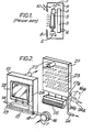
- the appliance comprises, a casing 11 housing a sealed box-like metal combustion chamber 12 containing an aerated gas burner 13 fed from a gas supply 14 and a wire mesh air distribution tube 15 located beneath the burner for distributing air for combustion to the burner, a high performance toroidal air blower 16 which delivers combustion air from an inlet 17 to the distribution tube 15 via an outlet 18 and flexible coupling 19, a heat exchanger 21 communicating with the combustion chamber 12 via a pipe 22 near the top thereof and having a plurality of baffle plates 23 arranged in staggered formation for causing the hot gases to take a tortuous path therethrough before passing into a flue pipe 24 formed of a small bore plastic tube, and a centrifugal fan 25 positioned beneath the heat exchanger 21 for circulating ambient air over the surfaces of the heat exchanger and possibly also the surfaces of the combustion chamber.
- the casing 11 is provided with air entry and exit apertures 26, 27 ( Figures 4 and 5) to and from the casing interior both for the fan-assisted convected
- the sealed combustion chamber 12 in the embodiment shown in Figure 4 serves also as a heat transmitter for circulating ambient air currents and is therefore a pure convector room heater.
- the front part of the combustion chamber 12 is provided with a sealed transparent panel 28 through which radiant heat is transmitted from a ceramic radiant element 29 supported above the burner 13 within the chamber 12.
- the appliance will function as a convector/radiant room heater.
- the appliance describe thus far with reference to the drawings where the toroidal blower 16 is positioned upstream of the chamber and heat exchanger is known as a forced draught heater.
- cold air is sucked into the blower through its inlet 17 and is delivered at about 4m 3 /hour and 5mb of static head pressure to the distribution tube 15.
- the entire heater system is pressurised as it is downstream of the blower and therefore care must be exercised in ensuring that the component parts of the system are adequately sealed to prevent any leakage of flue gases.
- the toroidal air blower 16a can be positioned downstream of the heat exchanger 21 (as shown in chain-dotted lines in Figure 1) so that the air for combustion and the combustion product gases are sucked through the heating system into the blower via an inlet 17a and discharged therefrom to the small bore flue pipe 24a.
- an additional pipe 24b connecting the heat exchanger with the pipe 24a may be provided for directing condensate liquid product from the heat exchanger to be swept along with the forced flow of flue gases along the flue pipe 24a.
- Other kinds of air blowers could be used but suffer the disadvantages of having much larger physical sizes and higher noise levels.
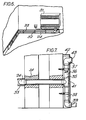
- this shows the heater 31 mounted on a suitable wall of the room with its small bore plastics flue pipe 24 fastened by clips 32 inside a simulated skirting board 33 along the walls. At least 7 meters in length and eight 90 0 bends of the flue pipe can be accommodated in the installation.
- the flue pipe passes through a convenient external wall 34 and is coupled by a T-piece 35 to a flue terminal outlet means comprising an upper vertical plastics tube 36 terminating in an elbow piece 37 for the discharge of flue gases and a lower vertical plastic tube 38 terminating in an elbow piece 39 for draining the condensate product liquid.
- the T-piece 35 is provided with an overflow hole 41 as a safeguard against the possible blockage of the drain tube 39.
- the upper and lower tubes 36, 38 are covered by a plastics trunking 42 and the elbow outlet 37 is protected by a guard 43.
- the appliance will be provided with well known controls and fail-safe mechanisms such as for example (see Figure 3) a burner flame sensor 44, a differential pressure switch 45, a flue gas limit stat 46, an air flow limit stat 47, a full sequential safety check controller 48, a double-acting solenoid gas valve 49, and a gas pressure regulator 50.
- controls and fail-safe mechanisms such as for example (see Figure 3) a burner flame sensor 44, a differential pressure switch 45, a flue gas limit stat 46, an air flow limit stat 47, a full sequential safety check controller 48, a double-acting solenoid gas valve 49, and a gas pressure regulator 50.
Landscapes
- Engineering & Computer Science (AREA)
- Mechanical Engineering (AREA)
- General Engineering & Computer Science (AREA)
- Chemical & Material Sciences (AREA)
- Combustion & Propulsion (AREA)
- Physics & Mathematics (AREA)
- Thermal Sciences (AREA)
- Central Heating Systems (AREA)
- Housings, Intake/Discharge, And Installation Of Fluid Heaters (AREA)
- Air Supply (AREA)
Applications Claiming Priority (2)
| Application Number | Priority Date | Filing Date | Title |
|---|---|---|---|
| GB08329152A GB2149087B (en) | 1983-11-01 | 1983-11-01 | Gas-fired convector |
| GB8329152 | 1983-11-01 |
Publications (2)
| Publication Number | Publication Date |
|---|---|
| EP0140481A2 true EP0140481A2 (fr) | 1985-05-08 |
| EP0140481A3 EP0140481A3 (en) | 1987-04-08 |
Family
ID=10551048
Family Applications (1)
| Application Number | Title | Priority Date | Filing Date |
|---|---|---|---|
| EP84304916A Withdrawn EP0140481A3 (en) | 1983-11-01 | 1984-07-19 | A gas-fired convector or convector/radiant room heating appliance |
Country Status (6)
| Country | Link |
|---|---|
| US (1) | US4531508A (fr) |
| EP (1) | EP0140481A3 (fr) |
| JP (2) | JPS60103247A (fr) |
| AU (1) | AU551315B2 (fr) |
| ES (1) | ES8507678A1 (fr) |
| GB (1) | GB2149087B (fr) |
Cited By (3)
| Publication number | Priority date | Publication date | Assignee | Title |
|---|---|---|---|---|
| GB2202622A (en) * | 1987-02-12 | 1988-09-28 | Keith Charles Law | An exhaust flue unit for a gas fire |
| GB2271173A (en) * | 1992-09-30 | 1994-04-06 | Cannon Ind Ltd | Convector space heater for a gas fire flue duct |
| ES2065814A2 (es) * | 1992-06-15 | 1995-02-16 | Farnos Juan Bautista Prades | Estufa a gas. |
Families Citing this family (7)
| Publication number | Priority date | Publication date | Assignee | Title |
|---|---|---|---|---|
| GB2199654B (en) * | 1986-11-25 | 1990-11-14 | Thomas Raymond Collier | Gas fire incorporating its own flue |
| US5230161A (en) * | 1989-03-28 | 1993-07-27 | Haden Schweitzer Corporation | Apparatus and process for generating radiant energy |
| GB2352288A (en) * | 1999-04-21 | 2001-01-24 | Cfm Kinder Ltd | Gas fire |
| US7151264B2 (en) * | 2004-12-21 | 2006-12-19 | Ranco Incorporated Of Delaware | Inline air handler system and associated method of use |
| US7544291B2 (en) * | 2004-12-21 | 2009-06-09 | Ranco Incorporated Of Delaware | Water purification system utilizing a plurality of ultraviolet light emitting diodes |
| US20060199129A1 (en) * | 2005-03-01 | 2006-09-07 | Foremost Groups, Inc. | Decorative torch for use with pressurized fuel source |
| AT516353A3 (de) * | 2014-07-28 | 2017-05-15 | Gehrer Marco | Wärmetauscher |
Citations (5)
| Publication number | Priority date | Publication date | Assignee | Title |
|---|---|---|---|---|
| US2376171A (en) * | 1941-03-22 | 1945-05-15 | Moritz L Mueller | Heating apparatus |
| GB1181651A (en) * | 1966-01-04 | 1970-02-18 | United Gas Industries Ltd | Improvements in or relating to Air Heaters |
| DE1778150A1 (de) * | 1967-04-04 | 1971-07-29 | Gas Council | Gasheizgeraet |
| GB1489337A (en) * | 1974-11-07 | 1977-10-19 | United Gas Industries Ltd | Space heating appliances |
| GB2056650A (en) * | 1979-08-16 | 1981-03-18 | United Gas Industries Ltd | Gas-fired heater |
Family Cites Families (10)
| Publication number | Priority date | Publication date | Assignee | Title |
|---|---|---|---|---|
| US2603208A (en) * | 1952-07-15 | Downdraft hot-air furnace | ||
| US1991513A (en) * | 1931-10-02 | 1935-02-19 | Moore Brothers Co | Stove construction |
| US1942936A (en) * | 1932-04-12 | 1934-01-09 | Reznor Mfg Company | Gas heater |
| GB928676A (en) * | 1961-03-24 | 1963-06-12 | Parkinson Cowan Appliances Ltd | Gas-fired space heater |
| GB1028701A (en) * | 1962-01-22 | 1966-05-04 | United Gas Industries Ltd | Improvements in gas convector fires and the like |
| GB1118781A (en) * | 1964-04-21 | 1968-07-03 | Parkinson Cowan Appliances Ltd | Gas-fired heaters |
| GB1418867A (en) * | 1971-10-25 | 1975-12-24 | Imp Metal Ind Kynoch Ltd | Gas-fired appliance |
| JPS5234556B2 (fr) * | 1972-05-17 | 1977-09-03 | ||
| JPS5316223B2 (fr) * | 1973-04-03 | 1978-05-30 | ||
| JPS5341904A (en) * | 1976-09-29 | 1978-04-15 | Hitachi Ltd | Double polling device |
-
1983
- 1983-11-01 GB GB08329152A patent/GB2149087B/en not_active Expired
-
1984
- 1984-07-19 EP EP84304916A patent/EP0140481A3/en not_active Withdrawn
- 1984-07-24 US US06/633,914 patent/US4531508A/en not_active Expired - Lifetime
- 1984-08-07 JP JP59165550A patent/JPS60103247A/ja active Pending
- 1984-10-25 AU AU34685/84A patent/AU551315B2/en not_active Ceased
- 1984-10-31 ES ES537282A patent/ES8507678A1/es not_active Expired
-
1988
- 1988-11-22 JP JP1988152393U patent/JPH01112361U/ja active Pending
Patent Citations (5)
| Publication number | Priority date | Publication date | Assignee | Title |
|---|---|---|---|---|
| US2376171A (en) * | 1941-03-22 | 1945-05-15 | Moritz L Mueller | Heating apparatus |
| GB1181651A (en) * | 1966-01-04 | 1970-02-18 | United Gas Industries Ltd | Improvements in or relating to Air Heaters |
| DE1778150A1 (de) * | 1967-04-04 | 1971-07-29 | Gas Council | Gasheizgeraet |
| GB1489337A (en) * | 1974-11-07 | 1977-10-19 | United Gas Industries Ltd | Space heating appliances |
| GB2056650A (en) * | 1979-08-16 | 1981-03-18 | United Gas Industries Ltd | Gas-fired heater |
Cited By (5)
| Publication number | Priority date | Publication date | Assignee | Title |
|---|---|---|---|---|
| GB2202622A (en) * | 1987-02-12 | 1988-09-28 | Keith Charles Law | An exhaust flue unit for a gas fire |
| GB2202622B (en) * | 1987-02-12 | 1991-03-13 | Keith Charles Law | An exhaust flue unit for a gas fire |
| ES2065814A2 (es) * | 1992-06-15 | 1995-02-16 | Farnos Juan Bautista Prades | Estufa a gas. |
| GB2271173A (en) * | 1992-09-30 | 1994-04-06 | Cannon Ind Ltd | Convector space heater for a gas fire flue duct |
| GB2271173B (en) * | 1992-09-30 | 1996-07-03 | Cannon Ind Ltd | Gas fire |
Also Published As
| Publication number | Publication date |
|---|---|
| US4531508A (en) | 1985-07-30 |
| EP0140481A3 (en) | 1987-04-08 |
| GB8329152D0 (en) | 1983-12-07 |
| GB2149087A (en) | 1985-06-05 |
| ES537282A0 (es) | 1985-09-16 |
| AU3468584A (en) | 1985-05-09 |
| AU551315B2 (en) | 1986-04-24 |
| JPS60103247A (ja) | 1985-06-07 |
| ES8507678A1 (es) | 1985-09-16 |
| GB2149087B (en) | 1987-09-23 |
| JPH01112361U (fr) | 1989-07-28 |
Similar Documents
| Publication | Publication Date | Title |
|---|---|---|
| US3813039A (en) | Heat exchanger | |
| CA2210191A1 (fr) | Systeme de chauffage | |
| US4531508A (en) | Gas-fired convector or convector/radiant room heating appliance | |
| US4738394A (en) | Integral liquid-backed gas-fired space heating and hot water system | |
| RU2359174C2 (ru) | Печь для бани | |
| US4066210A (en) | Chimney heat reclaimer | |
| US4671212A (en) | Gas fired heat exchanger for hot water with bimetallic scouring baffle | |
| US3274990A (en) | Mass-production low-cost furnace for supplying high-temperature highvelocity air fordomestic heating | |
| US4009705A (en) | Venting system for a gas-fired heating plant | |
| GB2044441A (en) | Water heating arrangements in stoves | |
| US3536048A (en) | Instantaneous hot water heater and hot air supply | |
| GB2330899A (en) | Flue system | |
| CA1055797A (fr) | Systeme d'event pour centrale de chauffage au gaz | |
| US4310746A (en) | Electric fluid heating apparatus | |
| RU96109009A (ru) | Котельная установка | |
| CA2331168C (fr) | Systeme echangeur de chaleur flexible a gaz | |
| US3537431A (en) | Outdoor gas-burning appliance | |
| EP0108453B1 (fr) | Appareil à gaz pour produire de la chaleur pour une maison | |
| US5971292A (en) | Method of venting a furnace | |
| US4337894A (en) | Wall protective heating system | |
| EP0146222B1 (fr) | Système de chauffage | |
| RU2282111C1 (ru) | Устройство для теплосберегающей вентиляции помещения | |
| RU2126942C1 (ru) | Теплогенератор | |
| AU2001100015A4 (en) | Space heater | |
| FR2806466B1 (fr) | Installation de chauffage et de climatisation avec caisson a facade rayonnante |
Legal Events
| Date | Code | Title | Description |
|---|---|---|---|
| PUAI | Public reference made under article 153(3) epc to a published international application that has entered the european phase |
Free format text: ORIGINAL CODE: 0009012 |
|
| AK | Designated contracting states |
Designated state(s): BE DE FR IT NL SE |
|
| 17P | Request for examination filed |
Effective date: 19850603 |
|
| PUAL | Search report despatched |
Free format text: ORIGINAL CODE: 0009013 |
|
| AK | Designated contracting states |
Kind code of ref document: A3 Designated state(s): BE DE FR IT NL SE |
|
| 17Q | First examination report despatched |
Effective date: 19871002 |
|
| STAA | Information on the status of an ep patent application or granted ep patent |
Free format text: STATUS: THE APPLICATION IS DEEMED TO BE WITHDRAWN |
|
| 18D | Application deemed to be withdrawn |
Effective date: 19880825 |
|
| RIN1 | Information on inventor provided before grant (corrected) |
Inventor name: TUNG, MING-BIU Inventor name: NIKNEJAD, JALIL |