EP0139572B1 - Appareil de traitement des eaux par précipitation, séparation, Epaississement et recirculation des des boues formées - Google Patents
Appareil de traitement des eaux par précipitation, séparation, Epaississement et recirculation des des boues formées Download PDFInfo
- Publication number
- EP0139572B1 EP0139572B1 EP84401934A EP84401934A EP0139572B1 EP 0139572 B1 EP0139572 B1 EP 0139572B1 EP 84401934 A EP84401934 A EP 84401934A EP 84401934 A EP84401934 A EP 84401934A EP 0139572 B1 EP0139572 B1 EP 0139572B1
- Authority
- EP
- European Patent Office
- Prior art keywords
- sludge
- chamber
- water
- thickening
- reaction chamber
- Prior art date
- Legal status (The legal status is an assumption and is not a legal conclusion. Google has not performed a legal analysis and makes no representation as to the accuracy of the status listed.)
- Expired
Links
Images

Classifications
-
- C—CHEMISTRY; METALLURGY
- C02—TREATMENT OF WATER, WASTE WATER, SEWAGE, OR SLUDGE
- C02F—TREATMENT OF WATER, WASTE WATER, SEWAGE, OR SLUDGE
- C02F1/00—Treatment of water, waste water, or sewage
- C02F1/52—Treatment of water, waste water, or sewage by flocculation or precipitation of suspended impurities
- C02F1/5281—Installations for water purification using chemical agents
-
- B—PERFORMING OPERATIONS; TRANSPORTING
- B01—PHYSICAL OR CHEMICAL PROCESSES OR APPARATUS IN GENERAL
- B01D—SEPARATION
- B01D21/00—Separation of suspended solid particles from liquids by sedimentation
- B01D21/0039—Settling tanks provided with contact surfaces, e.g. baffles, particles
- B01D21/0051—Plurality of tube like channels
-
- B—PERFORMING OPERATIONS; TRANSPORTING
- B01—PHYSICAL OR CHEMICAL PROCESSES OR APPARATUS IN GENERAL
- B01D—SEPARATION
- B01D21/00—Separation of suspended solid particles from liquids by sedimentation
- B01D21/0039—Settling tanks provided with contact surfaces, e.g. baffles, particles
- B01D21/0057—Settling tanks provided with contact surfaces, e.g. baffles, particles with counter-current flow direction of liquid and solid particles
-
- B—PERFORMING OPERATIONS; TRANSPORTING
- B01—PHYSICAL OR CHEMICAL PROCESSES OR APPARATUS IN GENERAL
- B01D—SEPARATION
- B01D21/00—Separation of suspended solid particles from liquids by sedimentation
- B01D21/02—Settling tanks with single outlets for the separated liquid
- B01D21/04—Settling tanks with single outlets for the separated liquid with moving scrapers
-
- B—PERFORMING OPERATIONS; TRANSPORTING
- B01—PHYSICAL OR CHEMICAL PROCESSES OR APPARATUS IN GENERAL
- B01D—SEPARATION
- B01D21/00—Separation of suspended solid particles from liquids by sedimentation
- B01D21/02—Settling tanks with single outlets for the separated liquid
- B01D21/04—Settling tanks with single outlets for the separated liquid with moving scrapers
- B01D21/06—Settling tanks with single outlets for the separated liquid with moving scrapers with rotating scrapers
-
- B—PERFORMING OPERATIONS; TRANSPORTING
- B01—PHYSICAL OR CHEMICAL PROCESSES OR APPARATUS IN GENERAL
- B01D—SEPARATION
- B01D21/00—Separation of suspended solid particles from liquids by sedimentation
- B01D21/02—Settling tanks with single outlets for the separated liquid
- B01D21/08—Settling tanks with single outlets for the separated liquid provided with flocculating compartments
-
- B—PERFORMING OPERATIONS; TRANSPORTING
- B01—PHYSICAL OR CHEMICAL PROCESSES OR APPARATUS IN GENERAL
- B01D—SEPARATION
- B01D21/00—Separation of suspended solid particles from liquids by sedimentation
- B01D21/24—Feed or discharge mechanisms for settling tanks
- B01D21/2488—Feed or discharge mechanisms for settling tanks bringing about a partial recirculation of the liquid, e.g. for introducing chemical aids
-
- B—PERFORMING OPERATIONS; TRANSPORTING
- B01—PHYSICAL OR CHEMICAL PROCESSES OR APPARATUS IN GENERAL
- B01D—SEPARATION
- B01D21/00—Separation of suspended solid particles from liquids by sedimentation
- B01D21/28—Mechanical auxiliary equipment for acceleration of sedimentation, e.g. by vibrators or the like
- B01D21/286—Means for gentle agitation for enhancing flocculation
Definitions
- the present invention relates to an apparatus for treating water by flocculation and / or crystal precipitation, then by lamellar decantation with separation of the sludges formed by decantation-thickening and recirculation of part of these sludges after their thickening.
- This device applies to the treatment of all kinds of water: surface water loaded with suspended and colloidal matter, waste water and in particular to the treatment of water loaded with precipitable mineral salts in the form of crystalline sludge with a reagent such as lime for example.
- Deepening the device does not solve the problem because the device's performance then remains limited by the maximum possible value of the flow horizontal recirculation, which, to maintain the required concentration of sludge in the flocculation and reaction chamber, must be proportional to the flow of water to be treated and it can be seen that from a certain value of this corresponding recirculation flow at a treatment rate and therefore at a settling speed much lower than that allowed by the presence of the lamellar modules, turbulence is created under these modules causing an unacceptable deterioration in the quality of the treated water.
- the device according to the invention overcomes these drawbacks by allowing operation at a flow rate corresponding to the maximum settling speed allowed by the lamellar modules, by obtaining large and dense flocs or precipitates, high sedimentation speed and the elimination of the horizontal transit of the recirculation flow in the zone located under the lamellar modules.
- the water treatment apparatus comprising in a same enclosure a plurality of chambers, one of which for reaction such as coagulation, flocculation and / or crystal precipitation and another for lamellar decantation, with recirculation of the sludge formed towards the chamber of reaction, is characterized in that, between the reaction chamber and the lamellar settling chamber and in communication with them is interposed an intermediate chamber for thickening the sludge, this chamber being provided with means for recirculation to the reaction chamber , of a part of the sludge before its maximum thickening, together or not with the sludge extracted from the lamellar settling chamber and of means for the extraction of the sludge at the end of thickening.
- the reaction chamber comprises two zones: a central zone constituted by two coaxial, parallelepipedic or cylindrical enclosures, the internal enclosure in which the water to be treated is admitted being equipped with a propeller with essentially axial flow and capable of inducing a flow rate of 2 to 10 times that of the water to be treated so as to ensure internal recirculation between these two enclosures and a peripheral or lateral zone for enlarging and densifying the floc whose concentration is maintained around from 0.5 to 10 g / l, depending on whether it is a flocculation or crystalline precipitation treatment, thanks to the introduction into the raw water of sludge from the intermediate thickening chamber sludge.
- the intermediate sludge thickening chamber has two zones, one upper water transit from the reaction zone to the lamellar settling zone, the other lower thickening, the latter comprising a sludge collector advantageously equipped with a conventional device, such as a harrow and a scraper, allowing to increase the concentration of thickened sludge.
- This intermediate chamber makes it possible to remove 85 to 90% of the particles in suspension in the water leaving the reaction chamber. In addition, it makes it possible to obtain sludges whose concentration at the lowest point of the chamber can reach 80 to 100 g / 1 in the case of a flocculation treatment and 300 to 500 g / 1 in the case of a crystal precipitation treatment.
- the intermediate chamber is provided with means intended for the recirculation of part of the sludge formed in this chamber towards the reaction chamber so as to obtain there an optimal concentration of sludge, said means consisting of at least one piping arranged between the upper half and the third of the height of the thickening zone and connected either to the suction of a recycling pump or to that of an ejector, arranged on the water supply piping crude to the reaction chamber.
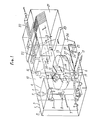
- FIG. 1 represents such a device in cutaway perspective, the dark arrows showing the path of the sludge, the light arrows that of the water, and
- Figure 2 is a section along 11/11 of Figure 1.
- the apparatus comprises a reaction chamber 1 organized so as to present two zones: a central zone 2 and, ruling on either side of this zone, a peripheral or lateral zone 3.
- the central zone 2 consists of two coaxial enclosures, one parallelepiped 4, the other cylindrical 5.
- the water to be treated added with the reagents necessary for the treatment and to which the recycled sludge is mixed, under the conditions which will be seen below.
- An adjuvant, for example polymer is brought into this enclosure by a pipe 7.
- a propeller 8 In the internal cylindrical enclosure is a propeller 8 with axial flow, driven by a group 9.
- This propeller is calculated so as to induce in enclosure 5 a very large flow rate of the liquor, of the order of 2 to 10 times that under which it is introduced into this enclosure. This creates intense recirculation between the two chambers, which ensures intimate contact between the water, the reagents and the sludge introduced at the base of the internal chamber. From the external enclosure, the water-sludge mixture passes into the peripheral zone 3 which constitutes a zone of slow flocculation allowing the formation of large dense flakes which pass into the intermediate chamber 10 through orifices 11 forming overflows, provided at the upper part d 'a partition 12 separating the reaction chamber 1 from the intermediate chamber 10.
- This intermediate chamber 10 is provided with a cylindrical-conical sludge collector 13 equipped with a scraper 14 and a harrow 15 driven by a group 16 and intended to promote the thickening of decanted sludge.
- a pipe 17 provided at the base of the collector 13 is used for the evacuation of thickened sludge.
- a pipe 18 provided at an intermediate height in the chamber 10 is connected to a recirculation device, such as for example a pump 19, interposed on the pipe 6 for supplying the water to be treated to the lower part of the enclosure internal cylindrical 5 of the reaction chamber 1.
- a recirculation device such as for example a pump 19 interposed on the pipe 6 for supplying the water to be treated to the lower part of the enclosure internal cylindrical 5 of the reaction chamber 1.
- This lamellar settling chamber can advantageously include at its lower part a scraper device 23 making it possible to bring the decanted sludge into one or more concentration pits 24, from which thanks to the set of pipes 25 and 26, and valves 27 and 28 which equip them, they can either be evacuated in the sewer, or recycled together with the sludge extracted from the intermediate chamber 10.
Landscapes
- Chemical & Material Sciences (AREA)
- Chemical Kinetics & Catalysis (AREA)
- General Chemical & Material Sciences (AREA)
- Life Sciences & Earth Sciences (AREA)
- Hydrology & Water Resources (AREA)
- Engineering & Computer Science (AREA)
- Environmental & Geological Engineering (AREA)
- Water Supply & Treatment (AREA)
- Organic Chemistry (AREA)
- Separation Of Suspended Particles By Flocculating Agents (AREA)
- Treatment Of Sludge (AREA)
Description
- La présente invention concerne un appareil de traitement des eaux par floculation et/ou précipitation cristalline, puis par décantation lamellaire avec séparation des boues formées par décantation-épaississement et recirculation d'une partie de ces boues après leur épaississement.
- Cet appareil s'applique au traitement de toutes sortes d'eaux : eaux de surface chargées de matières en suspension et colloïdales, eaux résiduaires et en particulier au traitement des eaux chargées en sels minéraux précipitables sous forme de boues cristallines par un réactif tel que la chaux par exemple.
- Dans sa demande de brevet FR-A-2 345 396, la Demanderesse a déjà décrit un appareil de traitement des eaux par recirculation, précipitation et séparation des boues formées, comportant dans une même enceinte deux zones, l'une de réaction telle que coagulation, floculation, précipitation cristalline, l'autre de décantation lamellaire, ces zones étant en communication sur toute la largeur de l'appareil et permettant une recirculation interne d'une partie des boues formées.
- De nombreux autres appareils ont déjà été décrits, par exemple dans la demande de brevet FR-A-2 348156 qui comportent un floculateur et un décanteur lamellaire avec recirculation des boues du décanteur vers le floculateur au moyen d'un hydroéjecteur.
- Cependant, très souvent, le facteur limitant les performances de ces appareils n'est pas la vitesse de décantation mais le volume de boues produit lors du traitement.
- Par tailleurs, leur bon fonctionnement est conditionné par le maintien dans la zone de réaction-floculation d'une concentration correcte en boues amenées par le flux de recirculation et l'obtention d'une telle concentration devient aléatoire au-delà d'un certain débit d'eau traitée correspondant à une vitesse de décantation inférieure à celle théoriquement possible dans la zone de décantation lamellaire.
- En effet, à toute augmentation de la vitesse de décantation, et donc du débit d'eau traitée dans un appareil de dimensions données, correspond un accroissement proportionnel de la production de boues et le volume disponible sous les modules lamellaires pour le stockage de ces boues ne pouvant varier, il s'ensuit une impossibilité, sans risque d'engorgement de l'appareil, de respecter pour elles un temps de séjour suffisant sous les modules lamellaires, de façon à assurer leur épaississement pour en obtenir, d'une part la concentration correcte dans le flux de recirculation et, d'autre part, la concentration maximale possible dans celui extrait.
- L'approfondissement de l'appareil, de façon à aménager sous les modules un volume suffisant pour le stockage et l'épaississement des boues, ne résoud pas le probléme car les performances de l'appareil demeurent alors limitées par la valeur maximale possible du flux horizontal de recirculation, qui, pour maintenir la concentration requise en boues dans la chambre de floculation et de réaction, doit être proportionné au débit d'eau à traiter et on constate qu'à partir d'une certaine valeur de ce flux de recirculation correspondant à un débit de traitement et donc à une vitesse de décantation bien inférieure à celle permise par la présence des modules lamellaires, il se crée sous ces modules des turbulences provoquant une détérioration inacceptable de la qualité de l'eau traitée.
- L'appareil suivant l'invention pallie ces inconvénients en permettant un fonctionnement à un débit correspondant à la vitesse de décantation maximale permise par les modules lamellaires, grâce à l'obtention de flocs ou précipités gros et denses, de vitesse de sédimentation élevée et à la suppression du transit horizontal du débit de recirculation dans la zone située sous les modules lamellaires.
- L'appareil de traitement des eaux suivant l'invention,comportant dans une même enceinte une pluralité de chambres dont une de réaction telle que coagulation, floculation et/ou précipitation cristalline et une autre de décantation lamellaire, avec recirculation des boues formées vers la chambre de réaction , est caractérisé en ce que, entre la chambre de réaction et la chambre de décantation lamellaire et en communication avec elles est intercalée une chambre intermédiaire d'épaississement des boues, cette chambre étant munie de moyens pour la recirculation vers la chambre de réaction, d'une partie des boues avant leur épaississement maximal, conjointement ou non avec les boues extraites de la chambre de décantation lamellaire et de moyens pour l'extraction des boues en fin d'épaississement.
- Conformément à l'invention, la chambre de réaction comporte deux zones: une zone centrale constituée par deux enceintes coaxiales, parallélépipédiques ou cylindriques, l'enceinte interne dans laquelle l'eau à traiter est admise étant équipée d'une hélice à flux essentiellement axial et capable d'induire un débit de 2 à 10 fois celui de l'eau à traiter de manière à assurer une recirculation interne entre ces deux enceintes et une zone péripherique ou latérale de grossissement et de densification du floc dont la concentration est maintenue aux environs de 0,5 à 10 g/l, selon qu'il s'agit d'un traitement de floculation ou de précipitation cristalline, grâce à l'introduction dans l'eau brute de boues en provenance de la chambre intermédiaire d'épaississement des boues.
- Egalement suivant l'invention, la chambre intermédiaire d'épaississement des boues présente deux zones, l'une supérieure de transit de l'eau de la zone de réaction vers la zone de décantation lamellaire, l'autre inférieure d'épaississement, cette dernière comportant un collecteur de boues avantageusement équipé d'un dispositif classique, tel que herse et râcleur, permettant d'accroître la concentration des boues épaissies.
- Cette chambre intermédiaire permet d'éliminer 85 à 90 % des particules en suspension dans l'eau sortant de la chambre de réaction. En outre, elle permet d'obtenir des boues dont la concentration au point le plus bas de la chambre peut atteindre 80 à 100 g/1 dans le cas d'un traitement de floculation et 300 à 500 g/1 dans le cas d'un traitement de précipitation cristalline.
- Conformément à l'invention, la chambre intermédiaire est munie de moyens destinés à la recirculation d'une partie des boues formées dans cette chambre vers la chambre de réaction de façon à y obtenir une concentration optimale des boues, lesdits moyens consistant en au moins une tuyauterie disposée entre la moitié et le tiers supérieur de la hauteur de la zone d'épaississement et reliée soit à l'aspiration d'une pompe de recyclage, soit à celle d'un éjecteur, disposés sur la tuyauterie d'amenée d'eau brute à la chambre de réaction.
- On a décrit ci-après, uniquement à titre d'exemple non limitatif, une forme de réalisation d'un appareil suivant l'invention, cette description étant faite en référence aux dessins annexés sur lesquels:
- la figure 1 représente un tel appareil en perspective arrachée, les flèches sombres montrant le trajet des boues, les flèches claires celui de l'eau, et
- la figure 2 est une coupe suivant 11/11 de la figure 1.
- L'appareil comporte une chambre de réaction 1 organisée de façon à présenter deux zones: une zone centrale 2 et, régnant de part et d'autre de cette zone, une zone périphérique ou latérale 3. Dans l'exemple traité, la zone centrale 2 est constituée par deux enceintes coaxiales l'une parallélépipédique 4, l'autre cylindrique 5. L'eau à traiter, additionnée des réactifs nécessaires au traitement et à laquelle sont mélangées les boues recyclées, dans les conditions que l'on verra plus loin, est introduite par la canalisation 6 à la base de l'enceinte interne cylindrique 5. Un adjuvant, polymère par exemple, est amené dans cette enceinte par une tuyauterie 7. Dans l'enceinte cylindrique interne est disposée une hélice 8 à flux axial, entrainée par un groupe 9. Cette hélice est calculée de façon à induire dans l'enceinte 5 un débit très important de la liqueur, de l'ordre de 2 à 10 fois celui sous lequel elle est introduite dans cette enceinte. Il se crée ainsi une recirculation intense entre les deux enceintes, ce qui assure un contact intime entre l'eau, les réactifs et les boues introduites à la base de l'enceinte interne. De l'enceinte extérieure le mélange eau-boues passe dans la zone périphérique 3 qui constitue une zone de floculation lente permettant la formation de gros flocons denses qui passent dans la chambre intermédiaire 10 par des orifices 11 formant déversoirs, prévus à la partie supérieure d'un cloisonnement 12 séparant la chambre de réaction 1 de la chambre intermédiaire 10. Cette chambre intermédiaire 10 est munie d'un collecteur de boues 13 cylindro-conique équipé d'un ràcleur 14 et d'une herse 15 entraînés par un groupe 16 et destinés à favoriser l'épaississement des boues décantées. Une tuyauterie 17 prévue à la base du collecteur 13 sert à l'évacuation des boues épaissies.
- Une tuyauterie 18 prévue à une hauteur intermédiaire dans la chambre 10 est reliée à un dispositif de recirculation, tel que par exemple une pompe 19, interposée sur la canalisation 6 d'amenée de l'eau à traiter à la partie inférieure de l'enceinte cylindrique interne 5 de la chambre de réaction 1. L'eau sortant de la chambre 10, dont la teneur en matières en suspension est, grâce aux dispositions adoptées suivant l'invention, réduite de 85 à 90 %, pénètre par l'orifice 20 dans la chambre de décantation lamellaire 21 où a lieu le finissage de la décantation et à la partie supérieure de laquelle l'eau est reprise par les goulottes 22.
- Cette chambre de décantation lamellaire peut avantageusement comporter à sa partie inférieure un dispositif de râclage 23 permettant de ramener les boues décantées dans une ou plusieurs fosses de concentration 24, à partir desquelles grâce au jeu de tuyauteries 25 et 26, et des vannes 27 et 28 qui les équipent, elles peuvent être soit évacuées à l'égoût, soit recyclées conjointement avec les boues extraites de la chambre intermédiaire 10.
- Des mesures comparatives ont été faites sur deux appareils ayant une surface de décantation lamellaire identique et traitant en parallèle une même eau (eau de surface), par addition d'une même dose de réactif minéral coagulant et de polymère. L'un de ces appareils (n° 1) comportait une recirculation classique interne des boues, l'autre (n° 2) était conforme à la présente invention.
- Les résultats suivants ont été obtenus:
- Appareil n° 1 Appareil n° 2
- - Vistesse de décantation dans la zone lamellaire 17 m/h 35 m/h
- - Teneur moyenne en matières en suspension de l'eau traitée 4 mg/l 3,6 mg/1
- - Concentration moyenne des boues extraites 19 g/l 60 g/1
Claims (7)
Applications Claiming Priority (2)
| Application Number | Priority Date | Filing Date | Title |
|---|---|---|---|
| FR8315977A FR2553082B1 (fr) | 1983-10-07 | 1983-10-07 | Appareil de traitement des eaux par precipitation, separation, epaississement et recirculation des boues formees |
| FR8315977 | 1983-10-07 |
Publications (2)
| Publication Number | Publication Date |
|---|---|
| EP0139572A1 EP0139572A1 (fr) | 1985-05-02 |
| EP0139572B1 true EP0139572B1 (fr) | 1986-11-26 |
Family
ID=9292922
Family Applications (1)
| Application Number | Title | Priority Date | Filing Date |
|---|---|---|---|
| EP84401934A Expired EP0139572B1 (fr) | 1983-10-07 | 1984-09-27 | Appareil de traitement des eaux par précipitation, séparation, Epaississement et recirculation des des boues formées |
Country Status (7)
| Country | Link |
|---|---|
| US (1) | US4579655A (fr) |
| EP (1) | EP0139572B1 (fr) |
| JP (1) | JPS6097007A (fr) |
| CA (1) | CA1234434A (fr) |
| DE (2) | DE139572T1 (fr) |
| ES (1) | ES536533A0 (fr) |
| FR (1) | FR2553082B1 (fr) |
Families Citing this family (31)
| Publication number | Priority date | Publication date | Assignee | Title |
|---|---|---|---|---|
| FR2591215B1 (fr) * | 1985-12-11 | 1990-12-07 | Omnium Traitement Valorisa | Ensemble de traitement combine de floculation et decantation des eaux |
| US4818392A (en) * | 1987-11-30 | 1989-04-04 | Hazleton Environmental Products Inc. | Liquid waste treatment system |
| FR2627704B1 (fr) * | 1988-02-25 | 1991-12-13 | Ile France Syndicat Eaux | Procede et installation de traitement d'eau par decantation faisant intervenir du sable fin |
| SE466197B (sv) * | 1988-03-22 | 1992-01-13 | K Z Handels Ab | Foerfarande och anordning vid biologiskt reningssteg av avloppsvatten i luftade bassaenger |
| US5192441A (en) * | 1989-02-14 | 1993-03-09 | Omnium De Traitements Et De Valorisation (Otv) | Process and installation for biological treatment, e.g. by nitrification and/or denitrification, of an effluent including nitrated pollution |
| US5242600A (en) * | 1990-09-04 | 1993-09-07 | Meylor Donald M | Wastewater separation system |
| USD356624S (en) | 1993-03-23 | 1995-03-21 | Wastech | Waste separator |
| FR2719234B1 (fr) * | 1994-05-02 | 1999-08-13 | Omnium Traitement Valorisa | Procédé et installation de traitement d'un écoulement brut par décantation simple après lestage au sable fin. |
| US5800717A (en) * | 1996-10-02 | 1998-09-01 | Microsep International Corporation | Water and wastewater treatment system with internal recirculation |
| JP3769148B2 (ja) * | 1999-07-05 | 2006-04-19 | シャープ株式会社 | 排水処理装置 |
| FR2801878B1 (fr) * | 1999-12-03 | 2002-02-22 | Degremont | Procede et installation de clarification des liquides et suspensions par floculation lestee et decantation |
| FR2810898B1 (fr) * | 2000-06-29 | 2002-09-27 | Amenagement Urbain & Rural | Procede et dispositif de traitement des eaux avec lestant injecte en zone tranquilisee |
| US6383370B1 (en) | 2000-09-14 | 2002-05-07 | Infilco Degremont Inc. | Apparatus for treating wastewater |
| GB2366745B (en) * | 2000-09-14 | 2005-02-02 | David Alan Burt | Glycol/water separator |
| US20030150817A1 (en) * | 2002-02-11 | 2003-08-14 | Keever Christopher S. | Method and apparatus for treating wastewater |
| AUPS217702A0 (en) * | 2002-05-07 | 2002-06-06 | Outokumpu Oyj | Dilution apparatus for a thickener |
| AU2007100006B4 (en) * | 2002-05-07 | 2007-01-25 | Outotec Oyj | Dilution apparatus for a thickener |
| RU2229919C1 (ru) * | 2002-09-25 | 2004-06-10 | Казанцев Владимир Иванович | Аппарат для осветления жидкости |
| US7048852B2 (en) * | 2002-10-31 | 2006-05-23 | Infilco Degremont, Inc. | Method and apparatus for treating water or wastewater to reduce organic and hardness contamination |
| KR100647716B1 (ko) | 2005-02-15 | 2006-11-23 | 한국수자원공사 | 정수처리시설용 일체형 응집 및 침전장치 |
| US20110036771A1 (en) | 2007-01-09 | 2011-02-17 | Steven Woodard | Ballasted anaerobic system and method for treating wastewater |
| US8470172B2 (en) | 2007-01-09 | 2013-06-25 | Siemens Industry, Inc. | System for enhancing a wastewater treatment process |
| US20100213123A1 (en) | 2007-01-09 | 2010-08-26 | Marston Peter G | Ballasted sequencing batch reactor system and method for treating wastewater |
| AU2008205247B2 (en) | 2007-01-09 | 2010-07-01 | Evoqua Water Technologies Llc | A system and method for removing dissolved contaminants, particulate contaminants, and oil contaminants from industrial waste water |
| WO2008086010A1 (fr) | 2007-01-09 | 2008-07-17 | Cambridge Water Technology, Inc. | Système et procédé pour améliorer un traitement par boues activées |
| AU2013274900A1 (en) | 2012-06-11 | 2014-11-27 | Evoqua Water Technologies Llc | Treatment using fixed film processes and ballasted settling |
| EP2900352A1 (fr) | 2012-09-26 | 2015-08-05 | Evoqua Water Technologies LLC | Système permettant de mesurer la concentration de ballast magnétique dans une boue |
| EP4034506A4 (fr) | 2019-11-08 | 2023-07-26 | Evoqua Water Technologies LLC | Sédimentation accélérée de flocs après électrocoagulation/processus électrochimique à l'aide d'une floculation lestée |
| CN113050708A (zh) * | 2021-03-18 | 2021-06-29 | 山信软件股份有限公司 | 污泥排放控制装置及方法 |
| CN114940574B (zh) * | 2022-07-08 | 2026-01-09 | 中交上海航道勘察设计研究院有限公司 | 泥浆絮凝浓缩装置 |
| CN116874161A (zh) * | 2023-07-25 | 2023-10-13 | 西安西热水务环保有限公司 | 一种基于循环减量的污泥浓缩系统及方法 |
Family Cites Families (16)
| Publication number | Priority date | Publication date | Assignee | Title |
|---|---|---|---|---|
| US3306449A (en) * | 1967-02-28 | High speed precipitating apparatus | ||
| US2296437A (en) * | 1938-11-25 | 1942-09-22 | Infilco Inc | Water treatment and apparatus |
| US3397788A (en) * | 1965-10-21 | 1968-08-20 | Union Tank Car Co | Water treating apparatus |
| DE7138603U (de) * | 1971-10-12 | 1972-06-15 | Passavant Werke | Vorrichtung zur mechanisch-chemischen Wasseraufbereitung und Abwasserbehandlung |
| BE789974A (fr) * | 1971-10-12 | 1973-02-01 | Passavant Werke | Procede et dispositif pour le traitement mecanique ou mecanico-chimiqued'eau et/ou pour le traitement d'eaux usees |
| FR2345396A1 (fr) * | 1976-03-24 | 1977-10-21 | Degremont | Appareil de traitement des boues par recirculation, precipitation et separation des boues formees |
| BE840717A (fr) * | 1976-04-14 | 1976-08-02 | Installation de preparation d'eau potable | |
| FR2364860A1 (fr) * | 1976-09-17 | 1978-04-14 | Degremont | Appareil monobloc pour l'epuration des eaux |
| GB1583990A (en) * | 1977-11-23 | 1981-02-04 | Copef | Method and apparatus for clarifiying liquids |
| DE2752296C2 (de) * | 1977-11-23 | 1983-10-20 | COPEF Traitement des Eaux, Saint Maur | Vorrichtung zum Klären einer mit suspendierten Feststoffteilchen beladenen Flüssigkeit |
| JPS54159370U (fr) * | 1978-04-28 | 1979-11-07 | ||
| US4200534A (en) * | 1978-06-05 | 1980-04-29 | Ferdinand Besik | Apparatus for renovation of sanitary waters |
| GB2050185B (en) * | 1979-06-02 | 1983-02-09 | Pielkenrood Vinitex Bv | Liquid purification device |
| US4388195A (en) * | 1979-07-05 | 1983-06-14 | Passavant-Werke Michelbacher Hutte | Process and apparatus for the chemical-mechanical treatment and purification of ground waters, surface waters and effluents |
| DE3043254A1 (de) * | 1980-11-15 | 1982-07-08 | Robert Bosch Gmbh, 7000 Stuttgart | Verfahren zur reinigung von neutralisierten industrieabwaessern und vorrichtung zur durchfuehrung des verfahrens |
| US4367145A (en) * | 1981-01-26 | 1983-01-04 | Simpson Ellis O | Portable water clarifier |
-
1983
- 1983-10-07 FR FR8315977A patent/FR2553082B1/fr not_active Expired
-
1984
- 1984-09-27 DE DE198484401934T patent/DE139572T1/de active Pending
- 1984-09-27 EP EP84401934A patent/EP0139572B1/fr not_active Expired
- 1984-09-27 DE DE8484401934T patent/DE3461422D1/de not_active Expired
- 1984-10-02 US US06/657,014 patent/US4579655A/en not_active Expired - Lifetime
- 1984-10-04 ES ES536533A patent/ES536533A0/es active Granted
- 1984-10-04 CA CA000464763A patent/CA1234434A/fr not_active Expired
- 1984-10-05 JP JP59209594A patent/JPS6097007A/ja active Granted
Also Published As
| Publication number | Publication date |
|---|---|
| ES8506546A1 (es) | 1985-08-01 |
| DE3461422D1 (en) | 1987-01-15 |
| JPS632206B2 (fr) | 1988-01-18 |
| EP0139572A1 (fr) | 1985-05-02 |
| JPS6097007A (ja) | 1985-05-30 |
| US4579655A (en) | 1986-04-01 |
| CA1234434A (fr) | 1988-03-22 |
| ES536533A0 (es) | 1985-08-01 |
| DE139572T1 (de) | 1985-09-26 |
| FR2553082A1 (fr) | 1985-04-12 |
| FR2553082B1 (fr) | 1987-08-28 |
Similar Documents
| Publication | Publication Date | Title |
|---|---|---|
| CA1234434A (fr) | Appareil de traitement des eaux par precipitation, separation, epaississement et recirculation des boues formees | |
| CN1258488C (zh) | 液体处理方法及装置 | |
| EP1483210B1 (fr) | Procede et dispositif de clarification de liquides, notamment d'eaux, charges de matieres en suspension | |
| EP0432276B1 (fr) | Procede de concentration et de sechage de depots boueux | |
| FR2752569A1 (fr) | Procede de traitement d'eaux usees par floculation posterieure au traitement par les boues activees | |
| EP0524039B1 (fr) | Procédé et dispositif de traitement des eaux | |
| WO2010081903A1 (fr) | Dispositif d'enrobage avec un materiau polymere floculant a l'etat liquide de grains de ballast utilises pour le traitement de l'eau par floculation lestee, et installation correspondante | |
| CN118479690B (zh) | 一种脱硫废水预沉池及脱硫废水处理系统 | |
| WO2019077835A1 (fr) | Dispositif de floculation et procédé de traitement de floculation | |
| JP2018140389A (ja) | 凝集沈殿装置 | |
| JP7621159B2 (ja) | 遠心脱水機及び有機系固体を含有するスラリーの遠心脱水処理方法 | |
| JP2001239272A (ja) | 銀含有排水の処理方法及び処理装置 | |
| CN213141704U (zh) | 一种快速拼装式磁混凝沉淀分离设备 | |
| CN118954695B (zh) | 一种酿酒废水前处理装置 | |
| CA2035465C (fr) | Methode d'epaississement et de deshydratation de la boue liquide | |
| CN223963322U (zh) | 废水预处理系统的冲洗水管路结构 | |
| CN109574321A (zh) | 油-泥-水三相一体化分离装置及分离方法 | |
| RU2161395C2 (ru) | Способ переработки животноводческих стоков | |
| BE1004165A7 (fr) | Procede et installation physico-chimiques pour le traitement et l'epuration des eaux usees. | |
| SU837359A1 (ru) | Установка дл обработки суспензийКАучуКОВ | |
| JP2000061208A (ja) | 有機物凝集促進剤及び凝集促進方法 | |
| FR2591215A1 (fr) | Ensemble de traitement combine de floculation et decantation des eaux | |
| CN208843860U (zh) | 真空皮带脱水机废水处理系统 | |
| CN117105476A (zh) | 一种餐厨浮油泥的高效处理方法 | |
| JPS6339684A (ja) | 汚濁水の処理装置 |
Legal Events
| Date | Code | Title | Description |
|---|---|---|---|
| PUAI | Public reference made under article 153(3) epc to a published international application that has entered the european phase |
Free format text: ORIGINAL CODE: 0009012 |
|
| AK | Designated contracting states |
Designated state(s): BE DE GB IT |
|
| ITCL | It: translation for ep claims filed |
Representative=s name: BARZANO' E ZANARDO MILANO S.P.A. |
|
| 17P | Request for examination filed |
Effective date: 19850607 |
|
| DET | De: translation of patent claims | ||
| 17Q | First examination report despatched |
Effective date: 19860227 |
|
| GRAA | (expected) grant |
Free format text: ORIGINAL CODE: 0009210 |
|
| AK | Designated contracting states |
Kind code of ref document: B1 Designated state(s): BE DE GB IT |
|
| ITF | It: translation for a ep patent filed | ||
| REF | Corresponds to: |
Ref document number: 3461422 Country of ref document: DE Date of ref document: 19870115 |
|
| PLBE | No opposition filed within time limit |
Free format text: ORIGINAL CODE: 0009261 |
|
| STAA | Information on the status of an ep patent application or granted ep patent |
Free format text: STATUS: NO OPPOSITION FILED WITHIN TIME LIMIT |
|
| 26N | No opposition filed | ||
| ITTA | It: last paid annual fee | ||
| REG | Reference to a national code |
Ref country code: GB Ref legal event code: IF02 |
|
| PGFP | Annual fee paid to national office [announced via postgrant information from national office to epo] |
Ref country code: BE Payment date: 20030722 Year of fee payment: 20 |
|
| PGFP | Annual fee paid to national office [announced via postgrant information from national office to epo] |
Ref country code: GB Payment date: 20030818 Year of fee payment: 20 |
|
| PGFP | Annual fee paid to national office [announced via postgrant information from national office to epo] |
Ref country code: DE Payment date: 20031114 Year of fee payment: 20 |
|
| PG25 | Lapsed in a contracting state [announced via postgrant information from national office to epo] |
Ref country code: GB Free format text: LAPSE BECAUSE OF EXPIRATION OF PROTECTION Effective date: 20040926 |
|
| BE20 | Be: patent expired |
Owner name: *DEGREMONT Effective date: 20040927 |
|
| REG | Reference to a national code |
Ref country code: GB Ref legal event code: PE20 |