EP0139337A2 - Multi-part sealing system - Google Patents
Multi-part sealing system Download PDFInfo
- Publication number
- EP0139337A2 EP0139337A2 EP84201503A EP84201503A EP0139337A2 EP 0139337 A2 EP0139337 A2 EP 0139337A2 EP 84201503 A EP84201503 A EP 84201503A EP 84201503 A EP84201503 A EP 84201503A EP 0139337 A2 EP0139337 A2 EP 0139337A2
- Authority
- EP
- European Patent Office
- Prior art keywords
- cylindrical body
- holes
- disposed
- ribs
- segmental parts
- Prior art date
- Legal status (The legal status is an assumption and is not a legal conclusion. Google has not performed a legal analysis and makes no representation as to the accuracy of the status listed.)
- Withdrawn
Links
- 238000007789 sealing Methods 0.000 title claims abstract description 32
- 239000012858 resilient material Substances 0.000 claims abstract description 3
- 230000004323 axial length Effects 0.000 claims description 4
- 238000000034 method Methods 0.000 description 4
- 239000000463 material Substances 0.000 description 3
- 238000010276 construction Methods 0.000 description 1
- 238000003780 insertion Methods 0.000 description 1
- 230000037431 insertion Effects 0.000 description 1
Images

Classifications
-
- F—MECHANICAL ENGINEERING; LIGHTING; HEATING; WEAPONS; BLASTING
- F16—ENGINEERING ELEMENTS AND UNITS; GENERAL MEASURES FOR PRODUCING AND MAINTAINING EFFECTIVE FUNCTIONING OF MACHINES OR INSTALLATIONS; THERMAL INSULATION IN GENERAL
- F16L—PIPES; JOINTS OR FITTINGS FOR PIPES; SUPPORTS FOR PIPES, CABLES OR PROTECTIVE TUBING; MEANS FOR THERMAL INSULATION IN GENERAL
- F16L5/00—Devices for use where pipes, cables or protective tubing pass through walls or partitions
- F16L5/02—Sealing
- F16L5/14—Sealing for double-walled or multi-channel pipes
-
- F—MECHANICAL ENGINEERING; LIGHTING; HEATING; WEAPONS; BLASTING
- F16—ENGINEERING ELEMENTS AND UNITS; GENERAL MEASURES FOR PRODUCING AND MAINTAINING EFFECTIVE FUNCTIONING OF MACHINES OR INSTALLATIONS; THERMAL INSULATION IN GENERAL
- F16J—PISTONS; CYLINDERS; SEALINGS
- F16J15/00—Sealings
- F16J15/02—Sealings between relatively-stationary surfaces
- F16J15/021—Sealings between relatively-stationary surfaces with elastic packing
- F16J15/022—Sealings between relatively-stationary surfaces with elastic packing characterised by structure or material
- F16J15/024—Sealings between relatively-stationary surfaces with elastic packing characterised by structure or material the packing being locally weakened in order to increase elasticity
-
- F—MECHANICAL ENGINEERING; LIGHTING; HEATING; WEAPONS; BLASTING
- F16—ENGINEERING ELEMENTS AND UNITS; GENERAL MEASURES FOR PRODUCING AND MAINTAINING EFFECTIVE FUNCTIONING OF MACHINES OR INSTALLATIONS; THERMAL INSULATION IN GENERAL
- F16L—PIPES; JOINTS OR FITTINGS FOR PIPES; SUPPORTS FOR PIPES, CABLES OR PROTECTIVE TUBING; MEANS FOR THERMAL INSULATION IN GENERAL
- F16L5/00—Devices for use where pipes, cables or protective tubing pass through walls or partitions
- F16L5/02—Sealing
- F16L5/10—Sealing by using sealing rings or sleeves only
-
- H—ELECTRICITY
- H02—GENERATION; CONVERSION OR DISTRIBUTION OF ELECTRIC POWER
- H02G—INSTALLATION OF ELECTRIC CABLES OR LINES, OR OF COMBINED OPTICAL AND ELECTRIC CABLES OR LINES
- H02G3/00—Installations of electric cables or lines or protective tubing therefor in or on buildings, equivalent structures or vehicles
- H02G3/22—Installations of cables or lines through walls, floors or ceilings, e.g. into buildings
Definitions
- each segmental part 7 and 8 Arranged on the flat surface of each segmental part 7 and 8 are three semi-cylindrical holes 11, which are provided with internal ribs 12 disposed in (imaginary) radial planes; these ribs, while virtually inflexible, are substantially compressible.
- the external ribs 9 and the internal ribs 12 are disposed in pairs or sets, each of which is disposed at least partially in a common (imaginary) radial plane having a predetermined axial length.
Landscapes
- Engineering & Computer Science (AREA)
- General Engineering & Computer Science (AREA)
- Mechanical Engineering (AREA)
- Architecture (AREA)
- Civil Engineering (AREA)
- Structural Engineering (AREA)
- Gasket Seals (AREA)
- Installation Of Indoor Wiring (AREA)
Abstract
Description
- The present invention relates to a multi-part sealing system for hermetically occluding an opening, through which at least one pipe or cable is conducted.
- Such a sealing system is manufactured of a resilient material, such as rubber, and ccnprises a number of segmental parts, which jointly constitute a cylindrical body. These segmental parts, when forming the cylindrical body, abut along axial faces, each of which is provided with at least one axial and substantially semi-cylindrical hole. These semi-cylindrical holes, in the formed state of the aforementioned cylindrical body, constitute internal, at least substantially cylindrical, continuous holes capable of receiving the aforementioned pipe or cable. The cylindrical body, in its formed state, is provided on its outside with circumferential, virtually inflexible ribs, which are disposed in (imaginary) radial planes; the outside diameter of these ribs is greater than the inside diameter of the opening to be occluded. Each hole formed in the cylindrical body is provided with circumferential, virtually inflexible ribs, which are disposed in (imaginary) radial planes; the inside diameter of these ribs is at most, at least substantially, as great as the outside diameter of the pipe or cable conducted by the sealing system. With regard to a given hole formed in the cylindrical body, the aforementioned external ribs and internal ribs are each disposed in pairs or sets, each of which is disposed at least in part in a common (imaginary) radial plane of a predetermined axial length.
- A sealing system of the kind described hereinabove is known from US-Patent-No.-4,293,138, which has the same ownership and inven- torship as the present application. Said device, however, relates to a cylindrical body, in which only one central hole is provided, which is arranged concentrically with the outer circumference of the cylindrical body and where use is made of only two segmental parts.
- It is an object of the present invention to provide a sealing system, which, while still maintaining a cylindrical shape when the segmental parts are placed together, can accommodate any number of pipes or cables.
- The sealing system of the present invention is characterized primarily in that at least two of the internal, at least substantially cylindrical holes are arranged eccentrically with respect to the outer circumference of the cylindrical body.
- Pursuant to specific embodiments of the present invention, two segmental parts can be provided, with or without a central hole. Four segmental parts can also be provided, with the cylindrical body having at least four eccentrically arranged holes, again with or without a central hole. Similarly, eight segmental parts forming a cylindrical body having at least eight eccentrically disposed holes can also be provided.
- The present invention is based on the surprising finding that a qualitatively equally good hermetic occlusion of a passage is obtained by, firstly, arranging a hole eccentrically with respect to the outer circumference of the cylindrical body, and, secondly, selecting more segmental parts than two for forming the cylindrical body only.
- The advantage of the present invention over the aforementioned state of the art is that, in hermetically occluding an opening through which more than one pipe or cable is conducted, use can be made of a cylindrical body, which comprises holes that are arranged eccentrically with respect to the outer circumference of the cylindrical body, so that more than one pipe or cable can be passed sealingly through one cylindrical body. In contrast, when a number of pipes or cables are to be conducted with the device of the aforementioned state of the art, an identical number of cylindrical bodies will be required; not only does this necessitate more extensive fitting operations, but the consumption of materials is thereby increased as well.
- This object, and other objects and advantages of the present invention, will appear more clearly from the following specification in conjunction with the accompanying drawings, in which:
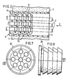
- fig. 1 is a rear view, taken in the direction of arrow I in fig. 2, of one embodiment of a sealing system according to the invention, provided with three holes for carrying three cables through an opening in a wall;
- fig. 2 is a section along line II-II in fig. 1;
- fig. 2a shows one segment of the inventive sealing system of figs. 1 and 2 prior to its insertion into the wall opening;
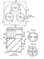
- fig. 3 is a rear view, taken in the direction of arrow III in fig. 4, and also represents a sealing system for the passage of three cables through a wall, but shows the embodiment according to the aforementioned state of the art, drawn on the same scale as figs. 1 and 2;
- fig. 4 is a section along line IV-IV in fig. 3;
- fig. 5 is a rear view, taken in the direction of arrow V in fig. 6, of another enbodiment of a sealing system according to the invention, comprising four segmental parts for carrying five cables;
- fig. 6 is a lateral view, taken in the direction of arrow VI in fig. 5;
- fig. 7 is a rear view, taken in the direction of arrow VII in fig. 8, of a further embodiment of a sealing system according to the invention, comprising eight segmental parts for carrying nine cables;
- fig. 8 is a view, taken in the direction of arrow VIII in fig. 7;
- fig. 9 is a rear view of an embodiment of a sealing system according to the invention, comprising two holes; and
- fig. 10 is a rear view of an embodiment of a sealing system according to the invention, comprising four holes, no central hole being provided.
- Referring to the drawings in detail, figs. 1 and 2 show a
wall 1, which may, for example, be a concrete wall of a basement of a building under construction, through which threeelectric cables 2 are conducted. Thewall 1 has anopening 3, which has either been left during the pouring of concrete or drilled later in the completed wall. Asmooth liner 4, which may comprise a piece of plastic pipe, is fitted in theopening 3. The threecables 2 have already been passed through the wall by the electrician. The sealing system according to the invention comprises acylindrical body 6, which is composed of two semi-cylindricalsegmental parts 7 and 8. Bothsegmental parts 7 and 8 are provided withexternal ribs 9, which lie in (imaginary) radial planes and which, while virtually inflexible, are substantially compressible. Arranged on the flat surface of eachsegmental part 7 and 8 are threesemi-cylindrical holes 11, which are provided withinternal ribs 12 disposed in (imaginary) radial planes; these ribs, while virtually inflexible, are substantially compressible. With regard to a givenhole 11, theexternal ribs 9 and theinternal ribs 12 are disposed in pairs or sets, each of which is disposed at least partially in a common (imaginary) radial plane having a predetermined axial length. - The procedure of the invention, as specified hereinabove, is implemented as follows. The
liner 4 has previously been fixed in theopening 3, for example by the builder's workers, whereupon the electrician has passed the cables through the opening. Thesegmental parts 7 and 8 are now fitted about the threecables 2, in conformity with the situation indicated in fig. 2a. The segmental halves, now jointly constituting a cylindrical body, are subsequently pushed into theliner 4, and, if necessary, pressed in with the use of a mallet. This pressing operation is continued until theflange 14 is in contact with the head of theliner 4. As fig. 2 indicates, theribs 9 are now compressed. As a result, internal compressive forces set up in the material of the cylindrical body; these forces are transmitted to theribs 12 and to theaxial contact surfaces 15 for sealing thesegmental halves 7 and 8. This causes theribs 12 to be sealingly tightened about thecables 2 and thecontact surfaces 15 to sealingly contact one another. It should be noted that, as a result of the contact of theflanges 14 of thesegments 7 and 8 with the head of theliner 4, thesegments 7 and 8, and hence their external andinternal ribs -
- Figs. 3 and 4 likewise show a sealing system for the passage of three cables similar to the
cables 2 in figs. 1 and 2. However, figs. 3 and 4 are a representation of a sealing system according to the aforementioned state of the art, on the same scale as figs. 1 and 2. In these figs. 3 and 4, use is made, according to the aforementioned state of the art, of threecylindrical bodies 106, so that a separate cylindrical body is used for each of thecables 102. For this purpose, acylindrical block 104 with threebores 105 is inserted in theopening 103 in thewall 101. The sealing mechanic new introduces the threecylindrical bodies 106 into each of thebores 105, through which the electrician has already passed acable 102, for which operation reference is made to the procedure described hereinabove. With the use of the method of sealing according to the aforementioned state of the art, evidently a considerably larger amount of material and cost of fitting will be required than is the case, when adopting the sealing method according to the invention, as explained with reference to figs. 1 and 2. Furthermore, the heretofore known sealing system requires more space for two or more cables, so that a much larger opening is required in the wall. - Figs. 5 and 6 represent a four-part segmented
cylindrical sealing body 20 according to the invention, serving a fivefold passage. - Figs. 7 and 8 represent an eight-part segmented
cylindrical body 30, which serves for a ninefold passage. - Figs. 9 and 10 respectively represent rear views of a two-part segmented
cylindrical body 40 with two holes, and a four-part segmentedcylindrical body 50 with four holes, no central hole being provided.
Claims (7)
Applications Claiming Priority (2)
| Application Number | Priority Date | Filing Date | Title |
|---|---|---|---|
| US54326683A | 1983-10-19 | 1983-10-19 | |
| US543266 | 1983-10-19 |
Publications (2)
| Publication Number | Publication Date |
|---|---|
| EP0139337A2 true EP0139337A2 (en) | 1985-05-02 |
| EP0139337A3 EP0139337A3 (en) | 1986-07-30 |
Family
ID=24167276
Family Applications (1)
| Application Number | Title | Priority Date | Filing Date |
|---|---|---|---|
| EP84201503A Withdrawn EP0139337A3 (en) | 1983-10-19 | 1984-10-17 | Multi-part sealing system |
Country Status (2)
| Country | Link |
|---|---|
| EP (1) | EP0139337A3 (en) |
| JP (1) | JPS60104870A (en) |
Cited By (19)
| Publication number | Priority date | Publication date | Assignee | Title |
|---|---|---|---|---|
| FR2647515A1 (en) * | 1989-05-25 | 1990-11-30 | Peugeot | Sealed arrangement of a crankshaft end bearing cap |
| FR2658264A1 (en) * | 1990-02-13 | 1991-08-16 | Sgn Soc Gen Tech Nouvelle | DEVICE FOR THE PASSAGE, Sealed against radiation, of a flexible supply through the protective wall of a hot enclosure. |
| NL1010333C2 (en) * | 1998-10-16 | 2000-04-18 | Artech Rubber B V | Composite sleeve-shaped sealant. |
| WO2000070290A1 (en) * | 1999-05-18 | 2000-11-23 | Hitachi Zosen Corporation | Bush for partition-through-pipe seal and multi-stage flash evaporator using the bush |
| NL1023687C2 (en) * | 2003-06-18 | 2004-12-21 | Beele Eng Bv | Seal for lead through, e.g. for pipe or cable in wall, has tips of ribs on outer and inner sides which are offset relative to each other |
| NL1023688C2 (en) * | 2003-06-18 | 2004-12-21 | Beele Eng Bv | System for sealing a space between an inner wall of a tubular opening and at least one tube or pipe received at least partially in the opening, the axis of which is substantially parallel to the axis of the opening. |
| WO2007028443A1 (en) * | 2005-07-13 | 2007-03-15 | Beele Engineering B.V. | System for sealing a space between an inner wall of a tabular opening and at least one tube or duct at least partly received in the opening |
| JP2009530555A (en) * | 2006-03-20 | 2009-08-27 | ベーレ エンフィネーリンフ ベー.フェー. | A system for dynamically sealing a conduit sleeve into which a pipe or cable is inserted |
| JP2010501813A (en) * | 2006-08-25 | 2010-01-21 | ベーレ エンフィネーリンフ ベー.フェー. | System for dynamically sealing at least one conduit through which a pipe or cable extends |
| EP2682649A1 (en) | 2012-07-04 | 2014-01-08 | Air Liquide Medical Systems | Grooved seal and use thereof to provide a fluid seal and orientation between fluid distribution elements |
| CN104653880A (en) * | 2015-03-13 | 2015-05-27 | 国家电网公司 | Cable plugging equipment and cable plugging method |
| CN105135644A (en) * | 2015-08-31 | 2015-12-09 | 江苏知民通风设备有限公司 | Air outlet for exterior wall |
| US9722404B2 (en) | 2013-02-14 | 2017-08-01 | Beele Engineering B.V. | System for sealingly holding cables which extend through an opening |
| CN108612131A (en) * | 2018-06-07 | 2018-10-02 | 中国十七冶集团有限公司 | A kind of pre-buried tube inlet water-stopping seepage-proof device of basement cable and its construction method |
| FR3073986A1 (en) * | 2017-11-21 | 2019-05-24 | Psa Automobiles Sa | PROTECTIVE DEVICE FOR ELECTRIC CABLES IN A MOTOR VEHICLE |
| US10422427B2 (en) | 2010-05-25 | 2019-09-24 | Beele Engineering B.V. | Assembly and a method for providing in an opening sealing system |
| US10544884B2 (en) | 2012-08-30 | 2020-01-28 | Beele Engineering B.V. | Sealing system for an annular space |
| WO2020036758A3 (en) * | 2018-08-14 | 2020-03-26 | Covidien Lp | Surgical devices including features to facilitate cleaning |
| RU225031U1 (en) * | 2023-12-21 | 2024-04-12 | Общество с ограниченной ответственностью "Газпром трансгаз Ухта" | CHANNEL SEALING DEVICE |
Families Citing this family (1)
| Publication number | Priority date | Publication date | Assignee | Title |
|---|---|---|---|---|
| JP2005282763A (en) * | 2004-03-30 | 2005-10-13 | C I Kasei Co Ltd | Water stop packing material and water stop structure for pipeline using this material |
Family Cites Families (5)
| Publication number | Priority date | Publication date | Assignee | Title |
|---|---|---|---|---|
| DE1786459U (en) * | 1959-01-31 | 1959-04-09 | Jung Albrecht Fa | CLOSING NIPPLE. |
| US3162412A (en) * | 1962-08-06 | 1964-12-22 | E & R Lab Service Corp | Clamping structure for control tubing or the like |
| JPS5115006Y2 (en) * | 1972-02-09 | 1976-04-20 | ||
| NL177516C (en) * | 1978-09-12 | 1985-10-01 | Pidou Bv | SEALING CUFF. |
| JPS582078Y2 (en) * | 1979-04-06 | 1983-01-13 | 株式会社ネオフレックス | electric wire holder |
-
1984
- 1984-10-17 EP EP84201503A patent/EP0139337A3/en not_active Withdrawn
- 1984-10-18 JP JP59217456A patent/JPS60104870A/en active Granted
Cited By (34)
| Publication number | Priority date | Publication date | Assignee | Title |
|---|---|---|---|---|
| FR2647515A1 (en) * | 1989-05-25 | 1990-11-30 | Peugeot | Sealed arrangement of a crankshaft end bearing cap |
| FR2658264A1 (en) * | 1990-02-13 | 1991-08-16 | Sgn Soc Gen Tech Nouvelle | DEVICE FOR THE PASSAGE, Sealed against radiation, of a flexible supply through the protective wall of a hot enclosure. |
| EP0442791A1 (en) * | 1990-02-13 | 1991-08-21 | Societe Generale Pour Les Techniques Nouvelles S.G.N. | Device for the radiation-proof passage of a flexible supply through the shielding wall of a hot cell |
| NL1010333C2 (en) * | 1998-10-16 | 2000-04-18 | Artech Rubber B V | Composite sleeve-shaped sealant. |
| EP0994287A1 (en) * | 1998-10-16 | 2000-04-19 | Artech Rubber B.V. | Composite sleeve-shaped sealing means |
| WO2000070290A1 (en) * | 1999-05-18 | 2000-11-23 | Hitachi Zosen Corporation | Bush for partition-through-pipe seal and multi-stage flash evaporator using the bush |
| WO2004111513A1 (en) * | 2003-06-18 | 2004-12-23 | Beele Engineering B.V. | System for sealing a space between a tubular opening and a tube |
| NL1023688C2 (en) * | 2003-06-18 | 2004-12-21 | Beele Eng Bv | System for sealing a space between an inner wall of a tubular opening and at least one tube or pipe received at least partially in the opening, the axis of which is substantially parallel to the axis of the opening. |
| EP1857721A2 (en) | 2003-06-18 | 2007-11-21 | Beele Engineering B.V. | System for sealing a space between a tubular opening and a tube |
| EP1857721A3 (en) * | 2003-06-18 | 2007-11-28 | Beele Engineering B.V. | System for sealing a space between a tubular opening and a tube |
| CN100394093C (en) * | 2003-06-18 | 2008-06-11 | 贝勒工程公司 | System for sealing gaps between tubular openings and tubes |
| US7802798B2 (en) | 2003-06-18 | 2010-09-28 | Beele Engineering B.V. | System for sealing a space between a tubular opening and a tube |
| NL1023687C2 (en) * | 2003-06-18 | 2004-12-21 | Beele Eng Bv | Seal for lead through, e.g. for pipe or cable in wall, has tips of ribs on outer and inner sides which are offset relative to each other |
| US8262094B2 (en) | 2005-07-13 | 2012-09-11 | Beele Engineering B.V. | System for sealing a space between an inner wall of a tubular opening and at least one tube or duct at least partly received in the opening |
| WO2007028443A1 (en) * | 2005-07-13 | 2007-03-15 | Beele Engineering B.V. | System for sealing a space between an inner wall of a tabular opening and at least one tube or duct at least partly received in the opening |
| JP2009530555A (en) * | 2006-03-20 | 2009-08-27 | ベーレ エンフィネーリンフ ベー.フェー. | A system for dynamically sealing a conduit sleeve into which a pipe or cable is inserted |
| US9528636B2 (en) | 2006-03-20 | 2016-12-27 | Beele Engineering B.V. | System for dynamically sealing a conduit sleeve through which a pipe or cable extends |
| JP4890608B2 (en) * | 2006-03-20 | 2012-03-07 | ベーレ エンフィネーリンフ ベー.フェー. | A system for dynamically sealing a conduit sleeve into which a pipe or cable is inserted |
| JP4890617B2 (en) * | 2006-08-25 | 2012-03-07 | ベーレ エンフィネーリンフ ベー.フェー. | System for dynamically sealing at least one conduit through which a pipe or cable extends |
| JP2010501813A (en) * | 2006-08-25 | 2010-01-21 | ベーレ エンフィネーリンフ ベー.フェー. | System for dynamically sealing at least one conduit through which a pipe or cable extends |
| US8490353B2 (en) | 2006-08-25 | 2013-07-23 | Beele Engineering B.V. | System for dynamically sealing at least one conduit through which a pipe or cable extends |
| US8833014B2 (en) | 2006-08-25 | 2014-09-16 | Beele Engineering B.V. | System for dynamically sealing at least one conduit through which a pipe or cable extends |
| US10422427B2 (en) | 2010-05-25 | 2019-09-24 | Beele Engineering B.V. | Assembly and a method for providing in an opening sealing system |
| FR2993030A1 (en) * | 2012-07-04 | 2014-01-10 | Air Liquide Medical Systems | GROOVED SEAL AND USE THEREFOR TO ENSURE FLUID SEALING AND ORIENTATION BETWEEN FLUID DISPENSING ELEMENTS |
| EP2682649A1 (en) | 2012-07-04 | 2014-01-08 | Air Liquide Medical Systems | Grooved seal and use thereof to provide a fluid seal and orientation between fluid distribution elements |
| US10544884B2 (en) | 2012-08-30 | 2020-01-28 | Beele Engineering B.V. | Sealing system for an annular space |
| US9722404B2 (en) | 2013-02-14 | 2017-08-01 | Beele Engineering B.V. | System for sealingly holding cables which extend through an opening |
| CN104653880A (en) * | 2015-03-13 | 2015-05-27 | 国家电网公司 | Cable plugging equipment and cable plugging method |
| CN104653880B (en) * | 2015-03-13 | 2017-02-01 | 国家电网公司 | Mud plugging forming equipment and forming plugging method |
| CN105135644A (en) * | 2015-08-31 | 2015-12-09 | 江苏知民通风设备有限公司 | Air outlet for exterior wall |
| FR3073986A1 (en) * | 2017-11-21 | 2019-05-24 | Psa Automobiles Sa | PROTECTIVE DEVICE FOR ELECTRIC CABLES IN A MOTOR VEHICLE |
| CN108612131A (en) * | 2018-06-07 | 2018-10-02 | 中国十七冶集团有限公司 | A kind of pre-buried tube inlet water-stopping seepage-proof device of basement cable and its construction method |
| WO2020036758A3 (en) * | 2018-08-14 | 2020-03-26 | Covidien Lp | Surgical devices including features to facilitate cleaning |
| RU225031U1 (en) * | 2023-12-21 | 2024-04-12 | Общество с ограниченной ответственностью "Газпром трансгаз Ухта" | CHANNEL SEALING DEVICE |
Also Published As
| Publication number | Publication date |
|---|---|
| EP0139337A3 (en) | 1986-07-30 |
| JPS60104870A (en) | 1985-06-10 |
| JPH0541868B2 (en) | 1993-06-24 |
Similar Documents
| Publication | Publication Date | Title |
|---|---|---|
| EP0139337A2 (en) | Multi-part sealing system | |
| US3686747A (en) | Electrically insulating pipe union | |
| US4242164A (en) | Gasket for sealing a pipe in a porthole | |
| US4418457A (en) | Apparatus and process for expanding to join a tube into a tube sheet opening | |
| JPS61164881U (en) | ||
| US4071265A (en) | Threaded mechanical joint wall sleeve | |
| US5288947A (en) | Cable junction box | |
| GB2328483A (en) | Plastic pipe compression coupler | |
| GB1157456A (en) | Prefabricated, Electrically Insulating Joint, for Liquid- or Gas-Conveying Metal Ducts. | |
| US4565381A (en) | Self aligning concrete pipe with configured joint | |
| US4756784A (en) | Method of making pipe-joint gasket | |
| US5709411A (en) | Draft compensating coupling member | |
| EP0113193A1 (en) | Restrained mechanical pipe joint | |
| JPH05227638A (en) | Cable sleeve composed of vertically split type casing | |
| US3982777A (en) | Pipe connection to manholes and the like | |
| GB2341014A (en) | A seal to surround a cable on entry to a junction box | |
| US3838205A (en) | Electrically conductive pipe coupling gasket | |
| US4300792A (en) | Pipe assembly | |
| JPS629088A (en) | Pipe joint and manufacture thereof | |
| EP0083135B1 (en) | A pipe coupling or branch pipe | |
| GB1443578A (en) | Method of joining the conductors of electric cables | |
| US6739598B1 (en) | Seal between a conduit and cable | |
| GB2181000A (en) | Cable closure | |
| GB1313242A (en) | Pipe couplings | |
| US4174112A (en) | Seal assembly |
Legal Events
| Date | Code | Title | Description |
|---|---|---|---|
| PUAI | Public reference made under article 153(3) epc to a published international application that has entered the european phase |
Free format text: ORIGINAL CODE: 0009012 |
|
| AK | Designated contracting states |
Designated state(s): AT BE CH DE FR GB IT LI LU NL SE |
|
| PUAL | Search report despatched |
Free format text: ORIGINAL CODE: 0009013 |
|
| AK | Designated contracting states |
Kind code of ref document: A3 Designated state(s): AT BE CH DE FR GB IT LI LU NL SE |
|
| 17P | Request for examination filed |
Effective date: 19870116 |
|
| 17Q | First examination report despatched |
Effective date: 19871204 |
|
| STAA | Information on the status of an ep patent application or granted ep patent |
Free format text: STATUS: THE APPLICATION IS DEEMED TO BE WITHDRAWN |
|
| 18D | Application deemed to be withdrawn |
Effective date: 19891121 |
|
| RIN1 | Information on inventor provided before grant (corrected) |
Inventor name: MEYER-SWANTEE, KLAUS BERTIL |