EP0442791A1 - Device for the radiation-proof passage of a flexible supply through the shielding wall of a hot cell - Google Patents
Device for the radiation-proof passage of a flexible supply through the shielding wall of a hot cell Download PDFInfo
- Publication number
- EP0442791A1 EP0442791A1 EP91400322A EP91400322A EP0442791A1 EP 0442791 A1 EP0442791 A1 EP 0442791A1 EP 91400322 A EP91400322 A EP 91400322A EP 91400322 A EP91400322 A EP 91400322A EP 0442791 A1 EP0442791 A1 EP 0442791A1
- Authority
- EP
- European Patent Office
- Prior art keywords
- flexible
- radiation
- olives
- sheath
- passage
- Prior art date
- Legal status (The legal status is an assumption and is not a legal conclusion. Google has not performed a legal analysis and makes no representation as to the accuracy of the status listed.)
- Granted
Links
Images


Classifications
-
- G—PHYSICS
- G21—NUCLEAR PHYSICS; NUCLEAR ENGINEERING
- G21F—PROTECTION AGAINST X-RADIATION, GAMMA RADIATION, CORPUSCULAR RADIATION OR PARTICLE BOMBARDMENT; TREATING RADIOACTIVELY CONTAMINATED MATERIAL; DECONTAMINATION ARRANGEMENTS THEREFOR
- G21F7/00—Shielded cells or rooms
- G21F7/005—Shielded passages through walls; Locks; Transferring devices between rooms
Definitions
- the present invention relates to the field of biological protection with respect to ionizing and / or neutron radiation, as is the case for example in nuclear energy where enclosures, subjected to such radiation and called hot enclosures , are separated by a special concrete wall from the work area in which the staff work.
- these flexible supplies cross the protective wall in cylindrical conduits having a curved shape (called S-shaped crossings) or having a rectilinear shape (called straight crossings).
- the conduit consists of a curved (S-shaped crossing) or straight (straight crossing) metal tube embedded directly during the manufacturing process in the concrete wall itself.
- a plug is placed at each end of the duct, this plug being made of a material absorbing radiation (alpha and / or beta and / or gamma and / or neutron) and in this plug baffles have machined through which the flexible feed passes.
- the function of such caps is to ensure non-passage of radiation and contaminants from the cell and through the crossing.
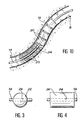
- FIG. 1 there is shown schematically in section, the concrete wall 2 which separates in a nuclear installation, the radioactive hot enclosure 4 from the work area 6 where the personnel work.
- the actual crossing of the wall is carried out by a curved conduit 8 hollowed out in the concrete and coated internally with a sheath 10 intended to protect the concrete from any mechanical degradation.
- the personnel protection is supplemented by a cast iron or steel plate 12 located on one of the faces of the wall 2. In this case, the sheath 8 obviously also passes through this metal plate 12.
- the sheath 10 which opens at one of its ends in the hot zone 4 and at the other end in the non-active zone 6 is therefore perfectly suitable for serving as a passage for any flexible supply such as cables or flexible tubes for conducting fluids, which thus makes it possible to supply the active zone 4, generally closed, in energy and in a certain number of fluids necessary for carrying out the operations which take place there.
- the sheath 10 does not contain materials capable of stopping radiation, the protective function against these is only ensured by its S shape which opposes the progression in a straight line of electromagnetic photons and also neutrons, thus that possibly by the plates 12 of suitable material embedded in the concrete wall.
- the calculation shows that to guarantee biological protection of an acceptable quality, one cannot exceed for the sheath 10 an internal diameter of the order of 35 mm, otherwise there is a risk of direct leaks, either by collimation of photons or neutrons on the wall of the sheath 10. Indeed, if theoretically, a photon appearing at the entry of the sheath 10 in cell 4 and propagating in a straight line cannot exceed point B marked in FIG. 1, it is not excluded that, by phenomena of subsequent successive reflections in C and D on the walls, according to paths marked in dotted lines in FIG. 1, certain photons nevertheless cross the entirety from the wall 2.
- the present invention specifically relates to a device for the radiation-tight passage of such a flexible supply through the biological protection wall of a hot enclosure which allows, while possibly increasing the diameter of the crossing sleeves beyond 35 mm, to maintain a total seal against radiation.
- This device for the passage, radiation-tight, of a flexible supply through the biological protection wall of a hot enclosure comprising a curved conduit, in particular of S shape, crossing the wall, coated with a sheath in radiation absorbing material and open to its two ends located respectively one in the hot zone and the other in the working zone, is characterized in that the flexible supply is provided, at least on a portion of the part corresponding to its path in the duct, solid removable parts, made of a radiation protection material compatible with the sheath material, said parts surround the flexible supply at least in place in the manner of the beads of a necklace and ensure both its setting in place by sliding in the conduit and the sealing of this curved conduit with respect to the rectilinear propagation of the photons of electromagnetic radiation which can be introduced therein.
- the main means of the invention consists of removable solid parts which are surrounded from place to place by the flexible supply which must pass through the duct, the location, the size and the material of which these different parts are made. being massive enough to completely block all possible paths for electromagnetic radiation.
- the massive parts which surround the flexible supply in its path inside the curved conduit in the manner in which pearls are threaded on a collar can take extremely varied forms as long as they fulfill the function assigned to them.
- these solid parts are spherical balls of diameter substantially equal to the internal diameter of the sheath and pierced along one of their diameters with a passage for flexible feeding.
- the solid parts are straight cylinders with a circular base of diameter substantially equal to the internal diameter of the sheath and pierced along their axis with a passage for flexible feeding.
- these solid parts are cylindrical olives in two integral parts and having, for the passage of the flexible supply, a conduit eccentric relative to the axis of the cylinder, so as to allow the helical mounting of the different olives around the flexible food.
- This method of fixing massive parts to the flexible supply allows, by virtue of the eccentric passage in the different successive parts, a helical distribution around the flexible supply of all of these same parts, which strengthens the seal. by further complicating the path for photons or neutrons which would nevertheless tend to introduce themselves into the curved duct and progress there.
- the massive pieces are no longer, as in the previous embodiments, distributed discreetly along the flexible supply, but on the contrary constitute a continuous flexible reinforcement all along the crossing thereof in the curved conduit.
- these massive pieces are cylindrical olives in two integral parts each having a concave spherical end face and a convex spherical end face of the same radius of curvature, so that the different successive olives fit one into the other in a swiveling manner and constitute a continuous flexible frame around the flexible supply.
- the material constituting the solid parts in each of the modes of implementation is chosen so as to have as good a coefficient of friction as possible on the material constituting the sheath which covers the interior of the curved duct.
- the skilled person will know in each particular case to choose the suitable materials among those which have a high capture section with respect to ionizing radiation.
- the invention also includes a cable gland traversed by power supply and closing at least one of the openings of the curved duct to improve protection against particulate radiation, such as in particular radiation alpha and beta.
- This cable gland which can be placed, preferably on the side of the clean area 6 for ease of access for personnel, can also be placed on the side of the contaminated cell 4, has the additional advantage of maintaining the supply flexible in place, since it passes through the cable gland.
- FIG. 2 a certain number of elements have been shown common with those of FIG. 1, designating them using the same number of references.
- the technical problem to be solved consists in passing the wall 2 through a flexible electric cable 14 which crosses the wall 2 via the curved conduit 8 and opens at 16 at the same time at the end of the latter into the hot zone 4 and at 18 by the other end of this same conduit 8 in the working area 6.
- a certain number of solid pieces or olives 20 which the cable crosses and whose external dimensions allow progression by sliding inside the sheath 10 coating the curved conduit 8.
- FIG. 2 to better illustrate the invention, the space between the outer surfaces of the olives and the sheath has been exaggerated. It is obvious that the smaller this space, the less radiation or particle leaks.
- the sheath 10 and the solid parts 20 can be made of a heavy metal such as lead which allows good sliding of the parts 20 in the sheath 10 while ensuring an almost total seal against electromagnetic radiation which could have tendency to enter the sheath 10 to pass through the wall 2.
- a heavy metal such as lead which allows good sliding of the parts 20 in the sheath 10 while ensuring an almost total seal against electromagnetic radiation which could have tendency to enter the sheath 10 to pass through the wall 2.
- any material which absorbs radiation and / or neutrons (as the case may be) and which has anti-friction properties is suitable for olives.
- This material can be homogeneous (lead) or heterogeneous (steel coated with an anti-friction material). It goes without saying that when there is a coating, it must resist ambient irradiation.
- the solid parts 20 which surround the electric cable 14 in place are removable, that is to say that they can be put in place around the cable 14 and removed at will when the need arises. actually feel it.
- the diameter of the sheath 10 no longer needs to be limited, as in the prior art, to a dimension of the order of 35 mm to achieve good sealing, and it is clear that this is simply the dimension of the solid parts 20 which, in connection with the diameter of the sheath 10, allows this sealing to be achieved.
- the curvature of the conduit 8 is such that the orifice 16 of the latter situated in the hot zone 4 is at a lower level of the orifice 18 of this same conduit 8 in the working zone 6.
- This arrangement is specially sought after and allows the introduction of the cable 14 provided with these massive pieces 20 by descent by gravity from the opening 18, a complementary traction of the latter from the active area 4 may nevertheless be necessary to ensure placing the assembly in the conduit 8.
- the solid pieces 20 behave in a way like the pearls of a necklace surrounding the flexible cable 14 and these same pearls can receive, within the framework of the invention, all the possible desirable shapes, and in particular a certain number of which will now be described below.
- FIG 3 there is shown an embodiment of the parts 20 which is one of the simplest since they consist in this example of balls 22 having a diametrical passage 24 for the cable or flexible frame 14 which passes through it .
- the solid part is a straight cylinder with a circular base 26 also having an axial passage channel 24 for the cable 14.
- FIG 5 there is shown another embodiment of the massive parts 20 which are produced in this case in the form of cylindrical olives 28 composed of two parts 28a and 28b which can be fixed to one another using any means known for this purpose, for example screws 30.
- a channel 24 for passing the cable 14, not shown is produced using two complementary and juxtaposable hollow half-cylinders 24a and 24b which, when secured using the screws 30 the two halves 28a and 28b of the olive 28 constitute a continuous circular cylindrical channel for the passage of the cable 14.
- this channel 24 which is its eccentricity by a distance e relative to the axis of the olive 28, which allows eccentricity of the cable 14 relative to the axis of the sheath, and, by successive mounting of the different olives 28 in a helix around this cable 14, as shown in FIG. 6, obtain an overall arrangement likely to reinforce the seal tee to the radiation of the curved duct 8.
- FIG. 6 provision has also been made for strengthening the protection against irradiating particles of small dimensions which arise in the hot enclosure 4, and which could pass through the crossing using two plugs.
- cable gland 32 and 34 located around the cable 14 in the openings of the conduit 8.
- dangerous radioactive radiation is not limited to only electromagnetic X or gamma photons but can also contain alpha and beta particles sometimes emitted with energy. important kinetics or neutrons.
- the cable glands 32 and 34 are sufficient to prevent them from accessing the conduit 8 and consequently the passage through the wall 2.
- the biological protection is further reinforced at the using two local absorbent metal plates surrounding the orifices of the curved channel 8 and which may for example be made of steel or lead.
- FIG. 6 there is shown diagrammatically in dashed lines a remote manipulator crossing the wall 2 and allowing, using a driving handle 40, remote manipulation by a driven clamp 41.
- FIG. 7 shows in the sheath 10, one of the olives 28 in FIG. 5 crossed by the cable 14 which we can clearly see, in this figure, that it is eccentric relative to the axis of the olive 28 and , consequently, relative to the axis of the sleeve 10.
- FIGS. 8 and 9 which correspond to sections AB and XY of the device of FIG. 6 make it possible to understand the helical mounting already explained of an olive 28 provided with its assembly screws 30 around the flexible cable 14. In fact, between FIG. 8 and FIG. 9 observe a 180 ° rotation of the olive 28 relative to the cable 14.
- FIG. 10 shows a particularly advantageous embodiment of the invention in which the various solid pieces or olives are strung contiguously. on the cable 14 and produce a sort of flexible frame passing through the sheath 10 which they completely fill thanks to their characteristics explained below.
- each of the olives or solid pieces 20 consists of a straight cylinder with a circular base pierced in its center with a channel 24 for the passage of the cable 14, and the ends of each of the olives 20 are made of spherical parts, alternately concave and convex, so that the different pearls 20 fit continuously and swiveling one inside the other to form a flexible frame which slides without difficulty at inside of the sheath 10 fitted to the walls of the curved duct 8.
Abstract
Description
La présente invention se rapporte au domaine de la protection biologique vis-à-vis des rayonnements ionisants et/ou neutroniques, comme c'est le cas par exemple dans l'énergie nucléaire où des enceintes, soumises à de tels rayonnements et dites enceintes chaudes, sont séparées par un mur en béton spécial de la zone de travail dans laquelle évolue le personnel.The present invention relates to the field of biological protection with respect to ionizing and / or neutron radiation, as is the case for example in nuclear energy where enclosures, subjected to such radiation and called hot enclosures , are separated by a special concrete wall from the work area in which the staff work.
De façon plus précise, pour assurer l'alimentation des différents matériels qui sont présents dans la cellule chaude interdite à l'homme, il est nécessaire de pouvoir faire passer, au travers de la paroi de la cellule, des alimentations souples, telles que par exemple des câbles électriques ou des tuyauteries d'amenée et/ou d'évacuation de certains fluides.More specifically, to ensure the supply of the various materials which are present in the hot cell prohibited to humans, it is necessary to be able to pass, through the wall of the cell, flexible supplies, such as by example of electric cables or pipes for the supply and / or evacuation of certain fluids.
De façon classique et connue, ces alimentations souples traversent le mur de protection dans des conduits cylindriques ayant une forme courbe (dites traversées en S) ou ayant une forme rectiligne (dites traversées droites).In a conventional and known manner, these flexible supplies cross the protective wall in cylindrical conduits having a curved shape (called S-shaped crossings) or having a rectilinear shape (called straight crossings).
Dans les deux cas, le conduit est constitué par un tube métallique courbe (traversée en S) ou droit (traversée droite) noyé directement lors de la fabrication dans le mur de béton lui-même.In both cases, the conduit consists of a curved (S-shaped crossing) or straight (straight crossing) metal tube embedded directly during the manufacturing process in the concrete wall itself.
Dans le cas de la traversée droite, un bouchon est placé à chaque extrémité du conduit, ce bouchon étant fait en un matériau absorbant les rayonnements (alpha et/ou béta et/ou gamma et/ou neutroniques) et dans ce bouchon des chicanes ont été usinées dans lesquelles passe l'alimentation souple. De tels bouchons ont pour fonction d'assurer le non passage des rayonnements et des contaminants à partir de la cellule et par l'intermédiaire de la traversée.In the case of the straight crossing, a plug is placed at each end of the duct, this plug being made of a material absorbing radiation (alpha and / or beta and / or gamma and / or neutron) and in this plug baffles have machined through which the flexible feed passes. The function of such caps is to ensure non-passage of radiation and contaminants from the cell and through the crossing.
Dans le cas de la traversée en S, la forme en S du conduit suffit à arrêter le rayonnement par collimation. La figure 1 montre cette réalisation.In the case of the S crossing, the S shape of the conduit is sufficient to stop the radiation by collimation. Figure 1 shows this realization.
Sur cette figure 1, on a représenté schématiquement en coupe, le mur de béton 2 qui sépare dans une installation nucléaire, l'enceinte chaude radioactive 4 de la zone de travail 6 où évolue le personnel. La traversée du mur proprement dite est réalisée par un conduit courbe 8 creusé dans le béton et revêtu intérieurement d'un fourreau 10 destiné à protéger le béton de toute dégradation mécanique. La protection du personnel est complétée par une plaque de fonte ou d'acier 12 située sur une des faces du mur 2. Dans ce cas, le fourreau 8 traverse évidemment également cette plaque métallique 12. Le fourreau 10 qui débouche à l'une de ses extrémités dans la zone chaude 4 et à l'autre extrémité dans la zone non active 6 est donc parfaitement apte à servir de passage à toute alimentation souple tels que câbles ou tubes souples de conduite de fluides, ce qui permet ainsi d'alimenter la zone active 4, généralement fermée, en énergie et en un certain nombre de fluides nécessaires à la réalisation des opérations qui s'y déroulent.In this figure 1, there is shown schematically in section, the
Le fourreau 10 ne contenant pas de matériaux susceptibles d'arrêter les rayonnements, la fonction de protection contre ceux-ci est uniquement assurée par sa forme en S qui s'oppose à la progression en ligne droite des photons électromagnétiques et également des neutrons, ainsi qu'éventuellement par les plaques 12 en matériau adéquat noyé dans la paroi du béton.The
Malheureusement, dans une réalisation de ce genre, le calcul montre que pour garantir une protection biologique d'une qualité acceptable, on ne peut dépasser pour le fourreau 10 un diamètre interne de l'ordre de 35 mm, faute de quoi on risque soit des fuites directes, soit des fuites par collimation des photons ou des neutrons sur la paroi du fourreau 10. En effet, si théoriquement, un photon se présentant à l'entrée du fourreau 10 dans la cellule 4 et se propageant en ligne droite ne peut dépasser le point B marqué sur la figure 1, il n'est pas exclu que, par des phénomènes de réflexions successives ultérieures en C et D sur les parois, selon des trajets marqués en pointillés sur la figure 1, certains photons traversent néanmoins l'intégralité du mur 2.Unfortunately, in an embodiment of this kind, the calculation shows that to guarantee biological protection of an acceptable quality, one cannot exceed for the
C'est la raison pour laquelle on limite le diamètre des fourreaux 10 aux alentours de 35 mm car, pour une épaisseur de mur donnée et une courbure donnée du conduit 8, il est clair que les risques de fuites sont d'autant plus grands que le diamètre du fourreau 10 est élevé.This is the reason why the diameter of the
La présente invention a précisément pour objet un dispositif pour le passage étanche aux rayonnements d'une telle alimentation souple au travers de la paroi de protection biologique d'une enceinte chaude qui permet, tout en augmentant éventuellement le diamètre des fourreaux de traversée au-delà de 35 mm, de maintenir une étanchéité totale aux rayonnements.The present invention specifically relates to a device for the radiation-tight passage of such a flexible supply through the biological protection wall of a hot enclosure which allows, while possibly increasing the diameter of the crossing sleeves beyond 35 mm, to maintain a total seal against radiation.
Ce dispositif pour le passage, étanche aux rayonnements, d'une alimentation souple au travers de la paroi de protection biologique d'une enceinte chaude, comportant un conduit courbe, notamment en forme de S, traversant la paroi, revêtu d'un fourreau en matériau absorbant les rayonnements et ouvert à ses deux extrémités situées respectivement l'une dans la zone chaude et l'autre dans la zone de travail, se caractérise en ce que l'alimentation souple est munie, au moins sur une portion de la partie correspondant à son trajet dans le conduit, de pièces massives amovibles, faites en un matériau de protection contre les rayonnements compatible avec le matériau du fourreau, lesdites pièces entourent l'alimentation souple au moins de place en place à la manière des perles d'un collier et assurent à la fois sa mise en place par glissement dans le conduit et l'étanchéité de ce conduit courbe vis-à-vis de la propagation rectiligne des photons de rayonnement électromagnétique qui peuvent s'y introduire.This device for the passage, radiation-tight, of a flexible supply through the biological protection wall of a hot enclosure, comprising a curved conduit, in particular of S shape, crossing the wall, coated with a sheath in radiation absorbing material and open to its two ends located respectively one in the hot zone and the other in the working zone, is characterized in that the flexible supply is provided, at least on a portion of the part corresponding to its path in the duct, solid removable parts, made of a radiation protection material compatible with the sheath material, said parts surround the flexible supply at least in place in the manner of the beads of a necklace and ensure both its setting in place by sliding in the conduit and the sealing of this curved conduit with respect to the rectilinear propagation of the photons of electromagnetic radiation which can be introduced therein.
Comme on le voit, le moyen principal de l'invention est constitué par des pièces massives amovibles dont on entoure de place en place l'alimentation souple qui doit traverser le conduit, l'emplacement, la dimension et le matériau constitutif de ces différentes pièces massives étant de nature à obturer de façon complète tous les trajets possibles pour des rayonnements électromagnétiques.As can be seen, the main means of the invention consists of removable solid parts which are surrounded from place to place by the flexible supply which must pass through the duct, the location, the size and the material of which these different parts are made. being massive enough to completely block all possible paths for electromagnetic radiation.
Selon l'invention, les pièces massives qui entourent l'alimentation souple dans son trajet à l'intérieur du conduit courbe à la manière dont des perles sont enfilées sur un collier, peuvent revêtir des formes extrêmement variées dès lors qu'elles remplissent la fonction d'étanchéité qui leur est assignée.According to the invention, the massive parts which surround the flexible supply in its path inside the curved conduit in the manner in which pearls are threaded on a collar, can take extremely varied forms as long as they fulfill the function assigned to them.
Dans un premier mode de mise en oeuvre particulièrement simple, ces pièces massives sont des billes sphériques de diamètre sensiblement égal au diamètre interne du fourreau et percées selon un de leur diamètre d'un passage pour l'alimentation souple.In a first particularly simple embodiment, these solid parts are spherical balls of diameter substantially equal to the internal diameter of the sheath and pierced along one of their diameters with a passage for flexible feeding.
Dans un deuxième mode de mise en oeuvre de l'invention, les pièces massives sont des cylindres droits à base circulaire de diamètre sensiblement égal au diamètre interne du fourreau et percées selon leur axe d'un passage pour l'alimentation souple.In a second embodiment of the invention, the solid parts are straight cylinders with a circular base of diameter substantially equal to the internal diameter of the sheath and pierced along their axis with a passage for flexible feeding.
Selon une autre variante également très intéressante de la présente invention, ces pièces massives sont des olives cylindriques en deux parties solidarisables et présentant, pour le passage de l'alimentation souple, un conduit excentré par rapport à l'axe du cylindre, de façon à permettre le montage en hélice des différentes olives autour de l'alimentation souple. Ce mode de fixation des pièces massives sur l'alimentation souple, permet, grâce au passage excentré dans les différentes pièces successives, une répartition en hélice autour de l'alimentation souple de l'ensemble de ces mêmes pièces, ce qui renforce l'étanchéité en compliquant davantage le trajet pour des photons ou des neutrons qui auraient tendance néanmoins à s'introduire dans le conduit courbe et à y progresser.According to another also very interesting variant of the present invention, these solid parts are cylindrical olives in two integral parts and having, for the passage of the flexible supply, a conduit eccentric relative to the axis of the cylinder, so as to allow the helical mounting of the different olives around the flexible food. This method of fixing massive parts to the flexible supply, allows, by virtue of the eccentric passage in the different successive parts, a helical distribution around the flexible supply of all of these same parts, which strengthens the seal. by further complicating the path for photons or neutrons which would nevertheless tend to introduce themselves into the curved duct and progress there.
Dans un autre mode de réalisation, également très intéressant, les pièces massives ne sont plus, comme dans les modes de mise en oeuvre précédents, réparties de façon discrète le long de l'alimentation souple, mais constituent au contraire une armature flexible continue tout le long de la traversée de celle-ci dans le conduit courbe. A cet effet, ces pièces massives sont des olives cylindriques en deux parties solidarisables ayant chacune une face terminale sphérique concave et une face terminale sphérique convexe de même rayon de courbure, de façon que les différentes olives successives s'emboîtent l'une dans l'autre de manière rotulante et constituent une armature flexible continue autour de l'alimentation souple.In another embodiment, also very interesting, the massive pieces are no longer, as in the previous embodiments, distributed discreetly along the flexible supply, but on the contrary constitute a continuous flexible reinforcement all along the crossing thereof in the curved conduit. For this purpose, these massive pieces are cylindrical olives in two integral parts each having a concave spherical end face and a convex spherical end face of the same radius of curvature, so that the different successive olives fit one into the other in a swiveling manner and constitute a continuous flexible frame around the flexible supply.
Bien entendu, le matériau constituant les pièces massives dans chacun des modes de mise en oeuvre est choisi de façon à avoir un aussi bon coefficient de frottement que possible sur le matériau constituant le fourreau qui revêt l'intérieur du conduit courbe. A ce sujet, l'homme de métier saura dans chaque cas particulier choisir les matériaux convenables parmi ceux qui ont une section de capture élevée vis-à-vis des rayonnements ionisants.Of course, the material constituting the solid parts in each of the modes of implementation is chosen so as to have as good a coefficient of friction as possible on the material constituting the sheath which covers the interior of the curved duct. On this subject, the skilled person will know in each particular case to choose the suitable materials among those which have a high capture section with respect to ionizing radiation.
Dans certains modes de mise en oeuvre, l'invention comporte également un presse-étoupe traversé par alimentation et obturant au moins l'une des ouvertures du conduit courbe pour parfaire la protection vis-à-vis des rayonnements particulaires, tels que notamment les rayonnements alpha et béta.In certain embodiments, the invention also includes a cable gland traversed by power supply and closing at least one of the openings of the curved duct to improve protection against particulate radiation, such as in particular radiation alpha and beta.
Ce presse-étoupe qui peut être placé, de préférence du côté de la zone propre 6 pour des facilités d'accès du personnel, peut l'être également du côté de la cellule contaminée 4, présente l'avantage supplémentaire de maintenir l'alimentation souple en place, puisque celle-ci traverse le presse-étoupe.This cable gland which can be placed, preferably on the side of the clean area 6 for ease of access for personnel, can also be placed on the side of the contaminated
De toute façon, l'invention sera mieux comprise en se référant à la description qui suit de plusieurs exemples de mise en oeuvre de celle-ci, exemples qui seront donnés à titre illustratif et non limitatif en se référant aux figures 2 à 10 :
- la figure 2 représente schématiquement le principe général de l'invention ;
- la figure 3 représente un modèle de pièces massives ou olives de forme rigoureusement sphérique ;
- la figure 4 représente une forme particulière de pièces massives ou d'olives sous forme de cylindre droit à base circulaire ;
- la figure 5 représente, avant leur assemblage, les deux parties d'une olive cylindrique droite percée d'un passage excentré par rapport à son axe de symétrie ;
- la figure 6 représente l'implantation possible des olives de la figure 5 selon une disposition en hélice autour de l'alimentation souple ;
- la figure 7 représente à plus grande échelle, une olive selon la figure 5 montée dans son fourreau ;
- les figures 8 et 9 représentent les coupes respectives selon A, B et X,Y de la figure 6 de deux olives montées avec un décalage de 180° autour de l'axe du fourreau ;
- la figure 10 représente enfin un autre mode de mise en oeuvre de l'invention dans lequel les différentes olives ou pièces massives sont constituées d'un assemblage continu de pièces cylindriques à extrémité sphérique alternativement concave et convexe s'emboîtant de façon rotulante les unes dans les autres.
- FIG. 2 schematically represents the general principle of the invention;
- FIG. 3 represents a model of massive pieces or olives of strictly spherical shape;
- FIG. 4 represents a particular form of solid pieces or of olives in the form of a straight cylinder with a circular base;
- Figure 5 shows, before their assembly, the two parts of a straight cylindrical olive pierced with an eccentric passage relative to its axis of symmetry;
- Figure 6 shows the possible implantation of the olives of Figure 5 in a helical arrangement around the flexible feed;
- Figure 7 shows on a larger scale, an olive according to Figure 5 mounted in its sheath;
- Figures 8 and 9 show the respective sections along A, B and X, Y of Figure 6 of two olives mounted with a 180 ° offset around the axis of the sheath;
- FIG. 10 finally represents another embodiment of the invention in which the different olives or massive pieces consist of a continuous assembly of cylindrical pieces with spherical end alternately concave and convex interlocking in a swiveling manner others.
En se référant à la figure 2, on va décrire maintenant le moyen général de l'invention tel qu'il est commun à tous les modes de mise en oeuvre de celle-ci.Referring to Figure 2, we will now describe the general means of the invention as it is common to all modes of implementation thereof.
Sur cette figure 2, on a représenté un certain nombre d'éléments communs avec ceux de la figure 1, en les désignant à l'aide du même nombre de références.In this FIG. 2, a certain number of elements have been shown common with those of FIG. 1, designating them using the same number of references.
Le problème technique à résoudre consiste à faire traverser le mur 2 par un câble électrique souple 14 qui traverse le mur 2 par l'intermédiaire du conduit courbe 8 et débouche à la fois en 16 par l'extrémité de ce dernier dans la zone chaude 4 et en 18 par l'autre extrémité de ce même conduit 8 dans la zone de travail 6. Conformément à l'invention, sont placées, autour du câble électrique 14, un certain nombre de pièces massives ou olives 20 que le câble traverse et dont les dimensions extérieures permettent la progression par glissement à l'intérieur du fourreau 10 revêtant le conduit courbe 8. Sur la figure 2, pour mieux illustrer l'invention, on a exagéré l'espace entre les surfaces externes des olives et le fourreau. Il est bien évident que plus cet espace est réduit, moins il y a de fuites de rayonnement ou de particules. A titre d'exemple, le fourreau 10 et les pièces massives 20 peuvent être réalisés en un métal lourd tel que le plomb qui permet un bon glissement des pièces 20 dans le fourreau 10 tout en assurant une étanchéité quasi totale au rayonnement électromagnétique qui pourrait avoir tendance à s'introduire dans le fourreau 10 pour traverser le mur 2. De façon générale, tout matériau absorbant les rayonnements et/ou les neutrons (selon le cas), et qui possède des propriétés anti-friction convient pour les olives. Ce matériau peut être homogène (plomb) ou hétérogène (acier revêtu d'un matériau anti-friction). Il va sans dire que lorsqu'il y a revêtement, celui-ci doit résister à l'irradiation ambiante. Selon l'invention, les pièces massives 20 qui entourent de place en place le câble électrique 14 sont amovibles, c'est-à-dire qu'elles peuvent être mises en place autour du câble 14 et retirées à volonté lorsque la nécessité s'en fait sentir. Conformément à l'invention, le diamètre du fourreau 10 n'a plus besoin d'être limité comme dans l'art antérieur à une dimension de l'ordre de 35 mm pour parvenir à une bonne étanchéité et il est clair que c'est simplement la dimension des pièces massives 20 qui, en liaison avec le diamètre du fourreau 10, permet la réalisation de cette étanchéité.The technical problem to be solved consists in passing the
Sur cette figure 2 on voit que la courbure du conduit 8 est telle que l'orifice 16 de ce dernier situé dans la zone chaude 4 est à un niveau inférieur de l'orifice 18 de ce même conduit 8 dans la zone de travail 6. Cette disposition est spécialement recherchée et permet l'introduction du câble 14 muni de ces pièces massives 20 par descente par gravité à partir de l'ouverture 18, une traction complémentaire de ce dernier à partir de la zone active 4 pouvant être néanmoins nécessaire pour assurer la mise en place de l'ensemble dans le conduit 8.In this FIG. 2, it can be seen that the curvature of the
Comme indiqué précédemment, les pièces massives 20 se comportent en quelque sorte comme les perles d'un collier entourant le câble souple 14 et ces mêmes perles peuvent recevoir dans le cadre de l'invention toutes les formes désirables possibles, et en particulier un certain nombre d'entre elles qui vont être décrites maintenant ci-après.As indicated above, the
Sur la figure 3, on a représenté un mode de réalisation des pièces 20 qui est l'un des plus simples puisque celles-ci sont constituées dans cet exemple de billes 22 comportant un passage diamétral 24 pour le câble ou armature souple 14 qui le traverse.In Figure 3, there is shown an embodiment of the
Dans l'exemple de mise en oeuvre de la figure 4, la pièce massive est un cylindre droit à base circulaire 26 possédant également un canal de traversée axial 24 pour le câble 14.In the example of implementation of FIG. 4, the solid part is a straight cylinder with a
Dans les modes de réalisation des figures 3 et 4, il est possible d'équiper le câble 14, de masses ou perles discrètes, simplement en enfilant celles-ci par leur orifice central sur ce même câble 14.In the embodiments of FIGS. 3 and 4, it is possible to equip the
Sur la figure 5, on a représenté un autre mode de mise en oeuvre des pièces massives 20 qui sont réalisées dans ce cas sous forme d'olives cylindriques 28 composées de deux parties 28a et 28b que l'on peut fixer l'une sur l'autre à l'aide de tous moyens connus à cet effet, par exemple des vis 30. Dans cet exemple de réalisation des olives 28, un canal 24 de passage du câble 14 non représenté, est réalisé à l'aide de deux demi-cylindres creux complémentaires et juxtaposables 24a et 24b qui, lorsqu'on solidarise à l'aide des vis 30 les deux moitiés 28a et 28b de l'olive 28, constituent un canal cylindrique circulaire continu pour le passage du câble 14. On peut remarquer une caractéristique importante de ce canal 24 qui est son excentrement d'une distance e par rapport à l'axe de l'olive 28, ce qui permet un excentrement du câble 14 par rapport à l'axe du fourreau, et, par montage successif des différentes olives 28 en hélice autour de ce câble 14, comme représenté sur la figure 6, d'obtenir une disposition d'ensemble de nature à renforcer l'étanchéité au rayonnement du conduit courbe 8.In Figure 5, there is shown another embodiment of the
Dans le mode de mise en oeuvre de la figure 5, il est clair que l'on met en place le câble 14 dans l'un des demi-cylindres 24a ou 24b du passage 24 avant la solidarisation des deux demi-olives 28a et 28b.In the embodiment of FIG. 5, it is clear that the
Sur la figure 6 où l'on retrouve tous les éléments des figures 1 et 2, le câble 14 est représenté équipé de ces différentes olives 28, lesquelles sont montées en hélice pour des raisons expliquées précédemment autour du câble 14 lui-même.In Figure 6 where we find all the elements of Figures 1 and 2, the
Sur cette figure 6, on a également prévu un renforcement de la protection contre les particules irradiantes de faibles dimensions qui prennent naissance dans l'enceinte chaude 4, et qui pourraient transiter dans la traversée à l'aide de deux bouchons presse-étoupe 32 et 34 situés autour du câble 14 dans les ouvertures du conduit 8. En effet, les rayonnements radioactifs dangereux ne se limitent pas aux seuls photons électromagnétiques X ou gamma mais peuvent comporter également des particules alpha et béta émises parfois avec une énergie cinétique importante ou bien des neutrons. Dans ce cas, les presse-étoupe 32 et 34 suffisent à leur interdire l'accès du conduit 8 et par conséquent le passage au travers du mur 2. Dans l'exemple de la figure 6, la protection biologique est encore renforcée à l'aide de deux plaques métalliques absorbantes locales entourant les orifices du canal courbe 8 et qui peuvent être par exemple en acier ou en plomb. Sur cette figure 6, on a représenté schématiquement en traits mixtes un télémanipulateur traversant le mur 2 et permettant, à l'aide d'une poignée menante 40, la télémanipulation par une pince menée 41.In this FIG. 6, provision has also been made for strengthening the protection against irradiating particles of small dimensions which arise in the
La figure 7 représente dans le fourreau 10, l'une des olives 28 de la figure 5 traversée par le câble 14 dont on voit nettement, sur cette figure, qu'il est excentré par rapport à l'axe de l'olive 28 et, par voie de conséquence, par rapport à l'axe du fourreau 10.FIG. 7 shows in the
Les figures 8 et 9 qui correspondent aux coupes AB et XY du dispositif de la figure 6 permettent de comprendre le montage en hélice déjà expliqué d'une olive 28 munie de ses vis d'assemblage 30 autour du câble souple 14. En effet, entre la figure 8 et la figure 9 on observe une rotation de 180° de l'olive 28 par rapport au câble 14.FIGS. 8 and 9 which correspond to sections AB and XY of the device of FIG. 6 make it possible to understand the helical mounting already explained of an olive 28 provided with its assembly screws 30 around the
Sur la figure 10 enfin, on a représenté un mode de mise en oeuvre particulièrement intéressant de l'invention dans lequel les différentes pièces massives ou olives sont enfilées de façon contiguë sur le câble 14 et réalisent une sorte d'armature flexible traversant le fourreau 10 qu'elles remplissent complètement grâce à leurs caractéristiques expliquées ci-après. En effet, dans ce mode de mise en oeuvre de la figure 10, chacune des olives ou pièces massives 20 est constituée d'un cylindre droit à base circulaire percé en son centre d'un canal 24 pour le passage du câble 14, et les extrémités de chacune des olives 20 sont constituées de pièces sphériques, alternativement concaves et convexes, de sorte que les différentes perles 20 s'emboîtent de façon continue et rotulante les unes dans les autres pour constituer une armature souple qui se glisse sans difficultés à l'intérieur du fourreau 10 équipant les parois du conduit courbe 8.Finally, FIG. 10 shows a particularly advantageous embodiment of the invention in which the various solid pieces or olives are strung contiguously. on the
Le dispositif selon l'invention est particulièrement avantageux :
- sur les installations actuelles en S : il permet de garantir l'absence de fuite par collimation. Des calculs par collimation sont en effet difficiles à exécuter et on prévoit en général un coefficient de sécurité important d'où des bouchons 'plus lourds, des murs plus épais etc. Le dispositif selon l'invention aboutira au même résultat avec un coût beaucoup plus faible ;
- en ce qu'il autorise des diamètres de conduit supérieurs à 35 mm. On pourra alors passer des convecteurs ou autres moyens volumineux dans des traversées en S ;
- dans les cas où le rayonnement neutronique est important : les neutrons diffusant mieux par collimation que les rayons gamma, il faudra - lorsque les cellules actuelles prévues pour traiter des combustibles de réacteurs à eau bouillante ou pressurisée devront traiter des combustibles de réacteurs rapides émetteurs neutroniques - ajouter des protections complémentaires sur les traversées actuelles. Les dispositif de l'invention convient alors parfaitement.
- on current S installations: it guarantees the absence of collimation leaks. Collimation calculations are indeed difficult to carry out and a large safety factor is generally provided, hence heavier plugs, thicker walls, etc. The device according to the invention will achieve the same result with a much lower cost;
- in that it allows duct diameters greater than 35 mm. It will then be possible to pass convectors or other bulky means through S-shaped crossings;
- in cases where the neutron radiation is important: the neutrons diffusing better by collimation than the gamma rays, it will be necessary - when the current cells planned to treat fuels of boiling or pressurized water reactors will have to treat fuels of fast reactors with neutron emitters - add additional protection on current crossings. The devices of the invention are then perfectly suitable.
Claims (8)
Applications Claiming Priority (2)
| Application Number | Priority Date | Filing Date | Title |
|---|---|---|---|
| FR9001676A FR2658264B1 (en) | 1990-02-13 | 1990-02-13 | DEVICE FOR THE PASSAGE, Sealed against radiation, of a flexible supply through the protective wall of a hot enclosure. |
| FR9001676 | 1990-02-13 |
Publications (2)
| Publication Number | Publication Date |
|---|---|
| EP0442791A1 true EP0442791A1 (en) | 1991-08-21 |
| EP0442791B1 EP0442791B1 (en) | 1994-06-22 |
Family
ID=9393650
Family Applications (1)
| Application Number | Title | Priority Date | Filing Date |
|---|---|---|---|
| EP19910400322 Expired - Lifetime EP0442791B1 (en) | 1990-02-13 | 1991-02-11 | Device for the radiation-proof passage of a flexible supply through the shielding wall of a hot cell |
Country Status (4)
| Country | Link |
|---|---|
| EP (1) | EP0442791B1 (en) |
| JP (1) | JP2961668B2 (en) |
| DE (1) | DE69102554T2 (en) |
| FR (1) | FR2658264B1 (en) |
Cited By (1)
| Publication number | Priority date | Publication date | Assignee | Title |
|---|---|---|---|---|
| FR3120735A1 (en) * | 2021-03-15 | 2022-09-16 | Lemer Pax | ventilation feedthrough for a radiation-protective wall and the equipped radiation-protective wall |
Citations (4)
| Publication number | Priority date | Publication date | Assignee | Title |
|---|---|---|---|---|
| FR1501888A (en) * | 1966-09-27 | 1967-11-18 | Commissariat Energie Atomique | Improvements to systems to ensure the tightness of thread-like devices, such as probes, to be introduced into pressure vessels |
| US4334729A (en) * | 1980-02-11 | 1982-06-15 | Kortech Engineering, Inc. | Penetrator assembly |
| EP0139337A2 (en) * | 1983-10-19 | 1985-05-02 | Pidou B.V. | Multi-part sealing system |
| EP0318019A1 (en) * | 1987-11-27 | 1989-05-31 | RXS Schrumpftechnik-Garnituren GmbH | Device for water and gas tight feedthrough of elongate objects through building-walls |
-
1990
- 1990-02-13 FR FR9001676A patent/FR2658264B1/en not_active Expired - Fee Related
-
1991
- 1991-02-11 EP EP19910400322 patent/EP0442791B1/en not_active Expired - Lifetime
- 1991-02-11 DE DE1991602554 patent/DE69102554T2/en not_active Expired - Fee Related
- 1991-02-12 JP JP3039007A patent/JP2961668B2/en not_active Expired - Lifetime
Patent Citations (4)
| Publication number | Priority date | Publication date | Assignee | Title |
|---|---|---|---|---|
| FR1501888A (en) * | 1966-09-27 | 1967-11-18 | Commissariat Energie Atomique | Improvements to systems to ensure the tightness of thread-like devices, such as probes, to be introduced into pressure vessels |
| US4334729A (en) * | 1980-02-11 | 1982-06-15 | Kortech Engineering, Inc. | Penetrator assembly |
| EP0139337A2 (en) * | 1983-10-19 | 1985-05-02 | Pidou B.V. | Multi-part sealing system |
| EP0318019A1 (en) * | 1987-11-27 | 1989-05-31 | RXS Schrumpftechnik-Garnituren GmbH | Device for water and gas tight feedthrough of elongate objects through building-walls |
Cited By (2)
| Publication number | Priority date | Publication date | Assignee | Title |
|---|---|---|---|---|
| FR3120735A1 (en) * | 2021-03-15 | 2022-09-16 | Lemer Pax | ventilation feedthrough for a radiation-protective wall and the equipped radiation-protective wall |
| WO2022194753A1 (en) * | 2021-03-15 | 2022-09-22 | Lemer Pax | Ventilation bushing for a radioprotective wall and radio-protective wall thus equipped |
Also Published As
| Publication number | Publication date |
|---|---|
| JP2961668B2 (en) | 1999-10-12 |
| DE69102554T2 (en) | 1995-02-02 |
| FR2658264B1 (en) | 1992-04-30 |
| DE69102554D1 (en) | 1994-07-28 |
| JPH06138291A (en) | 1994-05-20 |
| EP0442791B1 (en) | 1994-06-22 |
| FR2658264A1 (en) | 1991-08-16 |
Similar Documents
| Publication | Publication Date | Title |
|---|---|---|
| CA2101797C (en) | Process and apparatus for the treatment of lesions with high-energy radiation | |
| FR2503437A1 (en) | CASTLE FOR TRANSPORT AND STORAGE OF NUCLEAR FUEL | |
| EP1166279A1 (en) | Installation for very long term storage of heat-generating products such as nuclear waste | |
| EP0057634B1 (en) | Tight laser beam passage through a hot-cell wall and method for its use | |
| EP0442791B1 (en) | Device for the radiation-proof passage of a flexible supply through the shielding wall of a hot cell | |
| BE1013025A3 (en) | Device for applying a coating on a substrate. | |
| EP0076748B1 (en) | Fuel assembly for a nuclear reactor | |
| CH618785A5 (en) | ||
| FR3063812A1 (en) | IONIZING RADIANT SCREEN DEVICE | |
| FR2715762A1 (en) | Device for fixing the bottom of a transport and / or storage container for radioactive materials. | |
| EP0161991B1 (en) | Tight armoured enclosure equipped for emission spectrometry use | |
| EP0029399A2 (en) | Nuclear reactor control rod | |
| FR2672459A1 (en) | Device for recharging by plasma, with oblique orifice | |
| EP0570286B1 (en) | Lifting device with use of a cable for the manipulation of heavy loads inside a sealed armoured enclosure | |
| EP0349379B1 (en) | Control spider with removable rods for a nuclear fuel assembly | |
| CA1086806A (en) | Metallurgical pocket for inductive treatment of metals | |
| EP0752150B1 (en) | Container including a wrought steel body with a non-circular cross-section for nuclear fuel assemblies | |
| EP0173602A1 (en) | Emergency heat exchanger for cooling the primary fluid of a nuclear reactor, and method of assembling this heat exchanger | |
| FR2705047A1 (en) | Method and device for electron beam welding of two parts of a large component and in particular of a steam generator of a pressurized water nuclear reactor. | |
| EP0277892A1 (en) | Thermonuclear fusion reactor cooling system and modular blocks for the construction of a wall for said system | |
| EP0374060A1 (en) | Device in a vacuum of big volume and procedure for its fabrication | |
| WO2022269142A1 (en) | Enclosure and method for protection against external radiation | |
| BE1012412A3 (en) | Fuel assembly for a nuclear reactor by cold water. | |
| FR2490394A1 (en) | PROTECTION DEVICE FOR IRRADIATION SYSTEM | |
| EP0090743B1 (en) | Protection device against heat and radiation for an intermediate heat exchanger immersed inside the vessel of a nuclear reactor |
Legal Events
| Date | Code | Title | Description |
|---|---|---|---|
| PUAI | Public reference made under article 153(3) epc to a published international application that has entered the european phase |
Free format text: ORIGINAL CODE: 0009012 |
|
| AK | Designated contracting states |
Kind code of ref document: A1 Designated state(s): DE GB |
|
| 17P | Request for examination filed |
Effective date: 19910928 |
|
| 17Q | First examination report despatched |
Effective date: 19931115 |
|
| GRAA | (expected) grant |
Free format text: ORIGINAL CODE: 0009210 |
|
| AK | Designated contracting states |
Kind code of ref document: B1 Designated state(s): DE GB |
|
| REF | Corresponds to: |
Ref document number: 69102554 Country of ref document: DE Date of ref document: 19940728 |
|
| GBT | Gb: translation of ep patent filed (gb section 77(6)(a)/1977) |
Effective date: 19940701 |
|
| PLBE | No opposition filed within time limit |
Free format text: ORIGINAL CODE: 0009261 |
|
| STAA | Information on the status of an ep patent application or granted ep patent |
Free format text: STATUS: NO OPPOSITION FILED WITHIN TIME LIMIT |
|
| 26N | No opposition filed | ||
| PGFP | Annual fee paid to national office [announced via postgrant information from national office to epo] |
Ref country code: DE Payment date: 20000302 Year of fee payment: 10 |
|
| PGFP | Annual fee paid to national office [announced via postgrant information from national office to epo] |
Ref country code: GB Payment date: 20010207 Year of fee payment: 11 |
|
| PG25 | Lapsed in a contracting state [announced via postgrant information from national office to epo] |
Ref country code: DE Free format text: LAPSE BECAUSE OF NON-PAYMENT OF DUE FEES Effective date: 20011201 |
|
| REG | Reference to a national code |
Ref country code: GB Ref legal event code: IF02 |
|
| PG25 | Lapsed in a contracting state [announced via postgrant information from national office to epo] |
Ref country code: GB Free format text: LAPSE BECAUSE OF NON-PAYMENT OF DUE FEES Effective date: 20020211 |
|
| GBPC | Gb: european patent ceased through non-payment of renewal fee |
Effective date: 20020211 |