EP0139293B1 - Diskriminatorschaltung für ein zeilensequentielles Signal - Google Patents
Diskriminatorschaltung für ein zeilensequentielles Signal Download PDFInfo
- Publication number
- EP0139293B1 EP0139293B1 EP84112419A EP84112419A EP0139293B1 EP 0139293 B1 EP0139293 B1 EP 0139293B1 EP 84112419 A EP84112419 A EP 84112419A EP 84112419 A EP84112419 A EP 84112419A EP 0139293 B1 EP0139293 B1 EP 0139293B1
- Authority
- EP
- European Patent Office
- Prior art keywords
- signal
- circuit
- pulse
- sampling
- frequency divider
- Prior art date
- Legal status (The legal status is an assumption and is not a legal conclusion. Google has not performed a legal analysis and makes no representation as to the accuracy of the status listed.)
- Expired
Links
- 238000005070 sampling Methods 0.000 claims description 49
- 238000006243 chemical reaction Methods 0.000 claims description 20
- 230000001960 triggered effect Effects 0.000 claims description 15
- 230000000630 rising effect Effects 0.000 claims description 7
- 239000002131 composite material Substances 0.000 claims description 6
- 230000001360 synchronised effect Effects 0.000 claims description 5
- 230000003321 amplification Effects 0.000 claims 1
- 150000001875 compounds Chemical class 0.000 claims 1
- 238000003199 nucleic acid amplification method Methods 0.000 claims 1
- 238000010586 diagram Methods 0.000 description 8
- 239000013256 coordination polymer Substances 0.000 description 7
- 238000000034 method Methods 0.000 description 5
- 239000003990 capacitor Substances 0.000 description 4
- 230000003111 delayed effect Effects 0.000 description 4
- 230000002411 adverse Effects 0.000 description 2
- 239000000969 carrier Substances 0.000 description 2
- 230000000694 effects Effects 0.000 description 2
- 238000010276 construction Methods 0.000 description 1
- 239000000284 extract Substances 0.000 description 1
- 238000001914 filtration Methods 0.000 description 1
- 230000008929 regeneration Effects 0.000 description 1
- 238000011069 regeneration method Methods 0.000 description 1
Images


Classifications
-
- H—ELECTRICITY
- H04—ELECTRIC COMMUNICATION TECHNIQUE
- H04N—PICTORIAL COMMUNICATION, e.g. TELEVISION
- H04N9/00—Details of colour television systems
- H04N9/44—Colour synchronisation
- H04N9/47—Colour synchronisation for sequential signals
-
- H—ELECTRICITY
- H04—ELECTRIC COMMUNICATION TECHNIQUE
- H04N—PICTORIAL COMMUNICATION, e.g. TELEVISION
- H04N9/00—Details of colour television systems
- H04N9/79—Processing of colour television signals in connection with recording
- H04N9/80—Transformation of the television signal for recording, e.g. modulation, frequency changing; Inverse transformation for playback
- H04N9/86—Transformation of the television signal for recording, e.g. modulation, frequency changing; Inverse transformation for playback the individual colour picture signal components being recorded sequentially and simultaneously, e.g. corresponding to SECAM-system
Definitions
- This invention relates to a line-sequential color signal discrimination circuit which, when two kinds of color signals are alternately selected every other horizontal scanning period to constitute a single signal or a so-called line sequential color signal, discriminates as to which one of the two kinds of color signals is selected in each of the horizontal scanning periods. More particularly, the present invention relates to a discrimination circuit of the above-described kind which, when applied to, for example, a recording and reproducing system for recording a color video signal on a recording medium in a line sequential fashion and then reproducing the recorded signal from the recording medium, is useful for discriminating as to whether the signal reproduced in each of the horizontal scanning periods is which one of the two kinds of color signals, for example, the color difference signals R-Y and B-Y.
- SECAM system In countries including France, a line sequential television system called the SECAM system is a standard television system. According to this SECAM system, two color difference signals B-Y and R-Y are alternately switched over every other horizontal scanning period and are used for frequency modulation of two subcarriers having slightly different frequencies respectively, and a luminance signal is superposed on said frequency-modulated color signals to constitute a carrier video signal.
- the demodulation system includes a switch for alternately deriving the color signal delayed by one horizontal scanning period and the color signal not subjected to the delay. Deriving the two kinds of color signals in parallel relation as described above is called the simultaneity, and the switch provided for that purpose is called a simultaneity switch.
- the simultaneity switch used in the SECAM system is changed over in a manner as will be described presently. That is, the two color difference signals R-Y and B-Y alternately changed over every other horizontal scanning period to constitute the line sequential color signal are used for modulating subcarriers having respectively different frequencies, and, in the demodulation system, an identification signal discriminating between the color difference signals R-Y and B-Y on the basis of the frequency difference is produced to change over the simultaneity switch.
- the burst signal of the color signal is passed in parallel relation through two narrow-bandpass filters having different passbands, and the outputs of these filters are compared to produce the identification signal.
- the passband of each of the bandpass filters must be as narrow as possible in order that the subcarriers can be accurately derived without being affected by noise and the like and in a relation distinctly separated from each other.
- narrowing of the passband of each of the filters results in a great delay of the filter output, and the problem arises in which the switching timing of the simultaneity switch is delayed, and one of the color difference signals is sequentially included in the other color difference signal.
- Such a problem occurs not only in the SECAM television system, but also naturally in a system including the steps of arranging two color difference signals in a line sequential fashion, frequency-modulating two subcarriers having a slight frequency difference by the two color difference signals respectively, combining these two FM signals into an FM line sequential color signal, recording this FM line sequential color signal together with an FM luminance signal, obtained by frequency modulation of a main carrier by a luminance signal, on a recording medium in a frequency division multiplex (FDM) mode, and then reproducing the recorded composite video signal.
- FDM frequency division multiplex
- Prior art document US-A-3 717 725 discloses a television signal recording system with color information recorded on a low frequency carrier at reduced amplitude with respect to the luminance information.
- a standard color television signal which has a luminance signal component and at least two chrominance signal components is recorded with one head on a magnetic tape or other medium.
- the chrominance signal components are combined alternately into a line sequential chrominance signal, and the luminance signal component and line sequential chrominance signal are modulated on separate carriers having relatively high and low carrier frequencies, respectively, to form two independent modulated carriers which are mixed or combined to constitute a single channel composite signal recorded by the one head and in which the carrier modulated with the line sequential chrominance signal has an amplitude of from one-fifth to one-third the amplitude of the carrier modulated with the luminance signal component.
- the reproduced composite signal is separated into the luminance signal component and the line sequential chrominance signal, and the latter is separated into the two chrominance signal components with the aid of a delay line.
- the discrimination of the color signal is based on the use of an Index pulse combined with the luminance signal and which is assigned to one of the two chrominance components of the line sequential color signal.
- the present invention provides a line-sequential color signal discrimination circuit as defined in claim 1.
- the present invention is applicable to a system in which two kinds of color signals in a demodulated line sequential color signal have respectively different potentials in the adjacent horizontal blanking periods, and that the method of modulation may be either the frequency modulation (FM) or the pulse modulation (PM). Further, the two kinds of color signals are in no way limited to the color difference signals R-Y and B-Y. Furthermore, the present invention is applicable not only to television systems but also to various other recording systems including VTR and rotary disk apparatus.
- the identification signal is produced on the basis of the difference between the potentials of a demodulated line sequential color signal in the adjacent horizontal blanking periods. Therefore, a delay, if any, of the timing of discrimination is almost negligible when compared with the SECAM system using narrow-bandpass filters.
- an HD pulse signal obtained from the combination of a synchronizing signal separating circuit and a horizontal scanning period rate conversion circuit is applied to the frequency divider circuit. Therefore, the color signals can be reliably discriminated even when the period of the horizontal synchronizing signal may apparently deviate from the normal one due to noise or the like.
- Fig. 1 a simplified structure of a magnetic recording system according to one form of a line sequential method is shown in Fig. 1 for reference
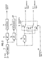
- Fig. 2 a simplified structure of a reproducing system associated with the recording system
- Fig. 3 the operation of the simultaneity switch shown in Fig. 2 is shown together with associated signals in Fig. 3 for reference.
- Figs. 1, and 3 will be briefly described before describing the present invention in detail.
- the magnetic recording system shown in Figure 1 includes an input terminal 1 of a luminance signal Y, an input terminal 2 of one of two color signals, for example, a color difference signal R-Y, an input terminal 3 of the other color signal, for example, a color difference signal B-Y, an FM modulator 4 using a main carrier having a frequency of about 7 MHz, another FM modulator 5 using a sub-carrier having a frequency of 1.2 MHz, another FM modulator6 using a sub-carrier having a frequency of 1.3 MHz, a line sequential switch 7, an adder circuit 8, a recording amplifier 9, a recording head 10, and an input terminal 11 of a switch control signal.
- the switch control signal is an on-off signal which is produced on the basis of, for example, a horizontal drive signal (or a so-called HD pulse) appearing at the start point of each horizontal scanning period (1H) and which rises to its high level and falls to its low level at a time interval of 1 H.
- the switch control signal is a 1/2H signal, where fH isthe horizontal scanning frequncy.
- the reproducing system includes a reproducing head 12, a head amplifier 13, a high-pass filter 14 for separating an FM luminance signal, an FM demodulator 15, a lowpass filter 16 for separating an FM line sequential color difference signal, another FM demodulator 17, a 1H delay line 18, a simultaneity switch 19, and an input terminal 20 of an identification signal ID.
- the color difference signals R-Y and B ⁇ Y in the demodulated line sequential color difference signal LSS are repeated in the order shown in Fig. 3(a), and the potential VH of the color difference signal B-Y in the horizontal blanking period HBLK B -y is higher than the potential V L of the color difference signal R-Y in the horizontal blanking period HBLK R ⁇ Y .
- the level of the identification signal ID changes in a relation corresponding to the repeated color difference signals R-Y and B-Y, that is, between "1" and "0" as, for example, shown in Fig. 3(b).
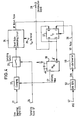
- the discrimination circuit includes an input terminal 21 of a demodulated line sequential color difference signal LSS, a clamping circuit 22, a sampling switch 23, an input terminal 24 of a sampling pulse signal SP, a reset pulse generating circuit 25, and a terminal 26 of a reference voltage Vref.
- Pulses, for example, HD pulses 28 are applied at a time interval of 1H to a frequency divider circuit 27 which is in the form of a flip-flop circuit F/F.
- An identification signal ID appears at an output terminal 29, and a clamping pulse generating circuit 30 is in the form of a monostable multivibrator M/M.
- the demodulated line sequential color difference signal LSS applied to the clamping circuit 22 starts from the color difference signal R ⁇ Y as shown in Fig. 5(a), and the potential V H of the color difference signal B-Y in the horizontal blanking period is higher than the potential V L of the color difference signal R-Y in the horizontal blanking period as also shown in Fig. 5(a).
- an HD pulse 28 appearing in each of the horizontal blanking periods is applied to the frequency divider circuit 27 as shown in Fig. 5(b).
- a clamping pulse CP as shown in Fig. 5(a) appears from the terminal Q of the clamping pulse generating circuit 30 in the first horizontal blanking period HBLK,. Consequently the potential in the first horizontal blanking period HBLK 1 is necessarily set at a clamped potential Vcp.
- sampling pulses SP are applied at a time interval of 1 H as shown in Fig. 5(c).
- the potential level sampled by application of the first sampling pulse SP is the clamped potential Vcp as shown in Fig. 5(f).
- the reset pulse generating circuit 25 generates a reset pulse RP by directly comparing its input voltage with the reference voltage Vref.
- the reset pulse generating circuit 25 is designed to generate a reset pulse RP only when the following relation holds: Therefore, when the clamped potential Vcp is so set as to satisfy the relation no reset pulse RP is generated in the case of the first sampling. Consequently, even when a second HD pulse HD 2 is applied to the frequency divider circuit 27, the Q output merely falls to its low level, and no clamping pulse is generated.
- the potential V H of the color difference signal B-Y 2 is higher than the potential Vcp clamped in the first horizontal blanking period HBLK,, due to the fact that the potential V H of the color difference signal B-Y in the horizontal blanking period is higher than the potential V L of the color difference signal R-Y in the horizontal blanking period as described above, and that the potential V L of the first color difference signal R-Y 1 is clamped atthe potential Vcp in the first horizontal blanking period HBLK 1 .
- the level sampled by application of a second sampling pulse SP 2 is thus, when the reference voltage Vref applied to the reset pulse generating circuit 25 is set so as to satisfy the relation a reset pulse RP as shown in Fig.
- the identification signal ID corresponds accurately to the line sequential color difference signal after the period of 2H counted from the time of end of the dropout.
- the HD pulse signal is provided by, for example, passing a composite video signal NTSC, which is a standard signal in the NTSC system, through a synchronizing signal separating circuit 58 and then through a horizontal scanning period rate conversion circuit (referred to hereinafter as an H-rate conversion circuit) 59.
- the synchronizing signal separating circuit 58 separates the horizontal synchronizing signal SYN from the composite video signal NTSC.
- the H-rate conversion circuit 59 extracts pulses appearing at a time interval of 1H, that is, so-called HD pulses in this embodiment, in response to the application of the output pulse signal from the synchronizing signal separating circuit 58.
- the H-rate conversion circuit 59 includes the combination of a flip-flop circuit 59a and a one-shot multivibrator 59b as shown, for example, in Fig. 6.
- Figs. 7(a) to 7(d) show operating waveforms appearing at various parts of the H-rate conversion circuit 59, Fig. 6.
- the operation of the H-rate conversion circuit 59 will be described with reference to Figs. 7(a) to 7(d).
- the horizontal synchronizing signal SYN which is the output pulse signal of the synchronizing signal separating circuit 58, as shown in Fig. 7(a) is applied to the input terminal C of the flip-flop circuit 59a.
- an output of "high" level as shown in Fig. 7(b) appears at the output terminal Q of the flip-flop circuit 59a.
- the reset terminal R is connected to output terminal Q through a resistor R i , the voltage at the reset terminal R increases gradually until it attains the reset voltage level after lapse of a predetermined time setting T, determined by the time constant of the combination of the resistor R, and a capacitor C 1 , as shown in Fig. 7(c).
- T a predetermined time setting
- the flip-flop circuit 59a is reset, and an output of "low" level appears at the output terminal Q.
- the capacitor C discharges through a diode D 1 , and the reset terminal R is restored to its original state.
- the output pulse signal of the synchronizing signal separating circuit 58 may include a noise pulse P, between the synchronizing pulses Ps, and P S2 of the horizontal synchronizing signal SYN.
- Such an unnecessary noise pulse P 1 which is attributable to a dropout or the like is removed in the H-rate conversion circuit 59. That is, when the time setting T 1 is selected to be slightly shorter than one horizontal scanning period 1 H, application of the noise pulse P 1 would not change the state of the output terminal Q of the flip-flop circuit 59a.
- the HD pulse signal generated from the output terminal Q of the multivibrator 59b is completely synchronized with the horizontal synchronizing signal SYN without being adversely affected by the noise and includes pulses rising to their "high" level at the time interval of 1H.
- the noise pulse P 1 will be applied to the frequency divider circuit 27 resulting in undesirable change-over of the simultaneity switch 19 at an improper position such as at a position midway of change-over between the color difference signals in the line sequential color difference signal LSS.
- the flip-flop circuit 59a in the H-rate conversion circuit 59 may be replaced by a non-retriggerable one-shot multivibrator.
- the reset pulse generating circuit 25 generates a reset pulse when the relation (1) holds as a result of direct comparison between the sampled input voltage and the reference voltage Vref. Therefore, the relations (2) and (3) must hold.
- the relation (1) providing the condition for generation of the reset pulse may be replaced by the following relation:
- the following relations may be set: when the above relations are set, the relation between the Q output of the frequency divider circuit 27 and the kind of the color difference signal is merely inverted from the previous case. Also, even when the relative levels of the potentials in the individual horizontal blanking periods are inverted, the relation between the Q output of the frequency divider circuit 27 and the kind of the color difference signal is merely inverted.
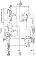
- the direct comparison between the sampled voltage and the reference voltage Vref is not necessarily required. Since an amplifier or the like is usually inserted in the system, it is more frequent that a voltage or current proportional to the sampled value is compared with the reference value. Such an embodiment of the present invention will be described with reference to Figs. 8 and 9.
- the clamping pulse CP is required to appear in the horizontal blanking period. Therefore, the clamping pulse generating circuit 30 may be arranged to be triggered in synchronism with the falling timing of the Q output of the frequency divider circuit 27. Also, the clamping pulse generating circuit 30 may be triggered in response to the Q output of the frequency divider circuit 27 in lieu of the Q output. Further, the identification signal ID may be generated from the terminal Q of the frequency divider circuit 27.
- a differential amplifier 31, a change-over switch 32, a constant current circuit 33, a current mirror circuit 34, a comparator 35 and a current-detecting resistor R constitute the reset pulse generating circuit 25.
- the other elements and symbols are the same as those incorporated and used in the circuit shown in Fig. 4.
- the operation of the embodiment shown in Fig. 8 will be described with reference to Figs. 9(a) to 9(h).
- Figs. 9(a) to 9(h) are compared with Figs. 5(a) to 5(h)
- Figs. 9(f) differs from that shown in Fig. 5(f).
- Figs. 9(f) differs from that shown in Fig. 5(f).
- Figs. 9(f) differs from that shown in Fig. 5(f).
- Figs. 9(f) differs from that
- the output of the differential amplifier 31 is applied to one of the contacts or the contact A of the change-over switch 32 and passes through the switch 32 to be applied to the current mirror circuit 34 during the sampling period only.
- the constant current circuit 33 is connected to the other contact B of the change-over switch 32 so that the constant current circuit 33 can be connected to the current mirror circuit 34 except for said sampling period.
- the terminal voltage E R of the resistor R connected to the output of the current mirror circuit 34 is applied to one of the input terminals of the comparator 35 to be compared with the reference voltage Vref applied to the other input terminal.
- the comparator 35 generates a reset pulse RP when the terminal voltage E R of the resistor R is lower than the reference voltage Vref.
- the bias voltage Eb and the reference voltage Vref are preferably that the terminal voltage E R of the resistor R is not substantially reduced and is sufficiently higher than the reference voltage Vref when the potential of the color difference signal in the first horizontal blanking period HBLK, is clamped by application of a first clamping pulse CP 1 and then sampled by application of a first sampling pulse SP 1 .
- the voltages Eb and Vref are so selected, no reset pulse appears in the first horizontal blanking period HBLK,, and, consequently, application of a second HD pulse HD 2 to the frequency divider circuit 27 would not produce any clamping pulse.
- the bias voltage Eb and the reference voltage Vref are further selected so that the output current of the differential amplifier 31 is greatly reduced and the terminal voltage E R of the resistor R becomes sufficiently lower than the reference voltage Vref when the voltage sampled by application of a second sampling pulse SP 2 is applied to the differential amplifier 31 in the second horizontal blanking period HBLK 2 .
- a reset pulse RP appears at the timing of the second sampling pulse SP 2 , and the potential in the second horizontal blanking period HBLK 2 is clamped.
- a third HD pulse HD 3 is applied to the frequency divider circuit 27, the Q output falls to its "low" level, and no clamping occurs.
- the potential in the third horizontal blanking period HBLK 3 is no reset pulse appears in this period.
- Application of a fourth HD pulse HD 4 to the frequency divider circuit 27 in the fourth horizontal blanking period HBLK 4 clamps also the potential, and no reset pulse appears similarly in this period.
- the current mirror circuit 34 is incorporated for the purpose of widening the dynamic range and is fundamentally unnecessary.
- the HD pulse signal is provided by the output signal of the H-rate conversion circuit 59.
- Fig. 10 shows in further detail the structure of the circuit shown in Fig. 8.
- transistors 36, 41 and a capacitor 48 constitute the clamping circuit 22.
- a transistor 39 corresponds to the sampling switch 23, and the combination of transistors 39 and 40 turned on/off and off/on respectively, corresponds to the change-over switch 32.
- the combination of transistors 41 and 42 constitutes the differential amplifier 31, and the combination of transistors 44 and 45 constitutes the current mirror circuit 34.
- Three resistors 46, 47 and 38 are provided to apply a suitable bias voltage Eb to the differential amplifier 31.
- the constant current circuit 33 supplies a constant current of 2mA
- the current-detecting resistor R has a resistance value of 2kQ
- the terminal voltage E R of this resistor R which is normally 4V, drops to 2V when the second sampling pulse SP 2 is applied.
- a capacitor 48 is provided for the purpose of DC regeneration.
- the sampling pulse signal SP may be generated with the timing inverse relative to the generation timing of the clamping pulse signal CP from the clamping pulse generating circuit 30. For example, when the clamping pulse signal CP is generated at the rising timing of the output signal of the frequency divider circuit 27, the sampling pulse signal SP may be generated at the falling timing of the same signal.
- the discrimination circuit includes an input terminal 21 of a line sequential color difference signal LSS, a clamping circuit 22, a sampling switch 23, a reset pulse generating circuit 25, a frequency divider circuit 27, an output terminal 29 of an identification signal ID, a clamping pulse generating circuit 30, and a sampling pulse generating circuit 49.
- the clamping pulse generating circuit 30 employs a monostable multivibrator triggered at the rising timing of the Q output of the frequency divider circuit 27, while the sampling pulse generating circuit 49 employs a monostable multivibrator triggered at the falling timing of the Q output of the frequency divider circuit 27. It is apparent that a monostable multivibrator triggered at the rsing timing of the Q output of the frequency divider circuit 27 can be equivalently employed in the sampling pulse generating circuit 49.
- the pulse width of the sampling pulse SP must not be large enough to exceed the horizontal blanking period.
- the output of the sampling switch 23 is applied to a comparator 35 in the reset pulse generating circuit 25.
- Figs. 12(a) to 12(h) show operating waveforms appearing at various parts of Fig. 11.
- the potential in the horizontal blanking period immediately after the horizontal blanking period in which the potential is first clamped is directly or indirectly compared with a reference value for discriminating the kind of the color difference signal.
- This method has such an advantage that clamping of the potential in the horizontal blanking period immediately before the discrimination of the kind of the color difference signal can effect quite accurate discrimination of the color difference signal independently of its picture pattern. It is needless to mention that any substantial delay of the discrimination of the kind of the color difference signal would not occur when compared to the method using bandpass filters and discriminating the color difference signal on the basis of the frequency difference, since the potential in the horizontal blanking period is utilized for discrimination.
- the discrimination circuit includes an input terminal 21 of a line sequential color difference signal LSS, two sample-hold circuits 50, 51, a frequency divider circuit 52 dividing the frequency of its input pulse signal by the factor of 2, two sampling pulse generating circuits 53, 54, a comparator circuit 55, and an Ex-OR gate 56.
- Each of the two sample-hold circuits 50 and 51 has a holding time of 2H.
- the frequency divider circuit 52 need not have any reset function and acts to merely divide the frequency of its input by the factor of 2.
- the two sampling pulse generating circuits 53 and 54 generate sampling pulses SPa and SPb alternately at a time interval of 1 H in individual horizontal blanking periods, respectively.
- these circuits 53 and 54 include monostable multivibrators connected to the output terminal Q of the frequency divider circuit 52 to be triggered respectively by the leading and trailing edges of the Q output of the frequency divider circuit 52.
- the line sequential color difference signal LSS and the Q output of the frequency divider circuit 52 have a relation as shown in Figs. 14(a) and 14(b). Then, the two sampling pulses SPa and SPb are generated in relation to the line sequential color difference signal LSS as shown in Figs. 14(c) and 14(d) respectively.
- the potential V L of the color difference signal R-Y is lower than the potential V H of the color difference signal B-Y.
- the Q output, instead of the Q output, of the frequency divider circuit 52 is applied to the Ex-OR gate 56 or also to the sampling pulse generating circuits 53 and 54.
- the output signal of an H-rate conversion circut 59 provides the HD pulse signal as in the case of the embodiment shown in Fig. 4.
- the identification signal is produced on the basis of the difference between the potentials in the adjacent horizontal blanking periods of a demodulated line sequential color difference signal. Therefore a delay, if any, of the discrimination timing can be substantially ignored when compared to the SECAM system using narrow-bandpass filters, and the color signals can be accurately discriminated without delay.
- the horizontal scanning period rate conversion circuit the H-rate conversion circuit
- a pulse signal which is synchronous with the horizontal synchronizing signal and includes pulses appearing accurately at the time interval of one horizontal scanning period is based on for effecting the desired accurate discrimination, so that the discrimination can be reliably effected at the desired position. That is, the discriminating operation can be effected at the predetermined position since, even when an unnecessary pulse attributable to, for example, dropout or noise may appear between the pulses of the horizontal synchronizing signal, the adverse effect of such a pulse can be easily removed.
Landscapes
- Engineering & Computer Science (AREA)
- Multimedia (AREA)
- Signal Processing (AREA)
- Processing Of Color Television Signals (AREA)
- Color Television Systems (AREA)
Claims (5)
Applications Claiming Priority (4)
| Application Number | Priority Date | Filing Date | Title |
|---|---|---|---|
| JP58192941A JPH0628466B2 (ja) | 1983-10-15 | 1983-10-15 | 信号再生装置 |
| JP192941/83 | 1983-10-15 | ||
| JP58241065A JPS60134590A (ja) | 1983-12-22 | 1983-12-22 | 線順次判別回路 |
| JP241065/83 | 1983-12-22 |
Publications (3)
| Publication Number | Publication Date |
|---|---|
| EP0139293A2 EP0139293A2 (de) | 1985-05-02 |
| EP0139293A3 EP0139293A3 (en) | 1986-09-10 |
| EP0139293B1 true EP0139293B1 (de) | 1990-06-27 |
Family
ID=26507608
Family Applications (1)
| Application Number | Title | Priority Date | Filing Date |
|---|---|---|---|
| EP84112419A Expired EP0139293B1 (de) | 1983-10-15 | 1984-10-15 | Diskriminatorschaltung für ein zeilensequentielles Signal |
Country Status (3)
| Country | Link |
|---|---|
| US (1) | US4623914A (de) |
| EP (1) | EP0139293B1 (de) |
| DE (1) | DE3482615D1 (de) |
Families Citing this family (7)
| Publication number | Priority date | Publication date | Assignee | Title |
|---|---|---|---|---|
| JPH0810947B2 (ja) * | 1985-05-24 | 1996-01-31 | キヤノン株式会社 | ビデオ信号処理装置 |
| JP2573925B2 (ja) * | 1985-07-16 | 1997-01-22 | 富士写真フイルム株式会社 | 画像ハ−ドコピ−作成装置 |
| JP2592868B2 (ja) * | 1987-11-18 | 1997-03-19 | キヤノン株式会社 | 線順次情報信号処理装置 |
| JP2786686B2 (ja) * | 1989-09-04 | 1998-08-13 | 株式会社東芝 | セカムカラー信号処理回路 |
| JP2589175Y2 (ja) * | 1990-01-12 | 1999-01-20 | 旭光学工業 株式会社 | 記録装置 |
| JP6273090B2 (ja) | 2009-08-24 | 2018-01-31 | アルベマール・ユーロプ・エスピーアールエル | 第6族金属、第8族金属及びリンを含む溶液及び触媒 |
| CN114355298B (zh) * | 2022-01-04 | 2023-08-18 | 中国电子科技集团公司第十研究所 | 一种雷达复合调制脉冲信号识别方法 |
Family Cites Families (9)
| Publication number | Priority date | Publication date | Assignee | Title |
|---|---|---|---|---|
| GB1188392A (en) * | 1966-07-19 | 1970-04-15 | Sony Corp | Television Signal Recording System |
| GB1566713A (en) | 1976-02-24 | 1980-05-08 | Rca Corp | Identification circuit |
| GB1536215A (en) * | 1976-07-05 | 1978-12-20 | Decca Ltd | Clamping circuits for television signals |
| FR2371111A1 (fr) | 1976-11-15 | 1978-06-09 | Rca Corp | Modulateur secam |
| US4191965A (en) | 1977-05-23 | 1980-03-04 | Tektronix, Inc. | Apparatus and method for testing color sequencing of secam color television signals |
| US4240102A (en) | 1978-03-16 | 1980-12-16 | Rca Corporation | Identification system for SECAM or SECAM/PAL color television receivers |
| JPS54159125A (en) | 1978-06-07 | 1979-12-15 | Sony Corp | Correction circuit |
| US4357623A (en) | 1981-04-24 | 1982-11-02 | Rca Corporation | SECAM Identification system |
| FR2551295B1 (fr) | 1983-08-24 | 1985-10-25 | Radiotechnique Compelec | Circuit d'identification de couleur secam |
-
1984
- 1984-10-12 US US06/660,325 patent/US4623914A/en not_active Expired - Lifetime
- 1984-10-15 DE DE8484112419T patent/DE3482615D1/de not_active Expired - Lifetime
- 1984-10-15 EP EP84112419A patent/EP0139293B1/de not_active Expired
Also Published As
| Publication number | Publication date |
|---|---|
| EP0139293A2 (de) | 1985-05-02 |
| EP0139293A3 (en) | 1986-09-10 |
| DE3482615D1 (de) | 1990-08-02 |
| US4623914A (en) | 1986-11-18 |
Similar Documents
| Publication | Publication Date | Title |
|---|---|---|
| EP0159871B1 (de) | Aufnahme- und Wiedergabevorrichtung für Teletextsignale | |
| EP0289046B1 (de) | Vorrichtung zum Ermitteln von Zeitbasisschwankungen für einen Videobandrecorder | |
| EP0442478B1 (de) | Vorrichtung zur Durchführung einer y/c-Trennung | |
| EP0139293B1 (de) | Diskriminatorschaltung für ein zeilensequentielles Signal | |
| EP0153027A2 (de) | Aufzeichnungs- und Wiedergabesystem für Farb-Video-Signale | |
| US5081537A (en) | Color image information inserting circuit for video signal recording and reproducing system | |
| US4980779A (en) | Information signal recording and/or reproducing apparatus for correcting time variations | |
| JPH0748873B2 (ja) | 磁気記録再生装置 | |
| US5598274A (en) | Image signal recording and reproducing system | |
| HK113396A (en) | Device for recording and/or reproducing picture signals | |
| JPS587117B2 (ja) | イロシンゴウシヨリカイロ | |
| US5166803A (en) | Image signal recording and reproducing system | |
| US4133002A (en) | Pal identification circuit | |
| JPH0779456B2 (ja) | 磁気記録再生装置 | |
| EP0169013B1 (de) | Vorrichtung zum Aufzeichnen und Wiedergeben eines Videosignals | |
| EP0311117A2 (de) | Videobandrecorder mit einer Pilotsignal-Steuerfunktion zum Auswählen von Luminanzsignal-Filtermerkmalen bei der Wiedergabe | |
| JPH0628466B2 (ja) | 信号再生装置 | |
| JPH0195692A (ja) | 磁気記録再生装置 | |
| JPS60134590A (ja) | 線順次判別回路 | |
| JPH04245892A (ja) | クランプ装置 | |
| JPH0346630Y2 (de) | ||
| JPH0526868Y2 (de) | ||
| JP2524521B2 (ja) | 磁気記録再生装置 | |
| JPS6261490A (ja) | クランプ回路 | |
| JPH0346631Y2 (de) |
Legal Events
| Date | Code | Title | Description |
|---|---|---|---|
| PUAI | Public reference made under article 153(3) epc to a published international application that has entered the european phase |
Free format text: ORIGINAL CODE: 0009012 |
|
| AK | Designated contracting states |
Designated state(s): DE FR GB NL |
|
| PUAL | Search report despatched |
Free format text: ORIGINAL CODE: 0009013 |
|
| AK | Designated contracting states |
Kind code of ref document: A3 Designated state(s): DE FR GB NL |
|
| 17P | Request for examination filed |
Effective date: 19870310 |
|
| 17Q | First examination report despatched |
Effective date: 19881215 |
|
| GRAA | (expected) grant |
Free format text: ORIGINAL CODE: 0009210 |
|
| AK | Designated contracting states |
Kind code of ref document: B1 Designated state(s): DE FR GB NL |
|
| REF | Corresponds to: |
Ref document number: 3482615 Country of ref document: DE Date of ref document: 19900802 |
|
| ET | Fr: translation filed | ||
| PLBE | No opposition filed within time limit |
Free format text: ORIGINAL CODE: 0009261 |
|
| STAA | Information on the status of an ep patent application or granted ep patent |
Free format text: STATUS: NO OPPOSITION FILED WITHIN TIME LIMIT |
|
| 26N | No opposition filed | ||
| REG | Reference to a national code |
Ref country code: GB Ref legal event code: IF02 |
|
| PGFP | Annual fee paid to national office [announced via postgrant information from national office to epo] |
Ref country code: GB Payment date: 20020924 Year of fee payment: 19 |
|
| PGFP | Annual fee paid to national office [announced via postgrant information from national office to epo] |
Ref country code: NL Payment date: 20021017 Year of fee payment: 19 Ref country code: FR Payment date: 20021017 Year of fee payment: 19 |
|
| PGFP | Annual fee paid to national office [announced via postgrant information from national office to epo] |
Ref country code: DE Payment date: 20021227 Year of fee payment: 19 |
|
| PG25 | Lapsed in a contracting state [announced via postgrant information from national office to epo] |
Ref country code: GB Free format text: LAPSE BECAUSE OF NON-PAYMENT OF DUE FEES Effective date: 20031015 |
|
| PG25 | Lapsed in a contracting state [announced via postgrant information from national office to epo] |
Ref country code: NL Free format text: LAPSE BECAUSE OF NON-PAYMENT OF DUE FEES Effective date: 20040501 Ref country code: DE Free format text: LAPSE BECAUSE OF NON-PAYMENT OF DUE FEES Effective date: 20040501 |
|
| GBPC | Gb: european patent ceased through non-payment of renewal fee |
Effective date: 20031015 |
|
| PG25 | Lapsed in a contracting state [announced via postgrant information from national office to epo] |
Ref country code: FR Free format text: LAPSE BECAUSE OF NON-PAYMENT OF DUE FEES Effective date: 20040630 |
|
| NLV4 | Nl: lapsed or anulled due to non-payment of the annual fee |
Effective date: 20040501 |
|
| REG | Reference to a national code |
Ref country code: FR Ref legal event code: ST |