EP0139104B1 - Kombinationsmessgerät - Google Patents
Kombinationsmessgerät Download PDFInfo
- Publication number
- EP0139104B1 EP0139104B1 EP84108427A EP84108427A EP0139104B1 EP 0139104 B1 EP0139104 B1 EP 0139104B1 EP 84108427 A EP84108427 A EP 84108427A EP 84108427 A EP84108427 A EP 84108427A EP 0139104 B1 EP0139104 B1 EP 0139104B1
- Authority
- EP
- European Patent Office
- Prior art keywords
- measuring
- hoppers
- pool
- rotary
- links
- Prior art date
- Legal status (The legal status is an assumption and is not a legal conclusion. Google has not performed a legal analysis and makes no representation as to the accuracy of the status listed.)
- Expired
Links
Images


Classifications
-
- G—PHYSICS
- G01—MEASURING; TESTING
- G01G—WEIGHING
- G01G19/00—Weighing apparatus or methods adapted for special purposes not provided for in the preceding groups
- G01G19/387—Weighing apparatus or methods adapted for special purposes not provided for in the preceding groups for combinatorial weighing, i.e. selecting a combination of articles whose total weight or number is closest to a desired value
- G01G19/393—Weighing apparatus or methods adapted for special purposes not provided for in the preceding groups for combinatorial weighing, i.e. selecting a combination of articles whose total weight or number is closest to a desired value using two or more weighing units
-
- G—PHYSICS
- G01—MEASURING; TESTING
- G01G—WEIGHING
- G01G13/00—Weighing apparatus with automatic feed or discharge for weighing-out batches of material
- G01G13/02—Means for automatically loading weigh pans or other receptacles, e.g. disposable containers, under control of the weighing mechanism
- G01G13/022—Material feeding devices
- G01G13/024—Material feeding devices by gravity
-
- G—PHYSICS
- G01—MEASURING; TESTING
- G01G—WEIGHING
- G01G13/00—Weighing apparatus with automatic feed or discharge for weighing-out batches of material
- G01G13/02—Means for automatically loading weigh pans or other receptacles, e.g. disposable containers, under control of the weighing mechanism
- G01G13/04—Means for automatically loading weigh pans or other receptacles, e.g. disposable containers, under control of the weighing mechanism involving dribble-feed means controlled by the weighing mechanism to top up the receptacle to the target weight
- G01G13/06—Means for automatically loading weigh pans or other receptacles, e.g. disposable containers, under control of the weighing mechanism involving dribble-feed means controlled by the weighing mechanism to top up the receptacle to the target weight wherein the main feed is effected by gravity from a hopper or chute
Definitions
- the invention relates to the automatic measuring techniques for accurately measuring the weight of commercial products of granular foodstuffs, such as beans, before transferring them to a packaging process. It is especially related to a combination measuring apparatus according to the pre-characterizing portion of claim 1.
- the objects being measured are dispersed within a suitable dispersion range, each object is then measured and the separate measured values thus obtained by the dispersion measurement are combined and calculated in accordance with probability and statistical logic so that the combined weight becomes a "plus minimum over quantity".
- the objects thus measured are packaged in individual packages.
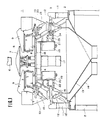
- An inner frame 3 is provided above a frame 2 of a combination measuring apparatus 1, and an upper frame 4 is provided above the inner frame 3.
- a dispersion table 7 is positioned on this upper frame 4, concentrically with a feed port 6 for the objects being measured, in such a manner that the dispersion table 7 can rock and reciprocate through a set angle.
- Troughs 9 are arranged in the radial direction around the dispersion table 7, on electromagnetic vibrators 8.
- a pool hopper 10 and a measuring hopper 12 are provided for each trough 9 in a circumferential arrangement about the upper frame 4.
- Each measuring hopper 12 is positioned below the corresponding pool hopper 10, and is supported by a weight detector 11 such as a load cell provided on the frame.
- a weight detector 11 such as a load cell provided on the frame.
- One each of a pool hopper 10 and a measuring hopper 12 form one unit, and 14 units, for example, are positioned around the upper frame 4.
- the objects being measured, such as beans, are charged from the feed port 6, are dispersed by the dispersion table 7, are sequentially fed by the troughs 9 to each pool hopper 10 to the corresponding measuring hopper 12, and are measured by the weight detector 11.
- a combination of "plus minimum over quantities" from among these measuring hoppers 12 is selected by a micro-computer (not shown), and the objects being measured are charged by the frame 2 into gathering chutes 13, 14 positioned therebelow and are thereafter transferred to the subsequent packaging step.
- covers 15, 16, 16' of the pool and measuring hoppers 10 and 12 must be opended and closed.
- the operating mechanisms for these covers are constructed as follows.
- Driving devices 19 such as cam mechanisms are arranged around a motor 17 so as to face each of the pool and measuring hoppers 12, and are driven by the motor 17 via a gear mechanism 18.
- Push rods 20, 21, 22 move back and forth in the radial direction in response to the operation of the corresponding driving devices, thereby opening and closing cover-operating links 23, 24, 25 for the covers 15, 16, 16'.
- EP-A-0072707 discloses a combination measuring apparatus, the driving device of which is disposed inside a circle defined by measuring hoppers disposed correspondent to distribution supply devices arranged radially around a distribution table.
- the driving device is adapted to selectively open the hoppers to make the hoppers constituting the selected combination, which provides a total weight most closely approximating a preset target weight.
- a packaging apparatus is connected directly to the lower parts of gathering chutes of the combination measuring apparatus and the selected hoppers are opened thereby discharging the measured objects into the gathering chutes clogging of the measured objects or the articles being packaged, that is, a phenomenom called "bridging" of the articles, will be induced by the instantaneous discharge of large quantities of articles.
- This phenomenon is not very severe when the quantities are small, but when the quantities are relatively large, the vortex motion of the descending articles will make them jump, even if bridging does not occur, and, in the worst case, vigorous interference will occur between the articles which will damage them.
- time-difference discharge is effected. This is accomplished by providing time differences between the opening of the covers of the measuring hoppers of the predetermined combination.
- DE-B-2 552 236 shows a sluice for bulk material which is opened and closed by a mechanism comprising rods, to which reciprocating movement is transmitted by a rotating cam plate.
- Reference numeral 1' represents the combination measuring apparatus constituting the gist of the present application, its structure is schematically illustrated in Figure 2 (in which only a section of the right half thereof is illustrated for the purpose of description, but the left half has the same construction, and each mechanism is equidistantly arranged therein).
- Upper and lower frames 4 and 4' are provided on an inner frame 3 on top of a frame 2, and a dispersion table 7 is positioned concentrically with the center of the upper surface of the upper frame 4 immediately below a charging port 6 in an upper portion, on a heretofore known electromagnetic oscillator 5, in such a fashion that the dispersion table 7 can reciprocate in the circumferential direction through a set angle.
- a predetermined number, 14 for example, of troughs 9 are radially and equidistantly arranged around the dispersion table, on electromagnetic oscillators 8.
- Pool hoppers 10 are arranged equidistantly in the circumferential direction on brackets 26 positioned around the upper frame 4 so as to correspond and to be connected to the troughs 9 by hooks, not shown, in the same way as in the prior art apparatus, so that tne hoppers 10 can be attached by a simple operation.
- Corresponding measuring hoppers 12 are positioned below the pool hoppers on brackets 27, so that they can mesh with, and be attached to, load cells 11 (described later) in the radial direction, by a simple operation.
- a cover 15 is pivotally supported about a base end thereof to the discharge port at the lower end of each pool hopper 10, and is normally biased in the closing direction by a tension spring 28 via a cover-operating link 23 connected to the spring 28.
- a pair of covers 16, 16' of each measuring hopper 12 are normally biased in the closing direction by a tension spring 29 via cover-operating links 24, 25, respectively.
- a fork-shaped hook 30 is formed at the end of each of the covet-operating links 23, 24 and 25.
- Two gathering chutes 13, 14 are provided below the measuring hoppers 12, and are connected to a subsequent packaging process (not shown).
- a cover plate 31 is provided around the entire circumference between the upper and lower frames 4 and 4', and 14 units, each consisting of one pool hopper 10 and one measuring hopper 12, are equidistantly arranged around the entire circumference, outside the cover plate 31.
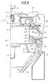
- a motor 17 equipped with a reduction gear is mounted below the central part of the lower frame 4' so that a pinion thereof, not shown, on the output shaft of the motor drives a driving sprocket wheel 32 by a gear mechanism, not shown, while the driving sprocket wheel 32 in turn drives a pair of follower sprocket wheels 34 by a chain 33.
- the pair of follower sprocket wheels 34 each rotate oval grooved cams 35, 35' mounted on an intermediate frame 4" on brackets, not shown, through a predetermined distance.
- a rocking shaft 37 is supported between the upper and intermediate frames 4 and 4" by a bearing 36 so as to be capable of rocking reely, and an arm 38 is pivotally supported at an intermediate part of the rocking shaft 37 so as to be capable of rocking relative to the rocking shaft 37, but not move vertically.
- a cam follower 39 which is pivotally supported at the end of the arm 38 fits into the cam grooves of the oval grooved cam 35 so that the arm 38 is rocked by the rotation of the cam.
- a rotary link 40 is attached to the upper surface of the arm 38 and another rotary link 40' is attached to the rocking shaft 37 above the arm 38.
- the rotary links 40, 40' support around them pivotally the base ends of connecting rods 41 and 41', corresponding to the pool hoppers 10 and the measuring hoppers 12, respectively, on pins 42.
- Sub-frames 43 are attached to the lower frame 4' so as to face each of the measuring hoppers 12 in the radial direction, and sliders 45 that can move back and forth in the radial direction are positioned on pairs of guide bars 44 arranged in the radial direction on top of the sub-frames 43.
- the end of each connecting rod 41 is pivotally supported by the inner end portion of a slider 45 on a pin 46, so as to be capable of rocking and rotating relative thereto.
- Sub-frames 43' of substantially U-shaped section in the longitudinal direction are arranged under the upper frame 4 so as to face the pool hoppers 10, and sliders 45' are positioned on guide bars 44' which are mounted on the undersides of the sub-frames 43', so as to be capable of moving back and forth in the radial direction.
- the end of each connecting rod 41' is supported at the inner end of a slider 45' in such a manner that it is capable of rocking and rotating relative thereto.
- Each of the sub-frames 43 mounted on the lower frame 4' has a heretofore known load cell 11 acting as a weight detector mounted on one side surface thereof in the radial direction from the measuring hopper 12, and the bracket 27 is fitted onto the outer end of the load cell 11 so that the measuring hopper can be engaged and anchored by a simple operation on pins 47, 48.
- the weight of the objects being measured is detected by the load cell 11 and is input to a microcomputer, not shown.
- the load cells 11 of this embodiment are positioned further inward than the measuring hoppers 12 and, moreover, in the radial direction, so that the space within the circle of measuring hoppers 12 can be utilized efficiently.
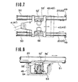
- Pairs of push rods 20 are mounted on the subframes 43 so as to be capable of moving back and forth in the radial direction, and two rollers 49 are provided outside and to the sides of the ends of each pair of push rods so as to face two fork-shaped hooks 30 on the cover-operating links 24, 25 that open and close the two covers 16, 16' of each measuring hopper 12.
- a compression spring 50 is interposed between a flange portion at the inner end of each push rod and the sub-frame 43 so as to urge the rod in the backward direction.
- Each push rod 20 is inserted through the corresponding slider 45 and can move back and forth relative to the slider.
- a flat surface 51 is formed on the inner side surface of each of the pair of push rods 20 within a predetermined stroke range and a rack 52 is defined on a predetermined part of this flat surface 51.
- Solenoids 53 are provided on both side surfaces of the sliders 45 and tips 55 thereof are inwardly urged by compression springs 54.
- Racks 56 corresponding to the racks 52 on the push rods 20 are formed on the outer surface of each of the tips 55, so that when a current is applied to a solenoid 53 by a controller (not shown) at a predetermined timing, the tip 55 moves forward against the force of the compression spring 54 so that the rack 56 meshes with the rack 52 of the slider 45, thereby generating a clutch function such that the slider 45 and the push rods 20 move integrally back and forth in the radial direction with respect to the sub-frame 43, and engage with or disengage from each hook 30 of the cover-operating link 25 of the measuring hopper 12 to open or close the cover.
- the slider 45' has exactly the same operation as the mechanism of Figures 5 and 6, so that engagement and disengagement of a roller 49 at the end of the push rod 20' with and from the fork-shaped hook 30 of the cover-operating link 23 of the single cover 15 of the pool hopper 10, and the opening and closing of the cover 15, are also exactly the same as those of Figures 5 and 6.
- the objects being measured are distributed into the troughs 9 around the dispersion table 7 by the table 7 that is vibrated and rotated in the circumferential direction through the set angle by the electromagnetic vibrator 8.
- the objects are distributed in quantities that vary to a certain extent.
- the objects dispersed into each trough 9 are then transferred into the corresponding pool hoppers 10 by being vibrated by the electromagnetic vibrator 5.
- the push rod During its outward movement, the push rod enters the fork-shaped hook 30 of the cover-operating link 23 of the pool hopper 10 and opens the cover 15 in its opening direction against the force of the tension spring 28, so that the objects being measured that had been held are charged into the measuring hopper 12 therebelow.
- the solenoid 53 is released by the timer operation of a controller and its tip 55 is moved inward by the compression spring 54 so that the racks 52 and 56 disengage from each other, the push rod 20' is moved back inward by the force of the compression spring 50 to its original position, and the cover 15 of the pool hopper 10 is forced to its closing position by the tension spring 28.
- the weight of the objects being measured that are thus charged into the measuring hopper 12 is immediately detected by the load cell 11 fitted to the sub-frame 43, and the detected weight is input to the microcomputer, not shown. All the weights from all the measuring hoppers 12 are compared and calculated to determine which measuring hoppers 12 provide the most suitable combination for the set weight, using the plus minimum over quantity, and to decide into which gathering chute 13 or 14 the objects are to be discharged.
- the covers 16 or 16' of the measuring hoppers 12 that have been selected for the combination and have thus been emptied by the discharge of the objects being measured, are returned to their original state by the tension springs 29, the covers is of only the pool hoppers 10 corresponding to those measuring hoppers 12 operate upon receipt of a signal from the controller (not shown), and the objects being measured are again charged into the measuring hoppers 12. The fresh objects being measured are also supplied to the pool hoppers 10. As the processes described above are repeated, the articles which are to be packaged in single packages containing the possible plus minimum over quantity are sequentially and alternately discharged into the gathering chutes 13, 14 and are then transferred to the packaging step.
- the outer end of the tip 55' is made to be a flat surface 56' instead of the racks 52, 56 shown in Figures 5 and 6, and this flat surface 56' engages with and disengages from the corresponding flat groove 52' in each push rod 20 (20').
- the action and effect of this embodiment is substantially the same as that of the previous embodiment.
- the covers 16 are opened, and the measured objects are discharged into the gathering chutes 13, 14.
- the packaging apparatus is connected directly to the lower parts of the gathering chutes 13, 14 by shoulders, for example, clogging of the measured objects or the articles being packaged, that is, a phenomenon called "bridging" of the articles, will be induced by the instantaneous discharge of large quantities of articles. This phenomenon is not very severe when the quantities are small, but when the quantities are relatively large, the vortex motion of the descending articles will make them jump, even if bridging does not occur, and, in the worst case, vigorous interference will occur between the articles which will damage them.
- time-difference discharge To prevent this problem, a so-called "time-difference discharge” must be effected. This can be accomplished by providing time differences between the opening of the covers 16, 16' of the measuring hoppers 12 of the predetermined combination. In the embodiments described above, however, since the covers 16, 16' of the measuring hoppers 12 are opened and closed together at the same timing, the merit of time-difference discharge is hindered.
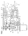
- Three oval, grooved cams 351, 352, 353 for three measuring hoppers and one oval cam 35' for a pool hopper are disposed in the circumferential direction at spacings of about 90°, linked to the motor 17 by four electromagnetic brakes 59 and gears 33', 34' which are connected to the motor 17 by electromagnetic clutches 60.
- the cams 351, 352, 353 and 35' are rotated at a predetermined timing by the electromagnetic clutches 60.
- a rotary link 40' which is the same as the rotary link of the embodiments described above is attached by a key to the upper part of the rocking shaft 37 which is pivotally inserted in the frame 4", and the base of the arm 38' pivotally supporting the cam follower 39' which meshes with the oval groove in the oval, grooved cam 35' is attached to the rocking shaft 37 below the rotary link 40', as shown in Figure 11.
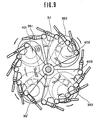
- Three bearing bosses 61, 62, 63 are each attached intermediate part of the rocking shaft 37 by roller-type radial bearings 58 and thrust bearings 68 in a vertical, arrangement, and three fan-shaped rotary links 401, 402, 403 of a similar shape which define fan-shaped spaces 57 of a small angle between them are arranged in the same horizontal plane, as shown in Figure 10.
- Arms 381', 382', 383' extend diagonal downward and integrally from the boss bearings 61, 62, 63, respectively, as shown in Figure 11, and cam followers 391, 392, 393 are pivotally supported at the ends of these arms, respectively.
- the cam followers mesh with the oval grooved cams 351, 352, 353, and rock around the rocking shaft 37. Accordingly, the fan-shaped rotary links 401, 402, 403 can rock independently around the rocking shaft 37 without any mutual interference.
- the rotary links rock independently of one another when the oval, grooved cams 351, 352, 353 are rotated independently of one another by the electromagnetic clutches 60 with the rotation of the motor 17, so that each connecting rod 41 can operate the slider 45 for each block independently in each fan-shaped rotary link 401, 402, 403.
- each fan-shaped rotary link 401, 402, 403 rocks independently, the fan-shaped spaces 57 defined between the rotary links become zero so that the rotary links do not interfere with one another.
- Figure 9 is a plan view showing Figures 10 and 11 superimposed.
- the opening and closing of the cover 16 of each measuring hopper 12 is controlled by at least three different timing differences due to the mutually-independent rocking motions of the rotry links 401,402,403 of each block.
- the electromagnetic clutches 60 of the fan-shaped rotary links 401, 402, 403 corresponding to the selected measuring hoppers 12 operate at time delays set by predetermined time delay control circuits, and rotate the oval, grooved cams 351, 352, 353.
- the arms 381', 382', 383' are operated with the same time delays by the cam followers, so that the fan-shaped rotary links 401, 402, 403 also rock with time delays, and each of the connecting rods 41 pivotally supported by each fan-shaped rotary link 401, 402, 403 also operates with the time delay of its rotary link, moving the sliders 45 back and forth. Since the solenoids 53 determined for the combination selection do not operate in the same way as in the embodiments described above, the racks 52 engage with the racks 56, and the covers 16, 16' of the selected measuring hoppers 12 are opened in the same way as in the embodiments described above.
- some of the predetermined number of measuring hoppers 12 given by the selection for example, three out of five measuring hoppers 12, perform a time-difference discharge with set time delays between them. For this reason, a large quantity of articles can be smoothly discharged without any clumping or interference within the gathering hoppers 13, 14, particularly at the neck portions thereof.
- weight detectors can be disposed between the subframes.
- the size of the combination measuring apparatus can be fundamentally reduced, particularly in the lateral direction, and its diameter and installation space requirements can be reduced. Since the apparatus can be made more compact than before, and the space within it can be efficiently utilized, the space requirements of the apparatus can be reduced and the apparatus will not hinder the operations of other apparatuses.
- the apparatus itself is compact, the operating distances of its internal links, gears, and the like are smaller, and vibration of the apparatus can be suppressed. Accordingly, the apparatus has an improved durability, reduced wear and problems, and its maintenance and inspection can be done easily.
- the efficiency of the apparatus is largely proportional to the flow quantity and flow speed, but since the apparatus is compact, the distance that the objects being measured flows through is short, and the performance, and thus the accuracy, of the apparatus can be markedly improved.
- the push rods for opening and closing the covers of a large number of pool hoppers and measuring hoppers positioned circumferentially around the center of the apparatus are radially connected to rotary links that operate in an interlocking arrangement by a driving device provided at the center of the space within the apparatus via connecting rods, so that an opening and closing mechanism for each pool hopper and measuring hopper can be controlled from the center, and the space within the apparatus can be utilized three-dimensionally. Accordingly, the internal space does not have local high density spots, but can be utilized uniformly. This eliminates the eccentric disposition of various high-density mechanisms and improves the freedom of design, enabling each mechanism to operate smoothly.
- each connecting rod gathers at the center, no design problem occurs because they are connected to rotary links.
- the end of each connecting rod is connected to a slider moving back and forth on a subframe corresponding to each pair of pool hopper and measuring hopper, and hence only a sub-frame provided with a slider and which has a simple structure is required to correspond to each pool hopper and measuring hopper. Hence, no design problem occurs, either, when designing each sub-frame and slider.
- a clutch is formed on each push rod at a peripheral portion some distance from the center and close to the sub-frame where larger design dimensions can be obtained. This clutch can control the forward and backward movement of the push rod with respect to the operating link for the cover of each pool hopper or measuring hopper.
- a weight detector such as a load cell for the measuring hopper which is conventionally positioned at an outer position, can be fitted radially for each sub-frame.
- the weight detectors can be fitted by utilizing the spaces between the measuring hoppers without raising any design problems.
- a weight detector can be positioned on the inner side of each measuring hopper, the outer dimensions of the combination measuring apparatus can be further reduced in the radial direction.
- the apparatus can be made compact, vibrations are suppressed which markedly improves the weight-detecting performance of the weight detectors for the measuring hoppers.
- the apparatus is made compact, the space within it can be utilized sufficiently and deficiently with a more uniform density, and this eliminates the necessity that each of the mechanical portions must be forced to be compact, so that they can be produced easily.
Landscapes
- Physics & Mathematics (AREA)
- General Physics & Mathematics (AREA)
- Weight Measurement For Supplying Or Discharging Of Specified Amounts Of Material (AREA)
Claims (5)
Applications Claiming Priority (2)
| Application Number | Priority Date | Filing Date | Title |
|---|---|---|---|
| JP58130277A JPS6022626A (ja) | 1983-07-19 | 1983-07-19 | 組合せ計量装置 |
| JP130277/83 | 1983-07-19 |
Publications (3)
| Publication Number | Publication Date |
|---|---|
| EP0139104A2 EP0139104A2 (de) | 1985-05-02 |
| EP0139104A3 EP0139104A3 (en) | 1986-03-19 |
| EP0139104B1 true EP0139104B1 (de) | 1988-12-14 |
Family
ID=15030455
Family Applications (1)
| Application Number | Title | Priority Date | Filing Date |
|---|---|---|---|
| EP84108427A Expired EP0139104B1 (de) | 1983-07-19 | 1984-07-17 | Kombinationsmessgerät |
Country Status (5)
| Country | Link |
|---|---|
| US (1) | US4606475A (de) |
| EP (1) | EP0139104B1 (de) |
| JP (1) | JPS6022626A (de) |
| CA (1) | CA1222499A (de) |
| DE (1) | DE3475650D1 (de) |
Families Citing this family (8)
| Publication number | Priority date | Publication date | Assignee | Title |
|---|---|---|---|---|
| US4676325A (en) * | 1985-05-10 | 1987-06-30 | Yamato Scale Company, Limited | Combination weighing method with two discharge paths and two target weights |
| JPH057553Y2 (de) * | 1985-09-02 | 1993-02-25 | ||
| US4720961A (en) * | 1986-01-13 | 1988-01-26 | Conagra, Inc. | Chicken sorting device |
| JPS6397828U (de) * | 1986-12-15 | 1988-06-24 | ||
| US5331792A (en) * | 1992-12-04 | 1994-07-26 | Kitchen Farms, Inc. | Packaging unit |
| IT1276686B1 (it) * | 1995-06-08 | 1997-11-03 | Simionato Spa | Insieme di cestelli di pesatura in una macchina confezionatrice |
| WO2000066983A1 (en) | 1999-05-03 | 2000-11-09 | Bilwinco A/S | A weighing machine |
| JP5133714B2 (ja) * | 2008-01-22 | 2013-01-30 | アンリツ産機システム株式会社 | 組合せ計量装置 |
Family Cites Families (10)
| Publication number | Priority date | Publication date | Assignee | Title |
|---|---|---|---|---|
| US3822032A (en) * | 1973-03-01 | 1974-07-02 | Pneumatic Scale Corp | Apparatus for filling containers including means responsive to both the weight and the height of the material dispensed |
| FR2271984A1 (en) * | 1974-05-20 | 1975-12-19 | Pneumatic Scale Corp | Food container filling machine - for granular or flaky foods has shut off system operated by both weight and volume detectors |
| US4142751A (en) * | 1977-12-08 | 1979-03-06 | Pullman Incorporated | Door locking mechanisms for hoppers |
| US4193465A (en) * | 1978-01-27 | 1980-03-18 | The Woodman Company, Inc. | Scale hopper door mechanism |
| AU541709B2 (en) * | 1981-08-18 | 1985-01-17 | K.K. Ishida Koki Seisakusho | Combinatorial weighing apparatus |
| JPS5847136U (ja) * | 1981-09-21 | 1983-03-30 | 株式会社石田衡器製作所 | 自動計量装置におけるホツパ−脱着装置 |
| JPS5852523A (ja) * | 1981-09-24 | 1983-03-28 | Ishida Scales Mfg Co Ltd | 自動計量装置 |
| JPS5972516U (ja) * | 1982-11-08 | 1984-05-17 | 株式会社石田衡器製作所 | 自動計量装置におけるホツパ開閉装置 |
| JPS59114075A (ja) * | 1982-12-21 | 1984-06-30 | Fuji Xerox Co Ltd | 感熱記録装置 |
| JPH022088A (ja) * | 1988-06-14 | 1990-01-08 | Casio Comput Co Ltd | 熱転写方法 |
-
1983
- 1983-07-19 JP JP58130277A patent/JPS6022626A/ja active Granted
-
1984
- 1984-07-10 US US06/630,580 patent/US4606475A/en not_active Expired - Fee Related
- 1984-07-16 CA CA000458960A patent/CA1222499A/en not_active Expired
- 1984-07-17 EP EP84108427A patent/EP0139104B1/de not_active Expired
- 1984-07-17 DE DE8484108427T patent/DE3475650D1/de not_active Expired
Also Published As
| Publication number | Publication date |
|---|---|
| EP0139104A3 (en) | 1986-03-19 |
| CA1222499A (en) | 1987-06-02 |
| JPH0477858B2 (de) | 1992-12-09 |
| EP0139104A2 (de) | 1985-05-02 |
| US4606475A (en) | 1986-08-19 |
| DE3475650D1 (en) | 1989-01-19 |
| JPS6022626A (ja) | 1985-02-05 |
Similar Documents
| Publication | Publication Date | Title |
|---|---|---|
| US4708215A (en) | Automatic weighing system | |
| US4206822A (en) | Apparatus for the exact weighing of material in lots of mixed-size pieces | |
| US4560015A (en) | Combinatorial weighing apparatus | |
| US5959258A (en) | Multiple hopper weighing and transfer system | |
| US4497385A (en) | Combinatorial weighing apparatus | |
| EP0089835B1 (de) | Kombinatorischer Wägeapparat | |
| EP0139104B1 (de) | Kombinationsmessgerät | |
| US4553617A (en) | Article discharge apparatus in automatic weighing system | |
| US4398614A (en) | Combinatorial weighing system with discharge control | |
| EP0061321A2 (de) | Verfahren und Apparat zum Fördern linearer Gegenstände | |
| US4614244A (en) | Combination measuring apparatus | |
| US3219132A (en) | Automatic receptacle filling machine | |
| US1953646A (en) | Filling machine | |
| CN211468934U (zh) | 一种螺钉分装装置 | |
| US3134449A (en) | Weighing machine for stranded products | |
| EP0307188A2 (de) | Sammeln von gewogenen Artikeln | |
| US5092413A (en) | Method and apparatus for high speed weigh fill | |
| US3249204A (en) | Method for weighing stranded products | |
| JPS6171323A (ja) | 組合せ計量装置 | |
| US3219070A (en) | Automatic receptacle filling machine | |
| RU195251U1 (ru) | Дозатор весовой универсальный с автоматическим управлением | |
| US565225A (en) | Weighing-machine | |
| JPS6244631A (ja) | 組合せ計量方法及び装置 | |
| JP2021047022A (ja) | 計量装置の物品整列装置 | |
| JPS6290515A (ja) | 組合せ計量装置 |
Legal Events
| Date | Code | Title | Description |
|---|---|---|---|
| PUAI | Public reference made under article 153(3) epc to a published international application that has entered the european phase |
Free format text: ORIGINAL CODE: 0009012 |
|
| AK | Designated contracting states |
Designated state(s): DE FR GB IT |
|
| PUAL | Search report despatched |
Free format text: ORIGINAL CODE: 0009013 |
|
| AK | Designated contracting states |
Kind code of ref document: A3 Designated state(s): DE FR GB IT |
|
| 17P | Request for examination filed |
Effective date: 19860611 |
|
| 17Q | First examination report despatched |
Effective date: 19870828 |
|
| GRAA | (expected) grant |
Free format text: ORIGINAL CODE: 0009210 |
|
| AK | Designated contracting states |
Kind code of ref document: B1 Designated state(s): DE FR GB IT |
|
| REF | Corresponds to: |
Ref document number: 3475650 Country of ref document: DE Date of ref document: 19890119 |
|
| ET | Fr: translation filed | ||
| ITF | It: translation for a ep patent filed |
Owner name: SAIC BREVETTI S.R.L. |
|
| PLBE | No opposition filed within time limit |
Free format text: ORIGINAL CODE: 0009261 |
|
| STAA | Information on the status of an ep patent application or granted ep patent |
Free format text: STATUS: NO OPPOSITION FILED WITHIN TIME LIMIT |
|
| 26N | No opposition filed | ||
| ITTA | It: last paid annual fee | ||
| PGFP | Annual fee paid to national office [announced via postgrant information from national office to epo] |
Ref country code: FR Payment date: 19940718 Year of fee payment: 11 |
|
| PGFP | Annual fee paid to national office [announced via postgrant information from national office to epo] |
Ref country code: GB Payment date: 19950626 Year of fee payment: 12 |
|
| PGFP | Annual fee paid to national office [announced via postgrant information from national office to epo] |
Ref country code: DE Payment date: 19950831 Year of fee payment: 12 |
|
| PG25 | Lapsed in a contracting state [announced via postgrant information from national office to epo] |
Ref country code: FR Effective date: 19960430 |
|
| REG | Reference to a national code |
Ref country code: FR Ref legal event code: ST |
|
| REG | Reference to a national code |
Ref country code: FR Ref legal event code: ST |
|
| REG | Reference to a national code |
Ref country code: FR Ref legal event code: ST |
|
| PG25 | Lapsed in a contracting state [announced via postgrant information from national office to epo] |
Ref country code: GB Effective date: 19960717 |
|
| GBPC | Gb: european patent ceased through non-payment of renewal fee |
Effective date: 19960717 |
|
| PG25 | Lapsed in a contracting state [announced via postgrant information from national office to epo] |
Ref country code: DE Effective date: 19970402 |