EP0138498A2 - Schneidwerkzeug - Google Patents
Schneidwerkzeug Download PDFInfo
- Publication number
- EP0138498A2 EP0138498A2 EP84306696A EP84306696A EP0138498A2 EP 0138498 A2 EP0138498 A2 EP 0138498A2 EP 84306696 A EP84306696 A EP 84306696A EP 84306696 A EP84306696 A EP 84306696A EP 0138498 A2 EP0138498 A2 EP 0138498A2
- Authority
- EP
- European Patent Office
- Prior art keywords
- insert
- jaws
- blade
- web
- cutting
- Prior art date
- Legal status (The legal status is an assumption and is not a legal conclusion. Google has not performed a legal analysis and makes no representation as to the accuracy of the status listed.)
- Granted
Links
Images
Classifications
-
- B—PERFORMING OPERATIONS; TRANSPORTING
- B23—MACHINE TOOLS; METAL-WORKING NOT OTHERWISE PROVIDED FOR
- B23B—TURNING; BORING
- B23B27/00—Tools for turning or boring machines; Tools of a similar kind in general; Accessories therefor
- B23B27/14—Cutting tools of which the bits or tips or cutting inserts are of special material
- B23B27/16—Cutting tools of which the bits or tips or cutting inserts are of special material with exchangeable cutting bits or cutting inserts, e.g. able to be clamped
-
- B—PERFORMING OPERATIONS; TRANSPORTING
- B23—MACHINE TOOLS; METAL-WORKING NOT OTHERWISE PROVIDED FOR
- B23B—TURNING; BORING
- B23B27/00—Tools for turning or boring machines; Tools of a similar kind in general; Accessories therefor
- B23B27/04—Cutting-off tools
- B23B27/045—Cutting-off tools with chip-breaking arrangements
-
- B—PERFORMING OPERATIONS; TRANSPORTING
- B23—MACHINE TOOLS; METAL-WORKING NOT OTHERWISE PROVIDED FOR
- B23B—TURNING; BORING
- B23B2205/00—Fixation of cutting inserts in holders
- B23B2205/02—Fixation using an elastically deformable clamping member
-
- B—PERFORMING OPERATIONS; TRANSPORTING
- B23—MACHINE TOOLS; METAL-WORKING NOT OTHERWISE PROVIDED FOR
- B23B—TURNING; BORING
- B23B2260/00—Details of constructional elements
- B23B2260/078—Hand tools used to operate chucks or to assemble, adjust or disassemble tools or equipment used for turning, boring or drilling
- B23B2260/0785—Hand tools used to operate chucks or to assemble, adjust or disassemble tools or equipment used for turning, boring or drilling for unclamping cutting inserts
-
- Y—GENERAL TAGGING OF NEW TECHNOLOGICAL DEVELOPMENTS; GENERAL TAGGING OF CROSS-SECTIONAL TECHNOLOGIES SPANNING OVER SEVERAL SECTIONS OF THE IPC; TECHNICAL SUBJECTS COVERED BY FORMER USPC CROSS-REFERENCE ART COLLECTIONS [XRACs] AND DIGESTS
- Y10—TECHNICAL SUBJECTS COVERED BY FORMER USPC
- Y10T—TECHNICAL SUBJECTS COVERED BY FORMER US CLASSIFICATION
- Y10T407/00—Cutters, for shaping
- Y10T407/22—Cutters, for shaping including holder having seat for inserted tool
- Y10T407/2212—Cutters, for shaping including holder having seat for inserted tool with tool ejector
-
- Y—GENERAL TAGGING OF NEW TECHNOLOGICAL DEVELOPMENTS; GENERAL TAGGING OF CROSS-SECTIONAL TECHNOLOGIES SPANNING OVER SEVERAL SECTIONS OF THE IPC; TECHNICAL SUBJECTS COVERED BY FORMER USPC CROSS-REFERENCE ART COLLECTIONS [XRACs] AND DIGESTS
- Y10—TECHNICAL SUBJECTS COVERED BY FORMER USPC
- Y10T—TECHNICAL SUBJECTS COVERED BY FORMER US CLASSIFICATION
- Y10T407/00—Cutters, for shaping
- Y10T407/22—Cutters, for shaping including holder having seat for inserted tool
- Y10T407/2272—Cutters, for shaping including holder having seat for inserted tool with separate means to fasten tool to holder
- Y10T407/2282—Cutters, for shaping including holder having seat for inserted tool with separate means to fasten tool to holder including tool holding clamp and clamp actuator
- Y10T407/2286—Resiliently biased clamp jaw
- Y10T407/2288—Integral with holder
-
- Y—GENERAL TAGGING OF NEW TECHNOLOGICAL DEVELOPMENTS; GENERAL TAGGING OF CROSS-SECTIONAL TECHNOLOGIES SPANNING OVER SEVERAL SECTIONS OF THE IPC; TECHNICAL SUBJECTS COVERED BY FORMER USPC CROSS-REFERENCE ART COLLECTIONS [XRACs] AND DIGESTS
- Y10—TECHNICAL SUBJECTS COVERED BY FORMER USPC
- Y10T—TECHNICAL SUBJECTS COVERED BY FORMER US CLASSIFICATION
- Y10T407/00—Cutters, for shaping
- Y10T407/24—Cutters, for shaping with chip breaker, guide or deflector
- Y10T407/245—Cutters, for shaping with chip breaker, guide or deflector comprising concave surface in cutting face of tool
-
- Y—GENERAL TAGGING OF NEW TECHNOLOGICAL DEVELOPMENTS; GENERAL TAGGING OF CROSS-SECTIONAL TECHNOLOGIES SPANNING OVER SEVERAL SECTIONS OF THE IPC; TECHNICAL SUBJECTS COVERED BY FORMER USPC CROSS-REFERENCE ART COLLECTIONS [XRACs] AND DIGESTS
- Y10—TECHNICAL SUBJECTS COVERED BY FORMER USPC
- Y10T—TECHNICAL SUBJECTS COVERED BY FORMER US CLASSIFICATION
- Y10T407/00—Cutters, for shaping
- Y10T407/25—Cutters, for shaping including cut off tool
Definitions
- the present invention relates to a cutting tool and in particular to a parting-off tool having a removable insert. More particularly, the invention is concerned with a parting-off tool in which the insert is retained securely within the parting-off tool without need for special clamping devices.
- a cutting tool e.g. a parting or groove cutting tool having a plate-like holder.
- An integral arm is adapted to clamp a cutting insert within the holder, the clamping pressure on the cutting insert resulting from bending of the arm.
- a surface on the arm presses against one face of the insert while other faces of the insert engage surfaces on the holder.
- the insert may be released from or inserted into the holder when the arm is urged away from the insert by inserting an elliptical section rod in a slot portion.
- the elliptical section rod acts as a cam on turning which opens the arm and reduces pressure against the face of the insert.
- the problem with a groove cutting tool of this type is that the clamping pressure results solely from the bending of the arm. During groove cutting, extreme forces are applied to the insert which causes the arm to open allowing the insert to move within the holder.
- GB2064390A describes a rotary cutting tool using a cutting element peripherally disposed on a disc. Each of the cutting elements frictionally engages the surface in the disc formed in a "V" shape.
- a problem with cutting tools of this type is that the jaws retaining the cutting insert are opened by the forces on the insert pushing the cutting insert into the "V". Whilst this may not be significant on a rotary saw which is constantly advancing, it causes problems in fine machine grooving and parting off.
- GB2082485 describes a cut-off tool having a support blade with upper and lower jaws shaped for receiving an insert.
- the upper jaw 108 is flexible and provides the clamping means on the insert.
- a second aperture is positioned in the support blade such that the upper jaw is bound by the upper apertures and remains flexible.
- An actuating member is mounted in an opening which communicates witht he second aperture such that a camming action causes the upper jaw to clamp the top surface of the insert.
- Cutting inserts are retained in a holder for rotary tools in U.K. Patent Application No. 2,110,136A and in European Patent Application 0,059,602, by the geometrical characteristics of the holder and the insert, by means appearing identical to the retention system disclosed in U.K. Patent Application No. 2,064,390A.
- the holder includes jaw-like seats for the inserts wherein the contour of the seat matches the contour of the tool holder, and there is no clamping means requiring a minimum thickness of the holder or taking up valulable space on the periphery of the tool.
- the geometry which is responsible for retaining the cutting insert in the holder in these prior art devices includes the substantially wedge shape of the inserts with prismatic or multiple plane retaining surfaces and the matching wedge shaped surfaces, respectively, of the seats.
- the inserts are located in the seats in the tool holder by means of an insertion force, and the inserts are not retained by external clamps, but instead by "wedge" forces.
- convex/concave or concave/convex shapes of the retaining surfaces of the seats and the inserts may provide some stability of the insert in the tool with respect to side forces, it is desirable to improve the stability to all forces and to simplify the means for retaining inserts in blades for cutting tools.
- the present invention attempts to overcome the problems of the prior art by providing a device which can locate and clamp securely a cuttng insert in a parting-off or grooving tool.
- a blade for a cutting tool having plane parallel faces with at least one pocket having tapered or V-shaped upper and lower jaws for the retention of an insert, the jaws being separated at one plane parallel face by a web, the upper and lower jaws being shaped to receive and prevent lateral movement of the insert when retained by the jaws, the insert having at least one cutting edge, the length of which is greater than the width of the blade.
- the upper and lower jaws have a dovetail shape.
- the distance between the jaws may be wider adjacent the web and narrow towards the plane parallel face e opposed to the web.
- the purpose of the dovetail shape is to retain a corresponding dovetailled-shaped insert within the jaws such that the jaws on one planar face are restricted by the web and on the other planar face are restricted by the narrower jaw mouth.
- the upper and lower jaws are preferably V-shaped, i.e. narrow from a wider point at one extent on the plane parallel face to a narrower point away from the cutting edge.
- the upper and lower jaws extend to an aperture, rather than come to a fine V-point. This aperture may be circular to enable a rod or screwdriver tip to be inserted to facilitate removal of the insert from the jaws.
- the insert is preferably removable and has a corresponding dovetail shape which mates with the dovetail shape of the jaws.
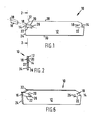
- a parting tool 10 has a blade 12 in the form of a planar support blade having plane parallel faces.
- a pocket 14 at each end of the blade 12 receives an insert 16.
- One planar surface of the blade 12 is connected by a web 18, leaving the other of the plane parallel surfaces open.
- the pocket 14 has two jaws, an upper jaw 20 and a lower jaw 22 which are tapered or V-shaped away from the leading edge 24 of the blade 12.
- the upper and lower jaws 20 and 22 may taper to a fine point forming an actual "V", it is preferred that the taper finishes in an aperture 26.
- the aperture 26 is preferably circular and passes perpendicularly through the planar surfaces of the blade 12.
- the web 18 prevents the insert 16 from being laterally ejected from the jaws 20, 22 on the planar side 34 of the tool-holder 12.
- the dovetail pocket 14 prevents the insert 16 from being ejected on the opposite side.
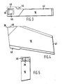
- a cutting tool arrangement comprising, a blade having at least one leading edge surface located between planar sides 34 and 36 in Figure 2 and two opposite plane parallel side faces 34 and 36 with at least one aperture, recess or pocket 14 having upper and lower jaws 20 and 22 for the retention of an insert 16, the jaws 20 and 22 being separated at one plane parallel side face 34 by a web 18, the upper and lower jaws 20 and 22 being shaped to receive and prevent lateral movement of the insert 16 when retained by the jaws 20 and 22, and an inerts 16 positioned in the aperture, recess or pocket 14, the insert 16 having on one end a seat portion as shown in Figure 3, and having walls which correspond to the geometrical configuration of the upper and lower jaws 20 and 22 and the web 18 of the blade 12, and on the other end of the insert 16 a cutting portion 40 having a cutting edge 38.
- aperture, recess or pocket 14 is tapered or V-shaped away from the leading edge 24 of blade 12 with the wider portion of the aperture, recess
- the parting-off tool has been defined, in particular with reference to a single insert, the parting-off tool may be constructed for such a single insert alone or be two-ended, such that it may be reversed and a second insert be applied to the workpiece as is shown in Figures 1 and 6.
- the tapered seat for the insert between the jaws 20 and 22, and abutting the web 18, locates the insert securely.
- the web 18 prevents the jaws 20, 22 from being forced apart under the machine forces.
- the web 18 between the jaws 20 and 22 stiffens the top part of the jaw 20 and prevents any lateral movement during mahcining.
Landscapes
- Engineering & Computer Science (AREA)
- Mechanical Engineering (AREA)
- Cutting Tools, Boring Holders, And Turrets (AREA)
- Knives (AREA)
- Auxiliary Devices For Machine Tools (AREA)
- Scissors And Nippers (AREA)
- Details Of Cutting Devices (AREA)
- Drilling Tools (AREA)
- Polishing Bodies And Polishing Tools (AREA)
Priority Applications (1)
| Application Number | Priority Date | Filing Date | Title |
|---|---|---|---|
| AT84306696T ATE56899T1 (de) | 1983-10-03 | 1984-10-01 | Schneidwerkzeug. |
Applications Claiming Priority (2)
| Application Number | Priority Date | Filing Date | Title |
|---|---|---|---|
| GB8326441 | 1983-10-03 | ||
| GB08326441A GB2147528A (en) | 1983-10-03 | 1983-10-03 | Cutting tool |
Publications (3)
| Publication Number | Publication Date |
|---|---|
| EP0138498A2 true EP0138498A2 (de) | 1985-04-24 |
| EP0138498A3 EP0138498A3 (en) | 1986-03-05 |
| EP0138498B1 EP0138498B1 (de) | 1990-09-26 |
Family
ID=10549617
Family Applications (1)
| Application Number | Title | Priority Date | Filing Date |
|---|---|---|---|
| EP84306696A Expired - Lifetime EP0138498B1 (de) | 1983-10-03 | 1984-10-01 | Schneidwerkzeug |
Country Status (10)
| Country | Link |
|---|---|
| US (1) | US4668132A (de) |
| EP (1) | EP0138498B1 (de) |
| JP (1) | JPS60146603A (de) |
| KR (1) | KR850003692A (de) |
| AT (1) | ATE56899T1 (de) |
| AU (1) | AU3348284A (de) |
| CA (1) | CA1243194A (de) |
| DE (1) | DE3483299D1 (de) |
| ES (1) | ES290197Y (de) |
| GB (1) | GB2147528A (de) |
Cited By (7)
| Publication number | Priority date | Publication date | Assignee | Title |
|---|---|---|---|---|
| EP0291933A1 (de) * | 1987-05-20 | 1988-11-23 | Sumitomo Electric Industries Limited | Abstechwerkzeug |
| EP0380541A1 (de) * | 1987-09-04 | 1990-08-08 | Kennametal Inc | Schneideinsatz mit spankontrolle. |
| EP0387636A2 (de) * | 1989-03-11 | 1990-09-19 | Zinner GmbH | Spanendes Werkzeug |
| EP0436637A1 (de) * | 1988-09-30 | 1991-07-17 | Kennametal Inc | Schneideinsatz mit spankontrolle. |
| US5037249A (en) * | 1987-09-04 | 1991-08-06 | Kennametal Inc. | Cutting insert with chip control |
| US5088862A (en) * | 1987-09-04 | 1992-02-18 | Kennametal Inc. | Cutting insert with chip control |
| WO1996033037A1 (en) * | 1995-04-20 | 1996-10-24 | Kennametal Inc. | Cutting insert with chip control |
Families Citing this family (10)
| Publication number | Priority date | Publication date | Assignee | Title |
|---|---|---|---|---|
| SE452713B (sv) * | 1986-04-07 | 1987-12-14 | Sandvik Ab | Verktyg for avstickning samt sker for anvendning i nemnda verktyg |
| JPS63154102U (de) * | 1987-03-30 | 1988-10-11 | ||
| JPS63154101U (de) * | 1987-03-30 | 1988-10-11 | ||
| AU605842B2 (en) * | 1988-03-22 | 1991-01-24 | Barend Johannes Liebenberg | Cutting tool |
| EP0878260B1 (de) * | 1997-03-27 | 2001-12-19 | Sandvik Aktiebolag | Ein- und Abstechwerkzeug |
| SE511717C2 (sv) * | 1997-05-22 | 1999-11-15 | Sandvik Ab | Hållare för svarvoperationer |
| SE516184C2 (sv) * | 1999-07-15 | 2001-11-26 | Sandvik Ab | Fastspänningsarrangemang innehållande ett hållarblad |
| USD912708S1 (en) | 2017-11-30 | 2021-03-09 | Illinois Tool Works Inc. | Cutting insert |
| USD836143S1 (en) * | 2017-11-30 | 2018-12-18 | Illinois Tool Works Inc. | Cutting insert holder |
| USD880547S1 (en) | 2017-11-30 | 2020-04-07 | Illinois Tool Works Inc. | Cutting insert |
Citations (2)
| Publication number | Priority date | Publication date | Assignee | Title |
|---|---|---|---|---|
| FR2101723A5 (de) * | 1970-08-15 | 1972-03-31 | Taper Tip Ltd | |
| FR2483820A1 (fr) * | 1980-06-06 | 1981-12-11 | Arbed | Outil de coupe constitue d'un porte-plaquette et d'une plaquette coupante qui peut etre echangee |
Family Cites Families (12)
| Publication number | Priority date | Publication date | Assignee | Title |
|---|---|---|---|---|
| FR1069769A (fr) * | 1951-12-28 | 1954-07-13 | Gereedschappenfabriek Rabenhau | Porte-outil avec outil remplaçable et jeu accessoire d'outils |
| GB790805A (en) * | 1954-12-07 | 1958-02-19 | Georg Hufnagel | Improvements relating to tools comprising hard-metal cutting bodies |
| GB1254578A (en) * | 1969-07-04 | 1971-11-24 | Wickman Wimet Ltd | Milling cutters |
| US3660877A (en) * | 1970-04-22 | 1972-05-09 | Warner Swasey Co | Cutoff tool having improved cutting tip |
| SE368785B (de) * | 1971-03-01 | 1974-07-22 | Sandvik Ab | |
| US3748710A (en) * | 1971-09-20 | 1973-07-31 | F Lynch | Tool bit holder |
| US3780408A (en) * | 1972-03-02 | 1973-12-25 | Kennametal Inc | Cutting tool |
| US4195956A (en) * | 1978-08-01 | 1980-04-01 | Wlajko Mihic | Slotting tool with exchangeable cutting insert |
| US4202651A (en) * | 1978-10-30 | 1980-05-13 | St Jean William A | Lathe tool holder |
| US4417833A (en) * | 1979-12-04 | 1983-11-29 | Iscar Ltd. | Rotary slot cutting tools |
| US4357123A (en) * | 1980-08-28 | 1982-11-02 | The Valeron Corporation | Insert retention apparatus |
| IL62278A (en) * | 1981-03-03 | 1984-10-31 | Iscar Ltd | Rotational cutting tool |
-
1983
- 1983-10-03 GB GB08326441A patent/GB2147528A/en not_active Withdrawn
-
1984
- 1984-09-25 AU AU33482/84A patent/AU3348284A/en not_active Abandoned
- 1984-09-27 CA CA000464166A patent/CA1243194A/en not_active Expired
- 1984-10-01 EP EP84306696A patent/EP0138498B1/de not_active Expired - Lifetime
- 1984-10-01 DE DE8484306696T patent/DE3483299D1/de not_active Expired - Lifetime
- 1984-10-01 AT AT84306696T patent/ATE56899T1/de active
- 1984-10-02 KR KR1019840006092A patent/KR850003692A/ko not_active Application Discontinuation
- 1984-10-03 ES ES1984290197U patent/ES290197Y/es not_active Expired
- 1984-10-03 JP JP59206447A patent/JPS60146603A/ja active Pending
-
1986
- 1986-07-11 US US06/884,886 patent/US4668132A/en not_active Expired - Fee Related
Patent Citations (2)
| Publication number | Priority date | Publication date | Assignee | Title |
|---|---|---|---|---|
| FR2101723A5 (de) * | 1970-08-15 | 1972-03-31 | Taper Tip Ltd | |
| FR2483820A1 (fr) * | 1980-06-06 | 1981-12-11 | Arbed | Outil de coupe constitue d'un porte-plaquette et d'une plaquette coupante qui peut etre echangee |
Cited By (13)
| Publication number | Priority date | Publication date | Assignee | Title |
|---|---|---|---|---|
| EP0291933A1 (de) * | 1987-05-20 | 1988-11-23 | Sumitomo Electric Industries Limited | Abstechwerkzeug |
| US5037249A (en) * | 1987-09-04 | 1991-08-06 | Kennametal Inc. | Cutting insert with chip control |
| EP0380541A4 (en) * | 1987-09-04 | 1991-01-30 | Kennametal Inc. | Cutting insert with chip control |
| EP0380541A1 (de) * | 1987-09-04 | 1990-08-08 | Kennametal Inc | Schneideinsatz mit spankontrolle. |
| US5088862A (en) * | 1987-09-04 | 1992-02-18 | Kennametal Inc. | Cutting insert with chip control |
| EP0616867A2 (de) * | 1987-09-04 | 1994-09-28 | Kennametal Inc. | Schneideinsatz mit Spankontrolle |
| EP0616867A3 (de) * | 1987-09-04 | 1995-02-08 | Kennametal Inc | Schneideinsatz mit Spankontrolle. |
| EP0436637A1 (de) * | 1988-09-30 | 1991-07-17 | Kennametal Inc | Schneideinsatz mit spankontrolle. |
| EP0436637A4 (en) * | 1988-09-30 | 1991-10-09 | Kennametal Inc. | Cutting insert with chip control |
| EP0387636A2 (de) * | 1989-03-11 | 1990-09-19 | Zinner GmbH | Spanendes Werkzeug |
| EP0387636A3 (de) * | 1989-03-11 | 1991-02-06 | Zinner GmbH | Spanendes Werkzeug |
| WO1996033037A1 (en) * | 1995-04-20 | 1996-10-24 | Kennametal Inc. | Cutting insert with chip control |
| US5704737A (en) * | 1995-04-20 | 1998-01-06 | Kennametal Inc. | Cutting insert with chip control |
Also Published As
| Publication number | Publication date |
|---|---|
| US4668132A (en) | 1987-05-26 |
| ES290197U (es) | 1986-03-01 |
| DE3483299D1 (de) | 1990-10-31 |
| GB2147528A (en) | 1985-05-15 |
| EP0138498B1 (de) | 1990-09-26 |
| EP0138498A3 (en) | 1986-03-05 |
| ATE56899T1 (de) | 1990-10-15 |
| ES290197Y (es) | 1986-10-16 |
| AU3348284A (en) | 1985-04-18 |
| GB8326441D0 (en) | 1983-11-02 |
| KR850003692A (ko) | 1985-06-26 |
| JPS60146603A (ja) | 1985-08-02 |
| CA1243194A (en) | 1988-10-18 |
Similar Documents
| Publication | Publication Date | Title |
|---|---|---|
| US4357123A (en) | Insert retention apparatus | |
| EP0138498A2 (de) | Schneidwerkzeug | |
| KR100272500B1 (ko) | 인써트 클램핑 수단을 구비한 절삭공구 | |
| EP0152729B1 (de) | Verspannendes Schneidwerkzeug | |
| US6234727B1 (en) | Resilient clamping mechanism for inserts | |
| EP0851796B1 (de) | Schneidewerkzeug mit wendeplattenspannvorrichtung | |
| KR100645945B1 (ko) | 절삭 공구 조립체 | |
| EP1345723B1 (de) | Schneidwerkzeug | |
| US5921724A (en) | Insert and toolholder for machining operations | |
| US4443136A (en) | Machine cutting tool | |
| BG109694A (bg) | Режещ инструмент и режеща вложка за него | |
| EP0202209B1 (de) | Werkzeug und Einsatz, z.B. zum Drehen | |
| KR101713350B1 (ko) | 절삭 공구 및 절삭 공구용 절삭 인서트 | |
| WO2013114353A1 (en) | Tool holder and method for clamping a cutting insert therein | |
| KR100767164B1 (ko) | 절삭 공구 조립체 | |
| EP0420512A1 (de) | Schneideinsatz und Schneidwerkzeug für dieser Einsatz | |
| US5449255A (en) | Cutting insert having multiple chip breaker surfaces | |
| JP3045918U (ja) | ツールホルダ組立体 | |
| US7331736B2 (en) | Metal cutting tool | |
| SU1720804A1 (ru) | Режущий инструмент | |
| EP0205886A2 (de) | Fingerfräser | |
| JPH0871810A (ja) | 溝入れ用バイト | |
| CS246611B1 (en) | Cutting tool |
Legal Events
| Date | Code | Title | Description |
|---|---|---|---|
| PUAI | Public reference made under article 153(3) epc to a published international application that has entered the european phase |
Free format text: ORIGINAL CODE: 0009012 |
|
| AK | Designated contracting states |
Designated state(s): AT BE CH DE FR GB IT LI NL SE |
|
| PUAL | Search report despatched |
Free format text: ORIGINAL CODE: 0009013 |
|
| AK | Designated contracting states |
Kind code of ref document: A3 Designated state(s): AT BE CH DE FR GB IT LI NL SE |
|
| 17P | Request for examination filed |
Effective date: 19860826 |
|
| 17Q | First examination report despatched |
Effective date: 19870908 |
|
| RAP1 | Party data changed (applicant data changed or rights of an application transferred) |
Owner name: CARBOLOY INC. |
|
| GRAA | (expected) grant |
Free format text: ORIGINAL CODE: 0009210 |
|
| AK | Designated contracting states |
Kind code of ref document: B1 Designated state(s): AT BE CH DE FR GB IT LI NL SE |
|
| PG25 | Lapsed in a contracting state [announced via postgrant information from national office to epo] |
Ref country code: SE Effective date: 19900926 Ref country code: NL Effective date: 19900926 Ref country code: LI Effective date: 19900926 Ref country code: IT Free format text: LAPSE BECAUSE OF FAILURE TO SUBMIT A TRANSLATION OF THE DESCRIPTION OR TO PAY THE FEE WITHIN THE PRESCRIBED TIME-LIMIT;WARNING: LAPSES OF ITALIAN PATENTS WITH EFFECTIVE DATE BEFORE 2007 MAY HAVE OCCURRED AT ANY TIME BEFORE 2007. THE CORRECT EFFECTIVE DATE MAY BE DIFFERENT FROM THE ONE RECORDED. Effective date: 19900926 Ref country code: FR Effective date: 19900926 Ref country code: CH Effective date: 19900926 Ref country code: BE Effective date: 19900926 Ref country code: AT Effective date: 19900926 |
|
| REF | Corresponds to: |
Ref document number: 56899 Country of ref document: AT Date of ref document: 19901015 Kind code of ref document: T |
|
| REF | Corresponds to: |
Ref document number: 3483299 Country of ref document: DE Date of ref document: 19901031 |
|
| PG25 | Lapsed in a contracting state [announced via postgrant information from national office to epo] |
Ref country code: GB Effective date: 19901126 |
|
| REG | Reference to a national code |
Ref country code: CH Ref legal event code: PL |
|
| EN | Fr: translation not filed | ||
| NLV1 | Nl: lapsed or annulled due to failure to fulfill the requirements of art. 29p and 29m of the patents act | ||
| GBPC | Gb: european patent ceased through non-payment of renewal fee | ||
| PLBE | No opposition filed within time limit |
Free format text: ORIGINAL CODE: 0009261 |
|
| STAA | Information on the status of an ep patent application or granted ep patent |
Free format text: STATUS: NO OPPOSITION FILED WITHIN TIME LIMIT |
|
| 26N | No opposition filed | ||
| PGFP | Annual fee paid to national office [announced via postgrant information from national office to epo] |
Ref country code: DE Payment date: 20031009 Year of fee payment: 20 |