EP0205886A2 - Fingerfräser - Google Patents
Fingerfräser Download PDFInfo
- Publication number
- EP0205886A2 EP0205886A2 EP86106524A EP86106524A EP0205886A2 EP 0205886 A2 EP0205886 A2 EP 0205886A2 EP 86106524 A EP86106524 A EP 86106524A EP 86106524 A EP86106524 A EP 86106524A EP 0205886 A2 EP0205886 A2 EP 0205886A2
- Authority
- EP
- European Patent Office
- Prior art keywords
- cutter head
- slots
- inserts
- diameter
- cutting
- Prior art date
- Legal status (The legal status is an assumption and is not a legal conclusion. Google has not performed a legal analysis and makes no representation as to the accuracy of the status listed.)
- Withdrawn
Links
Images
Classifications
-
- B—PERFORMING OPERATIONS; TRANSPORTING
- B23—MACHINE TOOLS; METAL-WORKING NOT OTHERWISE PROVIDED FOR
- B23C—MILLING
- B23C5/00—Milling-cutters
- B23C5/16—Milling-cutters characterised by physical features other than shape
- B23C5/20—Milling-cutters characterised by physical features other than shape with removable cutter bits or teeth or cutting inserts
- B23C5/22—Securing arrangements for bits or teeth or cutting inserts
- B23C5/2239—Securing arrangements for bits or teeth or cutting inserts with cutting inserts clamped by a clamping member acting almost perpendicular on the cutting face
- B23C5/2243—Securing arrangements for bits or teeth or cutting inserts with cutting inserts clamped by a clamping member acting almost perpendicular on the cutting face for plate-like cutting inserts
-
- Y—GENERAL TAGGING OF NEW TECHNOLOGICAL DEVELOPMENTS; GENERAL TAGGING OF CROSS-SECTIONAL TECHNOLOGIES SPANNING OVER SEVERAL SECTIONS OF THE IPC; TECHNICAL SUBJECTS COVERED BY FORMER USPC CROSS-REFERENCE ART COLLECTIONS [XRACs] AND DIGESTS
- Y10—TECHNICAL SUBJECTS COVERED BY FORMER USPC
- Y10T—TECHNICAL SUBJECTS COVERED BY FORMER US CLASSIFICATION
- Y10T29/00—Metal working
- Y10T29/49—Method of mechanical manufacture
- Y10T29/49826—Assembling or joining
- Y10T29/49895—Associating parts by use of aligning means [e.g., use of a drift pin or a "fixture"]
Definitions
- This invention relates to end milling cutters for machine tools and, more particularly, to end milling cutters utilizing replaceable cutting inserts.
- End milling cutters have previously utilized replaceable cutting inserts which are retained between cooperating jaw elements formed in the cutter head.
- An end milling cutter of this general type is shown in Canadian Patent No. 944139. The accurate positioning of the cutting edges of the inserts, however, has posed a problem with cutters of this type.
- an end milling cutter comprising a shank having a cutter head, the cutter head having a central longitudinal axis and an end face; a pair of opposed slots formed in the cutter head, each of the slots extending longitudinally inwardly away from the end face and generally radially from the central longitudinal axis to an external or lateral surface of the cutter head, the pair of slots separating a pair of cooperating jaw elements defined by the cutter head, each jaw element including a transversely extending shoulder located within a respective one of the slots and extending from the central longitudinal axis to the lateral surface of the cutter head; a cutting insert received in each of the slots, the insert having at least three sides, the shoulder in each slot engaging and supporting one side of the insert received in the slot, a pair of dimples, one on each of the jaw elements, each dimple engaging a second side of the insert received in the slot, and clamping means to retain the inserts within their respective slots.
- the shoulders are inclined relative to the lateral surface of the cutter head and are each inclined in an opposite direction to the other.
- the dimples are disposed on opposite sides of a diameter of the cutter head and extend inwardly of the cutter head from the end face thereof.
- the inserts are triangular inserts.
- the present invention further provides a method of making an end milling cutter, said method comprising the steps of cutting a pair of substantially radially extending first slots on opposite sides of a diameter of a cutter head, which is mounted on a shank, the first slots being of a width substantially equal to the thickness of a cutting insert; cutting a pair of second slots in the cutter head, the second slots extending the first slots longitudinally of the cutter head, the second slots extending radially inwardly from the lateral surface of the cutter head to the central longitudinal axis thereof, and being of a width less than the width of the first slots, such that each of the first slots form a shoulder; providing means to clamp cutting inserts in the slots, placing a cutting insert in each of the first slots, one side of each of the inserts engaging with and being supported by the respective shoulder of each slot; placing the cutter head and the inserts in a fixture, the fixture having a first cylindrical inner surface, the diameter of the first cylindrical inner surface being greater than the diameter of the cutter head and equal to a desired cutting diameter at which
- the step of providing clamping means comprises drilling a radially extending hole through the jaw elements of the cutter head, the hole being substantially normal to the first and second slots; tapping part of the hole in one jaw element, introducing a clamping screw into the hole through the cutter jaw element; and said clamping step comprises tightening the clamping screw to draw the jaw elements together to retain the inserts in the first slots when the cutter head and the inserts are in the fixture.
- said shank is a substantially cylindrical shank on the cutter head, the diameter of the shank being less than the diameter of the cutter head, the fixture having a cylindrical support hole coaxial with the first cylindrical surface, with the support hole having a diameter substantially equal to or slightly greater than the diameter of the shank, but less than the diameter of the first cylindrical inner surface, thus forming a shoulder in the fixture; the method comprising the step of placing the shank in the support hole to support the shank, the cutter head being supported by the shoulder of the fixture.
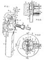
- an end milling cutter 10 comprises a shank 12 of high-speed steel having at one end 13 a substantially cylindrical cutter head 14 with a conically dished end face 16 substantailly normal to the longitudinal axis 18 thereof.
- the diameter of the shank 12 is less than the diameter of the cutter head 14.
- a cylindrical bore 20 is drilled coaxially with the longitudinal axis 18 of the cutter head 14 and extends longitudinally inwardly from the end face 16 over the length of the head 14.
- a pair of substantially radially extending negative rake, opposed slots 22 are cut in the end of the cutter head I4 adjacent the end face 16 on either side of a diameter 48 of the head 14 and at an angle of about sixty degrees with respect to the lateral surface 24 of the head 14.
- Each of the slots 22 is sloped oppositely to the other (see Figures 4 and 6).
- the slots 22 each have a region of a width substantially equal to the thickness of a cutting insert 26.
- the slots 22 extend longitudinally inwardly from the end face 16 and substantially radially from the lateral surface 24, extending to the bore 20 as shown (see Figure I).
- the slots 22 are shown with negative rake, they can also be at neutral or positive rake angles.
- a second pair of slots 28 are cut in the head 14 at a lesser width than the slots 22.
- the slots 28 extend the slots 22 longitudinally of the cutter head 14 and also extend radially inwardly from the lateral surface 24 to the bore 20.
- the slots 22 form supporting shoulders 30 located on both sides of and above slots 28.
- the bore 20 and the slots 22 and 28 define a pair of cooperating jaw elements 31 in the cutter head 14.
- the lateral surface 24 of the head 14 is milled, on opposite sides, adjacent the slots 22 to form swarf clearance cut-outs 32 to allow for adequate swarf removal.
- a socket head cap screw 33 is received in a drilled, tapped, counterbored and substantially radially extending hole 34 passing through the jaw elements 31 transversely of the longitudinal axis 18 of the cutter head 14.
- the hole 34 is substantially normal to the slots 22 and 28 and intersects the bore 20, as shown in Figure 2.
- the screw 33 when tightened, clamps the inserts 26 in the slots 22 between the jaw elements 31, by drawing the jaw elements 31 together.
- a pair of pressed dimples 44 one on each of the jaw elements 31, extend inwardly of the head 14 from the end face 16 to engage and support a second side 46 of each of the inserts 26.
- the dimples 44 are positioned substantially adjacent the bore 20 on opposite sides of a diameter 48 of the head 14, such that part of each dimple 44 is located above one of the slots 22.
- a feature of the invention resides in the method of making the cutter 10 such that the cutting edges 40 of the inserts 26 are positioned on a prescribed diameter.
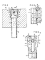
- a fixture 50 (see Figures 2, 3 and 4) is utilized for this purpose.
- the fixture 50 includes a central bore 52 with a first cylindrical inner surface 54, the diameter of which is greater than that of the head 14 but which is precisely equal to the desired cutting diameter at which the edges 40 of the inserts 26 should be positioned.
- the bore 52 further comprises a cylindrical support hole 56 which is coaxial with the surface 54 and has a diameter substantially equal to or slightly greater than, that of the shank 12. Because the diameter of the hole 56 is less than that of the bore with the surface 54, a shoulder 58 is formed in the fixture 50.
- a method of making a cutter such as is described above comprises the steps of first drilling the cylindrical bore 20 coaxially of the cutter head 14 and substantially coextensive in length therewith and then cutting the slots 22 in opposite halves of the head 14 to a width substantially equal to the thickness of the cutting inserts 26.
- the slots 22 are cut at an angle of approximately sixty degrees with respect to the lateral surface 24 of the head 14, each of the slots 22 being sloped oppositely to the other, and extending longitudinally inwardly from the end face 16 and substantially radially from surface 24 to bore 20.
- the slots 28 are then cut in the head 14, extending the first slots 22 longitudinally of the head 14 and extending radially inwardly from the surface 24 to the bore 20.
- the slots 28 are of lesser width than the slots 22, whereby supporting shoulders 30 are formed on the sides of the slots 28.
- the bore 20 and the slots 22 and 28 define jaw elements 31 of the cutter 10.
- the cutter 10 is then placed in the fixture 50, the shank 12 being received in the support hole 56 and the head 14 being received within the surface 54 and supported by the shoulder 58. The cutter is thus supported by the fixture.
- a set screw 60 in the fixture 50 is then tightened to hold the shank 12 securely in position, the screw 60 engaging a flat 62 on the shank 12.
- the inserts 26 are then placed in the slots 22 such that the sides 42 thereof slide radially outwardly along the shoulders 30 until the edges 40 of the inserts contact the surface 54. See Figures 2 and 4.
- the screw 33 is then lightly tightened by means of an alien wrench 63 inserted through a slot 64 in the fixture 50.
- the cutter 10 is then ready for dimpling.
- dimples 44 are then pressed longitudinally inwardly of each jaw element 31 from the end face 16 perpendicular to the sides 46 of each insert on opposite sides of the cutter head diameter 48.
- the dimpling thus produces a force on each insert which has the effect of driving the insert down the shoulder that supports it, so that the insert moves radially outwardly.
- the pressing of the dimples 44 forces the cutting edges 40 of the triangular inserts 26 into position abutting the inner surface 54 of the fixture 50, the dimples 44 contacting the second sides 46 of the inserts 26, the diametrical extent of the cutting edges 40 thereby being made precisely equal to the diameter of the cylindrical surface 54 of the fixture 50.
- the clamping screw 33 may be slightly loosened before pressing the dimples 44.
- the cutter is then removed from the fixture 50 and the screw 33 is fully tightened, thus holding the inserts 26 tightly in place.
- the insert may be removed from the slots, rotated and replaced with a new cutting edge in the desired position by the procedure described above.
- an end milling cutter comprising: a shank having a generally cylindrical cutter head, the cutter head having an end face substantially normal to the axis thereof; a cylindrical bore extending longitudinally inwardly of the cutter head from the end face, the bore being coaxial with the cutter head and being substantially equal in length to the length of the cutter head; a pair of opposed slots formed in the cutter head, each of the slots extending longitudinally inwardly from the end face and generally radially from the cylindrical bore to the lateral surface of the cutter head, the pair of slots and the bore defining a pair of cooperating jaw elements in the cutter head, each of the jaw elements including a transversely-extending, insert-supporting shoulder on at least one side of the slot, the shoulder extending from the bore to the lateral surface of the cutter head; a cutting insert received in each of the slots, the insert having at least three sides, the shoulder in each slot engaging and supporting one side of the insert received in the slot; a pair of pressed dimples, one on each of the jaw elements
- the shoulders extend at an angle of about 60° with respect to the lateral surface of the cutter head, each shoulder being sloped oppositely to the other, and the insert is a triangular insert.
- the present invention also provides a method of making an end milling cutter having a pair of cooperating jaw elements defining opposed slots in a cutter head, the head having a pair of cutting inserts having cutting edges on a prescribed diameter, comprising: drilling a cylindrical bore in a cylindrical end milling cutter head, the bore being coaxial with the cutter head and generally co-extensive in length therewith; cutting a pair of generally radially extending first slots in opposite sides of the cutter head, the first slots being of a width substantially equal to the thickness of a cutting insert, the first slots extending longitudinally inwardly from the end face of the cutter and generally radially from the lateral surface of the cutter head to the cylindrical bore; cutting a pair of second slots in the cutter head, the second slots extending the first slots longitudinally of the cutter head, the second slots extending radially inwardly from the lateral surface of the cutter head to the cylindrical bore, the second slots being of a width less than the width of the first slots, whereby each of the first slots form a supporting shoulder on at least one
Landscapes
- Engineering & Computer Science (AREA)
- Mechanical Engineering (AREA)
- Milling Processes (AREA)
- Drilling Tools (AREA)
Applications Claiming Priority (2)
| Application Number | Priority Date | Filing Date | Title |
|---|---|---|---|
| US06/736,947 US4596166A (en) | 1985-05-22 | 1985-05-22 | End milling cutter and method of making same |
| US736947 | 1985-05-22 |
Publications (2)
| Publication Number | Publication Date |
|---|---|
| EP0205886A2 true EP0205886A2 (de) | 1986-12-30 |
| EP0205886A3 EP0205886A3 (de) | 1988-02-03 |
Family
ID=24961989
Family Applications (1)
| Application Number | Title | Priority Date | Filing Date |
|---|---|---|---|
| EP86106524A Withdrawn EP0205886A3 (de) | 1985-05-22 | 1986-05-14 | Fingerfräser |
Country Status (4)
| Country | Link |
|---|---|
| US (1) | US4596166A (de) |
| EP (1) | EP0205886A3 (de) |
| JP (1) | JPS61270013A (de) |
| CN (1) | CN86103463A (de) |
Families Citing this family (3)
| Publication number | Priority date | Publication date | Assignee | Title |
|---|---|---|---|---|
| CN102632287A (zh) * | 2012-04-15 | 2012-08-15 | 苏州怡信光电科技有限公司 | 一种转盘铣刀 |
| CN206869205U (zh) * | 2017-10-12 | 2018-01-12 | 晋城富泰华精密电子有限公司 | 铣刀 |
| US11241747B2 (en) * | 2017-10-16 | 2022-02-08 | Iscar, Ltd. | Cutting tool and undersized bore-less indexable insert therefor |
Citations (4)
| Publication number | Priority date | Publication date | Assignee | Title |
|---|---|---|---|---|
| US3380137A (en) * | 1966-05-12 | 1968-04-30 | Valeron Corp | Cylindrical insert cutting tool |
| FR2163915A5 (de) * | 1971-12-06 | 1973-07-27 | Ind Precision Mecanique | |
| US4116579A (en) * | 1976-08-25 | 1978-09-26 | Martin Norman Hamilton | End mill tool holder body and tool |
| DE2653302A1 (de) * | 1976-11-24 | 1978-10-12 | Koerber Geb Hof Anna | Kugelbahn- bzw. fingerfraeser |
Family Cites Families (10)
| Publication number | Priority date | Publication date | Assignee | Title |
|---|---|---|---|---|
| US1614288A (en) * | 1921-11-02 | 1927-01-11 | Barber Colman Co | Milling cutter |
| US1798314A (en) * | 1926-03-03 | 1931-03-31 | Cleveland Twist Drill Co | Process of making spiral reamers |
| US2345462A (en) * | 1940-11-29 | 1944-03-28 | Coughlin Daniel Josef | Cutting tool holder |
| US2400856A (en) * | 1943-07-16 | 1946-05-21 | Pipe Machinery Company | Cutting tool |
| US3217384A (en) * | 1962-02-26 | 1965-11-16 | Sandvikens Jernverks Ab | Milling cutter |
| US3551978A (en) * | 1968-10-31 | 1971-01-05 | Fan Steel Inc | Rotary end mill cutter |
| US3633258A (en) * | 1970-05-22 | 1972-01-11 | Ernest B Szabo | Insert tool holder and cutting tool therefor |
| CA944139A (en) * | 1970-10-01 | 1974-03-26 | Harold W. Lindsay | End milling cutter |
| US3814536A (en) * | 1972-09-27 | 1974-06-04 | P Garrett | Boring bar |
| US4096613A (en) * | 1977-03-25 | 1978-06-27 | Triangle Grinding, Inc. | Cutting tool |
-
1985
- 1985-05-22 US US06/736,947 patent/US4596166A/en not_active Expired - Fee Related
-
1986
- 1986-05-07 JP JP61103236A patent/JPS61270013A/ja active Pending
- 1986-05-14 EP EP86106524A patent/EP0205886A3/de not_active Withdrawn
- 1986-05-21 CN CN86103463A patent/CN86103463A/zh active Pending
Patent Citations (4)
| Publication number | Priority date | Publication date | Assignee | Title |
|---|---|---|---|---|
| US3380137A (en) * | 1966-05-12 | 1968-04-30 | Valeron Corp | Cylindrical insert cutting tool |
| FR2163915A5 (de) * | 1971-12-06 | 1973-07-27 | Ind Precision Mecanique | |
| US4116579A (en) * | 1976-08-25 | 1978-09-26 | Martin Norman Hamilton | End mill tool holder body and tool |
| DE2653302A1 (de) * | 1976-11-24 | 1978-10-12 | Koerber Geb Hof Anna | Kugelbahn- bzw. fingerfraeser |
Also Published As
| Publication number | Publication date |
|---|---|
| JPS61270013A (ja) | 1986-11-29 |
| EP0205886A3 (de) | 1988-02-03 |
| CN86103463A (zh) | 1986-12-03 |
| US4596166A (en) | 1986-06-24 |
Similar Documents
| Publication | Publication Date | Title |
|---|---|---|
| EP0042237B1 (de) | Zerspanungswerkzeug und Schneidkörper dafür | |
| KR101089525B1 (ko) | 절삭 인서트와 홀더 사이에서 돌출부와 홈이 상호 작용하는밀링 공구 | |
| EP1159101B1 (de) | Werkzeughalter mit ersetzbarem einsatzträger | |
| EP1113895B1 (de) | Bohrwerkzeugzusammenbau | |
| EP0312223A1 (de) | Schneideinsatz und Werkzeughalter dafür | |
| US4509886A (en) | Cutting tool with cutting inserts having positioning keyways | |
| EP1635976B1 (de) | Schneideinsatz mit ecken mit unterschiedlichen radien | |
| US4668132A (en) | Cutting tool | |
| US4645383A (en) | End milling cutter and method of making same | |
| US4118138A (en) | Cutting tool | |
| EP0179033A2 (de) | Schneidwerkzeug | |
| EP0526438A2 (de) | Schneidwerkzeug | |
| US4525109A (en) | Cutting tool having a cutting blade in a shank slot | |
| EP1286800B1 (de) | Schneidwerkzeuganordnung | |
| EP1283082B1 (de) | Drehendes Schneidwerkzeug | |
| EP0205886A2 (de) | Fingerfräser | |
| US4087194A (en) | Cutting tool | |
| IE42806B1 (en) | Improvements in cutting tools having disposable inserts | |
| US6648560B2 (en) | Cutting insert | |
| US3566496A (en) | Form tool | |
| US4137000A (en) | Cutting tool | |
| EP0638385A1 (de) | Schneidwerkzeug | |
| JP4867376B2 (ja) | 切削工具 | |
| EP0096669A1 (de) | Fräser mit auswechselbaren Schneideinsätzen | |
| US4043699A (en) | Counterbore tool |
Legal Events
| Date | Code | Title | Description |
|---|---|---|---|
| PUAI | Public reference made under article 153(3) epc to a published international application that has entered the european phase |
Free format text: ORIGINAL CODE: 0009012 |
|
| AK | Designated contracting states |
Kind code of ref document: A2 Designated state(s): AT BE CH DE FR GB IT LI LU NL SE |
|
| PUAL | Search report despatched |
Free format text: ORIGINAL CODE: 0009013 |
|
| AK | Designated contracting states |
Kind code of ref document: A3 Designated state(s): AT BE CH DE FR GB IT LI LU NL SE |
|
| STAA | Information on the status of an ep patent application or granted ep patent |
Free format text: STATUS: THE APPLICATION IS DEEMED TO BE WITHDRAWN |
|
| 18D | Application deemed to be withdrawn |
Effective date: 19880804 |