EP0138370A2 - Apparat zur Anwendung in Leckdetektion - Google Patents
Apparat zur Anwendung in Leckdetektion Download PDFInfo
- Publication number
- EP0138370A2 EP0138370A2 EP84306133A EP84306133A EP0138370A2 EP 0138370 A2 EP0138370 A2 EP 0138370A2 EP 84306133 A EP84306133 A EP 84306133A EP 84306133 A EP84306133 A EP 84306133A EP 0138370 A2 EP0138370 A2 EP 0138370A2
- Authority
- EP
- European Patent Office
- Prior art keywords
- skirt
- sample volume
- carrier member
- gas
- brush
- Prior art date
- Legal status (The legal status is an assumption and is not a legal conclusion. Google has not performed a legal analysis and makes no representation as to the accuracy of the status listed.)
- Withdrawn
Links
Images


Classifications
-
- G—PHYSICS
- G01—MEASURING; TESTING
- G01M—TESTING STATIC OR DYNAMIC BALANCE OF MACHINES OR STRUCTURES; TESTING OF STRUCTURES OR APPARATUS, NOT OTHERWISE PROVIDED FOR
- G01M3/00—Investigating fluid-tightness of structures
- G01M3/02—Investigating fluid-tightness of structures by using fluid or vacuum
- G01M3/04—Investigating fluid-tightness of structures by using fluid or vacuum by detecting the presence of fluid at the leakage point
-
- G—PHYSICS
- G01—MEASURING; TESTING
- G01M—TESTING STATIC OR DYNAMIC BALANCE OF MACHINES OR STRUCTURES; TESTING OF STRUCTURES OR APPARATUS, NOT OTHERWISE PROVIDED FOR
- G01M3/00—Investigating fluid-tightness of structures
- G01M3/02—Investigating fluid-tightness of structures by using fluid or vacuum
- G01M3/04—Investigating fluid-tightness of structures by using fluid or vacuum by detecting the presence of fluid at the leakage point
- G01M3/20—Investigating fluid-tightness of structures by using fluid or vacuum by detecting the presence of fluid at the leakage point using special tracer materials, e.g. dye, fluorescent material, radioactive material
- G01M3/202—Investigating fluid-tightness of structures by using fluid or vacuum by detecting the presence of fluid at the leakage point using special tracer materials, e.g. dye, fluorescent material, radioactive material using mass spectrometer detection systems
- G01M3/205—Accessories or associated equipment; Pump constructions
Definitions
- This invention relates to apparatus for use in the detection of leaks particularly but not exclusively in vehicle bodies.
- European Patent Application 0064880 discloses the use of such a method to detect leaks particularly in the door and window seals of a car body, the signal gas, helium, being supplied at slightly above atmospheric pressure to the interior of the body and one or more sensors searching particularly the seal areas of the exterior of the body.
- the sensoring arrangement of European Patent Application 0064880 includes a sensing probe which communicates with a predetermined sample volume defined between the sensing head and the body of the car and bounded by an annular air curtain, a leak being detected when the exit end of the leakage path lies within the area of the body bounded by the air curtain.
- the sensor arrangement disclosed in European Patent Application 0064880 does not perform satisfactorily when it is used to search a surface which has an edge or a curve of significant radius since as the sensor arrangement overlaps the edge or curve, the air curtain can cease to be effective in defining the closed boundary of the sample volume and thus a leak at or adjacent an edge or curve of the surface may not be detected. Moreover external turbulent airflows may breakdown the air curtain with the attendant risk of false readings being generated. It is an object of the present invention to provide apparatus for use in leak detection wherein this problem are minimised.
- apparatus for use in the detection of leaks includes, an annular flexible, gas permeable skirt carried by and projecting from a carrier member which closes one axial end of the skirt, the opposite axial end of the skirt being closed in use by engagement with the surface being searched, such that said surface and said carrier member contain between them a sample volume bounded by said skirt, and, a sensing probe communicating with said sample volume for detecting the presence of a signal gas in said sample volume.
- said skirt is defined by an annular brush having its flexible filaments extending generally parallel to the axis of the annulus defined by the brush.
- the region of the carrier member within the confines of the skirt, which defines a closure for said one axial end of the skirt, is formed with one or more apertures through which gas can be supplied to or drawn from said sample volumes.
- said carrier member is a hollow body having an end plate forming at least part of the closure at said one axial end of the skirt, said probe extending through said end plate to communicate with said sample volume and being disposed at or adjacent the axis of said skirt, the body defining a chamber which communicates with said sample volume by way of a plurality of apertures in the end cap, said apertures being distributed around said probe and said body including a gas port whereby gas may be supplied to or drawn from said chamber and by way of said apertures to or from said sample volume.
- said carrier member is provided with gas flow passage means whereby in use an annular air curtain can be generated around the exterior of said skirt.
- the apparatus includes a second annular flexible skirt carried by and projecting from said carrier member and closed at one axial end by said carrier member, said first and second skirts being disposed co-axially of one another, and said air curtain being generated in use in an annular gap defined between said co-axial first and second skirts.
- first and second skirts are defined by respective annular brushes, each brush having its flexible filaments extending generally parallel to the axis of the annulus defined by the brush.
- Figure 1 is a cross-sectional representation of apparatus for use in the detection of leaks in accordance with one example of the present invention
- the apparatus includes a hollow body 10 containing a chamber 11.
- the body 10 is of cylindrical form, being of circular cross-section and having an integral top plate 12.
- the axial end of the body 10 remote from the top plate 12 is closed by an end cap 13.
- the wall of the body 10 is formed with a port 14 to which in use is connected an air line.
- air may be supplied to or withdrawn from the chamber 11.
- Passing through the top plate 12 and the end cap 13 and aligned with the axis of the body 10 is a sensor probe 15 the operative end 16 of the probe being exposed at the face of the end cap 13 remote from the top plate 12. Where the probe 15 passes through the top plate 12 and the end cap 13 seals are provided to seal the interface of the probe 15 and the body 10.
- the known sensor probe 15 is coupled in known manner to a known gas detector 17.
- An annular, flexible, gas permeable skirt 18 is positioned with one of its axial ends encircling, and detachably secured to, the end of the body 10 remote from the top plate 12.
- the axial length of the annular skirt 18 is such that the skirt protrudes by a predetermined distance beyond the outer face of the end cap 13 and in use the free end of the skirt 18 slidably engages the surface of the member 19 which is to be searched for leaks.
- a sample volume 21 is contained between the outer face of the end cap 13 and the surface of the member 19 presented to the end cap 13, and is bounded by the skirt 18.
- the operative end 16 of the probe 15 communicates with the sample volume 21.
- the end cap 13 is formed with a plurality of fine passages 22 which are distributed around the probe 15 and by way of which the chamber 11 communicates with the sample volume 21.
- the skirt 18 is defined by an annular brush composed of a plurality of fine, flexible, elongate filaments 23 disposed generally parallel to the axis of the body 10, and secured at one end in an annular stock 24 detachably secured to the outer surface of the body 10.
- the body 10 is carried by a mechanism whereby the body 10 can be traversed over the whole of, or a predetermined area of, the top surface of the member 19.
- the opposite surface of the member 19 is subjected to helium gas, or a mixture of helium and air at a pressure which slightly exceeds ambient atmospheric pressure whereby in the event of a leak 25 in the member 19 helium gas will pass through the leakage path and be present in the region of the leak at the upper side of the member 19.
- Air under pressure is admitted by way of the port 14 to the chamber 11 and thus there is a flow of air through the drillings 22 and into the sample volume 21.
- the pressure within the sample volume 21 does not however exceed the pressure at the underside of the member 19, and thus the flow of signal gas (helium) through any leak is not prevented.
- the body 10 carrying with it the skirt 18, is moved over the upper surface of the member 19 helium from the underside of the member 19 will enter the sample volume 21 when the leak lies within the area of the member 19 bounded at any given time by the skirt 18.
- the atmosphere within the sample volume 21 is continually being sampled by the probe 15, and the sample taken by the probe 15 is continually being scrutinized by the detector 17.
- the inertia, or hysteresis, of the probe 15 and detector 17 is very small, and thus substantially immediately the skirt 18 encircles an area of the member 19 containing a leak, helium entering the sample volume 21 will be detected by the detector 17.
- the flow of air into the sample volume 21 through the drillings 22 ensures continual gentle mixing of the atmosphere in the sample volume 21 and thus even if the leak is closely adjacent the skirt 18 the mixing effect within the volume 21 will ensure that the helium is detected by the probe 15 and detector 17.
- the use made of detection of helium by the detector 17 is conventional, and forms no part of the present invention.
- the apparatus itself may include a marking device for marking the member 19 in the region of the leak.
- the position of the body 10 at any given instant can automatically be plotted in relation to a chart representing the body of the vehicle, and the chart can be marked whenever a leak is detected. In this way the car body itself would not need to be marked and the chart can be examined at the end of the search procedure and the position of any leaks can then be identified from the chart for subsequent repair.
- Air entering the sample volume 21 by way of the drillings 22 leaves the sample volume by percolating through the skirt 18.
- any residual helium within the sample volume 21 is rapidly purged by the continued flow of air through the drillings 22.
- spurious leak detection is avoided.
- the port 14 is connected to a vacuum source so that air is drawn from the sample volume 21 by way of the drillings 22 and the chamber 11. Air will then enter the sample volume 21 by percolating through the gas permeable skirt 18, and again there will be effective mixing, and purging of the atmosphere within the sample volume 21.
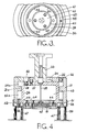
- the apparatus includes a composite hollow body 30 consisting of an outer cylindrical member 31 partially closed at its upper end by an integral flange 32. Positioned within, and closing the circular aperture of the flange 32 is the flanged lower end 34 of a hollow cylindrical supporting stem 33 whereby the apparatus is carried in use from, for example, a robot or other computer controlled arm.
- a gas sensor probe 35 extends through the central passage of the stem 33.
- an inner cylindrical member 36 Disposed within the outer cylindrical member 31 is an inner cylindrical member 36 partially closed at its end adjacent the stem 33 by an integral circumferential flange 37.
- the central aperture of the flange 37 is closed by one end of a core member 38 which is in screw threaded engagement with the wall of the aperture of the flange 37, and which extends axially within the inner cylindrical member 36.
- the core member 38 is formed with an axially extending passage 35a with which the probe 35 communicates.
- the end of the core member 38 remote from the flange 37 is formed with a radially outwardly extending flange 39, the outermost face of which is provided with a recess 41 into which the passage 35a opens.
- a baffle plate 42 is secured to the member 38 within the recess 41 and overlies the open end of the passage 35a without closing the open end of the passage.
- the outer diameter of the flange 39 of the member 38 is equal to the inner diameter of the adjacent region of the member 36 so that the members 36 and 38 together with their flanges 37 and 39 define an annular chamber 43 within the body 30.
- the periphery of the flange 39 is cut away over four equi-angularly spaced regions 44 so as to provide access to the chamber 43 around the periphery of the flange 39.
- the stock 46 of an annular brush 47 Secured by means of a clamping ring 45 to the end of the member 36 adjacent the flange 39 is the stock 46 of an annular brush 47.
- the filaments of the brush 47 extend parallel to the axis of the apparatus and define an annular, flexible, gas permeable skirt projecting from one axial end of the body 30.
- the flanges 32 and 3 ' 7 of the cylindrical members 31 and 36 respectively are formed with aligned passages 48, 49 providing access to the chamber 43.
- the passage 48 which is internally screw threaded, receives a connecting union of a hose or air-line, whereby a source of reduced pressure is connected to the chamber 43.
- air may be drawn from the chamber 43 by way of the passages 48, 49, thus generating a current of air from within the confines of the brush 47 through the regions 44 and into the chamber 43.
- a sample of the atmosphere within the confines of the brush 47 can be drawn around the baffle 42 and through the passage 35a into the sensor probe 35.
- the sensor probe 35 is connected in conventional manner to a known form of detector 51.
- the flange 32 Diametrically opposite the passage 48 the flange 32 is formed with a further internally screw threaded passage 52 which communicates by way of a pair of perpendicular bores 53 in the flange 37 with an annular chamber 54 defined between the inner wall of the member 31 and the outer wall of the member 36.
- the chamber 54 is divided into first and second interconnected regions 54a, 54b by an internal rib 31a of the member 31.
- the bore 53 communicates with the chamber region 54a, and the chamber region 54b is open to atmosphere at its end remote from the chamber 54a by virtue of an annular gap 55 between the inner wall of the member 31 and the outer surface of the member 36 and the ring 45.
- air under pressure is supplied to the chamber region 54a by way of the passage 52 and the bores 53 and by virtue of the restriction caused by the rib 31a there is an even flow of air from the region 54a through the region 54b and out of the apparatus by way of the annular gap 55 to define an air curtain around the brush 47.
- the operation of the apparatus is generally the same as that described above in relation to Figure 1.
- the body 30 is carried by a mechanism whereby it is traversed over the whole of, or a predetermined area of, the surface of a member in which a leak may be present.
- the opposite surface of the member is subjected to helium gas, or a mixture of helium and air at a pressure which slightly exceeds ambient atmospheric pressure so that in the event of a leak helium gas will pass through the leakage path and be present at the surface of the member which is being searched by the apparatus.
- the apparatus is so positioned in relation to the surface being searched that the brush 47 touches the surface and thus a sample volume is defined between the surface of the body 30 within the confines of the brush 47.
- the sample volume is tested, either periodically, or continuously, by drawing a sample therefrom by way of the passage 35a and probe 35, the detector 51 being capable of detecting the presence of helium.
- gas from the sample volume is also drawn through the chamber 43 to the "exhaust" passages 49 and 48 as mentioned previously.
- the pressure in the sample volume is lower than ambient atmospheric pressure and the sample volume is purged on a continuous basis by clean air flowing into the sample volume between the filaments of the brush 47.
- the use of an air curtain around the brush 47 generated by the flow of air through the chamber 54 ensures that the air entering the sample volume through the filaments of the brush is clean air.
- a flexible, impervious sleeve 56 encircles the outer surface of the outer cylindrical member 31, and is inflated with air or other gas at low pressure.
- a pressure line 57 communicates at one end with the interior of the sleeve 56 and at its opposite end with a warning device. Should the body 30 engage any obstruction during its search procedure then the sleeve 56 will be distorted, and the pressure therein will increase. The increase in pressure will be detected by the warning device which may either give a warning to the operator, or alternatively, or in addition, may halt the movement of the body 30.
- the lower end of the outer cylindrical member 31 is provided with a second brush 59, the stock 58 of which is removably secured to the cylindrical member 31 by means of a clamping collar 61.
- the brush 59 is concentric with the brush 47, and the air curtain generated by flow of air through the annular gap 55 forms in the annular region between the brushes 47 and 59.
- the core 38 of the arrangement shown in Figures 2 and 3 is omitted and the lower end of the inner cylindrical member 36 is closed by a combination of apertured plates which receive the probe 35, define the recess 41, and house the baffle plate 42.
- the plates are also provided with apertures equivalent to the regions 44 in the periphery of the flange 39 of the core member 38 to permit air to be drawn from the sample volume bounded by the brush 47 through the chamber 43 and out of the "exhaust" passages 48 and 49.
- the provision of the second annular brush 59, and the positioning of the air curtain between the brushes is found further to reduce the possibility of helium from a leak lying outside of the sample volume bounded by the brush 47 being drawn into the sample volume by the air flow therethrough during continuous purging of the sample volume.
- the detachability of the or each skirt from its respective body facilitates replacement of a worn skirt, or substitution of a different length or thickness of skirt when necessary to suit different applications.
- the skirt may be constructed from other materials.
- the skirt may be in the form of a sleeve of synthetic resin material, or woven fabric.
- the skirt may be formed from a flexible, open, or closed, cell foamed synthetic resin material, the skirt structure being such that the skirt is gas permeable to permit a flow of purging air therethrough.
- the skirt in whatever form is chosen, may be movable axially relative to the body to permit adjustment of the spacing between the end plate 13 or baffle plate 42 and the member being searched in use.
- the skirt in whatever form is chosen, may be movable axially relative to the body to permit adjustment of the spacing between the end plate 13 or baffle plate 42 and the member being searched in use.
- the skirt in whatever form is chosen, may be lightly spring loaded towards the member being searched so as to be capable of adjusting itself to accommodate differences in the spacing between the surface of the end plate 13 or baffle plate 42 and the member being searched as the body traverses the member during searching.
Landscapes
- Physics & Mathematics (AREA)
- General Physics & Mathematics (AREA)
- Examining Or Testing Airtightness (AREA)
Applications Claiming Priority (4)
| Application Number | Priority Date | Filing Date | Title |
|---|---|---|---|
| GB838325107A GB8325107D0 (en) | 1983-09-20 | 1983-09-20 | Leak detection |
| GB8325107 | 1983-09-20 | ||
| GB848400643A GB8400643D0 (en) | 1984-01-11 | 1984-01-11 | Leak detection |
| GB8400643 | 1984-01-11 |
Publications (2)
| Publication Number | Publication Date |
|---|---|
| EP0138370A2 true EP0138370A2 (de) | 1985-04-24 |
| EP0138370A3 EP0138370A3 (de) | 1986-04-16 |
Family
ID=26286858
Family Applications (1)
| Application Number | Title | Priority Date | Filing Date |
|---|---|---|---|
| EP84306133A Withdrawn EP0138370A3 (de) | 1983-09-20 | 1984-09-07 | Apparat zur Anwendung in Leckdetektion |
Country Status (2)
| Country | Link |
|---|---|
| US (1) | US4576038A (de) |
| EP (1) | EP0138370A3 (de) |
Cited By (1)
| Publication number | Priority date | Publication date | Assignee | Title |
|---|---|---|---|---|
| WO2021156021A1 (de) * | 2020-02-03 | 2021-08-12 | Inficon Gmbh | Schnüffelsonde mit abschirmung |
Families Citing this family (5)
| Publication number | Priority date | Publication date | Assignee | Title |
|---|---|---|---|---|
| US5330720A (en) * | 1993-02-23 | 1994-07-19 | Hughes Aircraft Company | System for detecting fugitive emissions |
| US6289722B1 (en) * | 1999-07-06 | 2001-09-18 | Visteon Global Tehnologies, Inc. | Helium leak tester for vehicle fuel tanks |
| EP1178297A1 (de) * | 2000-08-04 | 2002-02-06 | Prisma S.r.l. | Verfahren und Anordnung zur kontinuerlichen Kontrolle von Microlecks in Verpackungen mit modifizierter Atmosphäre |
| US8708554B2 (en) | 2011-05-12 | 2014-04-29 | Arrowhead Products Corporation | Leak detection apparatus for aircraft bleed air systems |
| DE102016217891A1 (de) * | 2016-09-19 | 2018-03-22 | Inficon Gmbh | Füllsondenaufsatz mit langgestrecktem gasleitendem Element |
Family Cites Families (15)
| Publication number | Priority date | Publication date | Assignee | Title |
|---|---|---|---|---|
| US2706398A (en) * | 1949-05-26 | 1955-04-19 | Cons Eng Corp | Leak detection |
| DE1246278B (de) * | 1961-01-12 | 1967-08-03 | Kernforschung Gmbh Ges Fuer | Verfahren und Vorrichtung zur Auffindung von Leckstellen in mit Fluessigkeit gefuellten Anlagen und Rohrleitungen |
| NL278908A (de) * | 1962-06-19 | |||
| CH508261A (de) * | 1969-05-13 | 1971-05-31 | Sulzer Ag | Atomkraftanlage mit gasgekühltem Reaktor und gasbetriebener Turbine |
| GB1355328A (en) * | 1970-03-19 | 1974-06-05 | Wilmot Breeden Ltd | Locking devices |
| BE795542A (fr) * | 1972-02-18 | 1973-06-18 | Dynamit Nobel Ag | Procede et dispositif pour controler sous vide l'etancheite des cordons de soudure des bandes en matiere plastique |
| SU501321A1 (ru) * | 1974-10-08 | 1976-01-30 | Предприятие П/Я Г-4725 | Щуп к течеискателю |
| FR2301817A1 (fr) * | 1975-02-21 | 1976-09-17 | Sogeme | Dispositif formant ventouse, s |
| SU823924A1 (ru) * | 1979-07-09 | 1981-04-23 | Предприятие П/Я В-8058 | Шуп-натекатель течеискател |
| SU847108A1 (ru) * | 1979-10-10 | 1981-07-15 | Горьковский Политехнический Институтим. A.A.Жданова | Устройство дл испытани изделий нагЕРМЕТичНОСТь |
| SU894383A1 (ru) * | 1980-03-07 | 1981-12-30 | Горьковский политехнический институт им.А.А.Жданова | Бесконтактный щуп к течеискателю |
| AU7073181A (en) * | 1980-06-30 | 1982-02-02 | Ultra Mortar, Inc. | Method for producing a storable mortar |
| DE3204327C2 (de) * | 1982-02-09 | 1985-05-15 | Georgij Trofimovič Moskva Lebedev | Bestimmungsverfahren für die Leckmenge eines Gas-Luft-Gemisches aus geschlossenen Systemen und Einrichtung für dessen Durchführung |
| GB2133892B (en) * | 1983-01-19 | 1986-03-19 | Bl Tech Ltd | Detecting leaks |
| US4478096A (en) * | 1983-06-29 | 1984-10-23 | The United States Of America As Represented By The Secretary Of Agriculture | Shielded sniffing device |
-
1984
- 1984-09-07 EP EP84306133A patent/EP0138370A3/de not_active Withdrawn
- 1984-09-14 US US06/650,725 patent/US4576038A/en not_active Expired - Fee Related
Cited By (4)
| Publication number | Priority date | Publication date | Assignee | Title |
|---|---|---|---|---|
| WO2021156021A1 (de) * | 2020-02-03 | 2021-08-12 | Inficon Gmbh | Schnüffelsonde mit abschirmung |
| CN115038948A (zh) * | 2020-02-03 | 2022-09-09 | 英福康有限责任公司 | 带屏蔽的嗅探探头 |
| JP2023512315A (ja) * | 2020-02-03 | 2023-03-24 | インフィコン ゲゼルシャフト ミット ベシュレンクテル ハフツング | 遮蔽体を備えるスニッファプローブ |
| US12436058B2 (en) | 2020-02-03 | 2025-10-07 | Inficon Gmbh | Sniffer probe with shielding |
Also Published As
| Publication number | Publication date |
|---|---|
| EP0138370A3 (de) | 1986-04-16 |
| US4576038A (en) | 1986-03-18 |
Similar Documents
| Publication | Publication Date | Title |
|---|---|---|
| EP0064880B1 (de) | Verfahren und Vorrichtung zur Leckermittlung | |
| US3842659A (en) | Method and apparatus for testing the helium tightness of tubular bodies | |
| US4576038A (en) | Apparatus for use in leak detection | |
| US3837228A (en) | Tracer gas-permeable probe for leak detectors | |
| US4402214A (en) | Filter element test method and apparatus | |
| US5616841A (en) | Flow metering device for landfill gas extraction well | |
| EP0188509B1 (de) | Leck- und fehlerprüfgerät | |
| US3610048A (en) | Telescoping sample probe | |
| CA1057977A (en) | Leak detector apparatus | |
| US6332369B1 (en) | Device for collecting gas in sealed containers that are to be controlled | |
| EP0219250A2 (de) | Leckdetektor | |
| US4478096A (en) | Shielded sniffing device | |
| US4577489A (en) | Detecting leaks | |
| CA2014337A1 (en) | Method and apparatus for measuring a parameter of a gas in isolation from gas pressure fluctuations | |
| EP1119754B1 (de) | Verfahren und einrichtung zur testgas-lecksuche | |
| JPS6088339A (ja) | 漏洩検出装置 | |
| US3985020A (en) | Oil pollution compliance monitor | |
| EP1240491B1 (de) | Verfahren zum betrieb eines folien-lecksuchers sowie für die durchführung dieses verfahrens geeigneter folien-lecksucher | |
| JPH0442759Y2 (de) | ||
| JP2534163B2 (ja) | 放射線モニタ用サンプラ | |
| EP0359570A2 (de) | Leckaufspürgerät | |
| US3194056A (en) | Permeability testing method and apparatus | |
| JPH04331306A (ja) | 気体式測定装置 | |
| JPS6073331A (ja) | 洩れ検出器および洩れ検出方法 | |
| SU1013790A1 (ru) | Бесконтактный щуп течеискател |
Legal Events
| Date | Code | Title | Description |
|---|---|---|---|
| PUAI | Public reference made under article 153(3) epc to a published international application that has entered the european phase |
Free format text: ORIGINAL CODE: 0009012 |
|
| AK | Designated contracting states |
Designated state(s): AT BE CH DE FR GB IT LI LU NL SE |
|
| PUAL | Search report despatched |
Free format text: ORIGINAL CODE: 0009013 |
|
| AK | Designated contracting states |
Kind code of ref document: A3 Designated state(s): AT BE CH DE FR GB IT LI LU NL SE |
|
| STAA | Information on the status of an ep patent application or granted ep patent |
Free format text: STATUS: THE APPLICATION IS DEEMED TO BE WITHDRAWN |
|
| 18D | Application deemed to be withdrawn |
Effective date: 19861217 |
|
| RIN1 | Information on inventor provided before grant (corrected) |
Inventor name: DIXON, DEREK Inventor name: RICHARDSON, BARRY ANTHONY |