EP0138205A1 - Bi-directional liquid sample handling system - Google Patents
Bi-directional liquid sample handling system Download PDFInfo
- Publication number
- EP0138205A1 EP0138205A1 EP84112253A EP84112253A EP0138205A1 EP 0138205 A1 EP0138205 A1 EP 0138205A1 EP 84112253 A EP84112253 A EP 84112253A EP 84112253 A EP84112253 A EP 84112253A EP 0138205 A1 EP0138205 A1 EP 0138205A1
- Authority
- EP
- European Patent Office
- Prior art keywords
- pipette
- assembly
- machine
- tip
- moving
- Prior art date
- Legal status (The legal status is an assumption and is not a legal conclusion. Google has not performed a legal analysis and makes no representation as to the accuracy of the status listed.)
- Granted
Links
- 239000007788 liquid Substances 0.000 title claims abstract description 35
- 230000000694 effects Effects 0.000 claims description 2
- 238000012544 monitoring process Methods 0.000 claims 1
- 239000003085 diluting agent Substances 0.000 abstract description 3
- 238000000034 method Methods 0.000 abstract description 3
- 238000003556 assay Methods 0.000 description 4
- 239000003153 chemical reaction reagent Substances 0.000 description 3
- 125000000174 L-prolyl group Chemical group [H]N1C([H])([H])C([H])([H])C([H])([H])[C@@]1([H])C(*)=O 0.000 description 2
- 239000011159 matrix material Substances 0.000 description 2
- 238000013207 serial dilution Methods 0.000 description 2
- 210000002966 serum Anatomy 0.000 description 2
- 239000000126 substance Substances 0.000 description 2
- 238000004458 analytical method Methods 0.000 description 1
- 230000003247 decreasing effect Effects 0.000 description 1
- 238000010586 diagram Methods 0.000 description 1
- 239000012530 fluid Substances 0.000 description 1
Images


Classifications
-
- G—PHYSICS
- G01—MEASURING; TESTING
- G01N—INVESTIGATING OR ANALYSING MATERIALS BY DETERMINING THEIR CHEMICAL OR PHYSICAL PROPERTIES
- G01N35/00—Automatic analysis not limited to methods or materials provided for in any single one of groups G01N1/00 - G01N33/00; Handling materials therefor
- G01N35/10—Devices for transferring samples or any liquids to, in, or from, the analysis apparatus, e.g. suction devices, injection devices
- G01N35/1081—Devices for transferring samples or any liquids to, in, or from, the analysis apparatus, e.g. suction devices, injection devices characterised by the means for relatively moving the transfer device and the containers in an horizontal plane
- G01N35/1083—Devices for transferring samples or any liquids to, in, or from, the analysis apparatus, e.g. suction devices, injection devices characterised by the means for relatively moving the transfer device and the containers in an horizontal plane with one horizontal degree of freedom
-
- G—PHYSICS
- G01—MEASURING; TESTING
- G01N—INVESTIGATING OR ANALYSING MATERIALS BY DETERMINING THEIR CHEMICAL OR PHYSICAL PROPERTIES
- G01N35/00—Automatic analysis not limited to methods or materials provided for in any single one of groups G01N1/00 - G01N33/00; Handling materials therefor
- G01N35/10—Devices for transferring samples or any liquids to, in, or from, the analysis apparatus, e.g. suction devices, injection devices
- G01N2035/1027—General features of the devices
- G01N2035/103—General features of the devices using disposable tips
-
- G—PHYSICS
- G01—MEASURING; TESTING
- G01N—INVESTIGATING OR ANALYSING MATERIALS BY DETERMINING THEIR CHEMICAL OR PHYSICAL PROPERTIES
- G01N35/00—Automatic analysis not limited to methods or materials provided for in any single one of groups G01N1/00 - G01N33/00; Handling materials therefor
- G01N35/10—Devices for transferring samples or any liquids to, in, or from, the analysis apparatus, e.g. suction devices, injection devices
Definitions
- the present invention is directed to an apparatus for performing automatic transfer of liquid samples between a plurality of receptacles. More specifically, it is directed to a system for transferring liquid samples between a multiplicity of separate liquid receptacles, such as is required, for example, in serial dilution and chemical analysis of liquid samples in microtiter trays where each receptacle holds only about one tenth to ten milliliters of liquid.
- a serial dilution operation basically involves mixing a sample with successively increasing proportions of a diluent in separate receptacles to obtain a series of successively decreasing concentrations of the sample. The various sample concentrations can then be assayed to determine a particular property.
- the sample might be a serum and the assay might be used to determine which concentration of the serum provides optimum results when reacted with a particular substance.
- One feature of the present invention is to provide an added degree of versatility to the currently available liquid sample handling systems, such as the Pro/Pette TM system by enabling the liquid dispensing and transferring pipette head to move both vertically and horizontally transverse relative longitudinal horizontal movement of the receptacle tray.
- This provides three dimension movement between the pipette head and any given well in one or more microtiter trays or liquid in one or more supply troughs carried by the table. With this added freedom of movement, liquid transfers are not constrained within the individual rows of receptacles in the microtiter trays.
- liquid can be transferred from a receptacle in one row to a receptacle in a different row, as well as between different receptacles in the same row or to any given receptacle in a different tray.
- liquid combinations and concentrations can be obtained in the receptacles of the tray.
- an automatic liquid transfer machine includes two principle moving components, a horizontally translatable table 10 and a. vertically translatable head assembly 12.
- the table 10 is mounted for horizontal translation on hardened guide rods 14 by means of slide bearings 16.
- Translation of the table is provided by a stepper motor 18 through longitudinal drive means, which may include a pinion 20 connected to the motor and a rack 22 mounted on the underside of the table.
- the head 12 is mounted for vertical translation on guide rods 24 by means of slide bearings 26.
- Translation of the head assembly is provided by a stepper motor 28 through another longitudinal drive means, such as pinion 30 and rack 32.
- the head assembly 12 supports a pipette assembly 34.
- This assembly includes a single pipette 36 that is horizontally translatable in a direction transverse to the axis of translation of the table 10.
- the pipette is removably attached to the head assembly by means of mounting blocks 38 and connecting pins 40, and moves vertically therewith.
- a plunger mechanism 42 is mounted on the head assembly for vertical movement relative to the pipette.
- the plunger mechanism inludes a plunger rod 44 disposed within the pipette 36.
- the rod is connected to an actuator bar 46 by means of a slide block 48.
- the bar 46 is vertically translated along guide rods 50 by means of a stepper motor 52 and lead screw mechanism 54.
- the added versatility which is afforded by the present invention arises from the fact that the pipette assembly 34, in addition to moving vertically with the head 12, can move horizontally in a direction transverse to the axis of translation of the table 10.
- a support block 56 is disposed for horizontal translation along a pair of guide rods 58 mounted between the mounting blocks 38.
- the slide block 48 on which the plunger rod 44 is mounted can translate along a guide rod 60 attached to the actuator bar 46.
- the horiziontal translation of the support block 56, and hence the pipette 36 mounted thereon, is effected by means of a lead screw 62 driven by a stepper motor 64.
- This motor can be supported on one of the mounting blocks 38.
- the slide block 48, which is connected to the support block 56 by the plunger rod 44, follows the horizontal translation of the support block.
- the table 10 includes two work stations 74 and 76 for respectively accommodating two trays.
- One of the trays can be a conventional titer tray 78 that includes a matrix arrangement of wells for housing liquid samples.
- the other tray 80 at the rear work station 76 can be a tip tray that contains a similar arrangement of receptacles that accommodate disposable pipette tips.
- a typical titer tray might contain 96 wells in a 12 x 8 matrix pattern.
- the tray 78 can be accommodated at the forward work station 74 in a transverse orientation, or in the longitudinal direction of the table 10.
- each pipette nozzle 35 is tapered or otherwise formed on its exterior surface so as to receive and frictionally engage the inner surface of a disposable pipette tip 84. Such frictional engagement is to form an air tight seal therebetween.
- a tip 84 in a row of receptacles in the tip tray 80 is inserted onto and engages the end of the pipette 36 when the head assembly 12 is lowered by the stepper motor 28 after the table 10 has brought one row of tips 84 into registry with the pipette.
- the walls of the receptacles in the tip tray 80 are arranged to center the tips 84 for engagement with the tapered end 82 of the pipette 36.
- the subsequent removal of the tip 84 from the pipette is accomplished with a tip ejector.
- the tip ejector includes a bar 86 that is disposed between the support block 56 and the upper shoulder of the tip 84.
- the bar 86 is connected to and supported by a pair of vertically translatable rods 88 mounted on the head assembly 12. These rods are translated by means of a pair of drive means, such as solenoids 90 mounted on the top of the head assembly.
- solenoids 90 When the solenoids 90 are deactuated, the ejector bar 86 is maintained in the upper position illustrated in Fig. 5. Actuation of the solenoids moves the bar vertically downward, to push the tip 84 down and release it from its frictional engagement with the end 82 of the pipette nozzle 35.
- a step motor and lead screw arrangement may be used as the drive means instead of solenoids 90, if desired.
- a dispensing tube 91 can be mounted on the support block 56.
- the end of this tube terminates at a well-defined location adjacent the end of the pipette 36. For example, it might be spaced forward of the pipette by a distance equal to the spacing between two wells in a microtiter tray.
- the remote end of the tube 91 is connected to a precision metering pump (not shown) which is in turn connected to a supply of reagents with which the wells are to be filled.
- each of the stepper motors 18, 28, 52 and 64, as well as the solenoids 90 is controlled by a suitable microprocessor 92.
- the microprocessor 92 functions to control the sequence of operations of each of these elements, and thus the interrelated movements of the table 10, the head assembly 12, the pipette assembly 34 and the tip ejector bar 86 to effect transfer of liquid from one well in the tray 78 at the forward work station 74 to another well in that tray.
- a third work station can be provided on the table 10, and the transfer of liquid can occur between any well of either of two trays at the two work stations.
- Such a second tray 98 is indicated in Fig. 4.
- stepper motors provide a predetermined amount of rotation in response to each actuating signal applied thereto, accurate positioning of the movable elements can be obtained, for example, through appropriate control of the number or duration of actuating pulses, or other signals supplied by the microprocessor.
- a sensor arrangement for the table 10 can include a blade 94 that is attached to and extends from the side of the table, and a position sensor 96 that detects when the blade 94, and hence the table 10, passes through a predetermined reference point in its translation.
- the position sensor 96 sends a signal to the microprocessor 92 that enables the microprocessor to update information relating to the table's position.
- a pair of limit sensors 98 can be disposed at the respective ends of the path of travel of the table. A signal sent by these sensors indicates that the table is nearing the end of its travel, and provides an indication to the microprocessor 92 to interrupt the supply of power to the stepper motor 18 or take some other such corrective action. Similar sensor arrangements can be provided to monitor the movement of the head assembly 12, the actuator bar 46 and the support block 56.
- the automatic liquid transfer machine basically functions to pick up a tip in the tray 80, insert it in one of the wells in the tray 78, extract some of the liquid sample from this well, inject the tip into a reagent in another one of the wells, oscillate the plunger to mix the liquid, position the tip to expell all liquid and then return the tip to the tray 80, as disclosed in greater detail in the aforementioned application.
- the instant invention provides an added degree of flexibility to this basic operation. Since the pipette is capable of moving in two perpendicular horizontal directions relative to the table 10, as well as vertically relative thereto, liquid can be transferred from any given well in the tray 78 to any other well in that tray, and even to any well or receptacle in another tray on the table
Landscapes
- General Health & Medical Sciences (AREA)
- Immunology (AREA)
- Life Sciences & Earth Sciences (AREA)
- Chemical & Material Sciences (AREA)
- Analytical Chemistry (AREA)
- Biochemistry (AREA)
- Health & Medical Sciences (AREA)
- General Physics & Mathematics (AREA)
- Physics & Mathematics (AREA)
- Pathology (AREA)
- Automatic Analysis And Handling Materials Therefor (AREA)
- Sampling And Sample Adjustment (AREA)
- Medicines Containing Material From Animals Or Micro-Organisms (AREA)
- Physical Or Chemical Processes And Apparatus (AREA)
- Filling Of Jars Or Cans And Processes For Cleaning And Sealing Jars (AREA)
Abstract
Description
- The present invention is directed to an apparatus for performing automatic transfer of liquid samples between a plurality of receptacles. More specifically, it is directed to a system for transferring liquid samples between a multiplicity of separate liquid receptacles, such as is required, for example, in serial dilution and chemical analysis of liquid samples in microtiter trays where each receptacle holds only about one tenth to ten milliliters of liquid. A serial dilution operation basically involves mixing a sample with successively increasing proportions of a diluent in separate receptacles to obtain a series of successively decreasing concentrations of the sample. The various sample concentrations can then be assayed to determine a particular property. For example, the sample might be a serum and the assay might be used to determine which concentration of the serum provides optimum results when reacted with a particular substance.
- Initially, assay of a sample was performed manually, wherein different reagents would be mixed in different respective test tubes, for example with the aid of a syringe or pipette. This procedure consumed a considerable amount of time when a number of different assays were required. Consequently, machines for automatically or semi-automatically performing assays were developed. One example of such a machine is the Cetus Pro/PetteTM system disclosed in "Automation of Liquid Handling in the Biological Laboratory" Weaver, J. F. et al., American Biotechnology Laboratory, December, 1983.
- One feature of the present invention is to provide an added degree of versatility to the currently available liquid sample handling systems, such as the Pro/PetteTM system by enabling the liquid dispensing and transferring pipette head to move both vertically and horizontally transverse relative longitudinal horizontal movement of the receptacle tray. This provides three dimension movement between the pipette head and any given well in one or more microtiter trays or liquid in one or more supply troughs carried by the table. With this added freedom of movement, liquid transfers are not constrained within the individual rows of receptacles in the microtiter trays. Rather, liquid can be transferred from a receptacle in one row to a receptacle in a different row, as well as between different receptacles in the same row or to any given receptacle in a different tray. Thus, a greater variety of liquid combinations and concentrations can be obtained in the receptacles of the tray.
- These and other features of the present invention are discussed in greater detail hereinafter with reference to a preferred embodiment thereof illustrated in the accompanying drawings.
-
- Fig. 1 is a perspective view of a liquid transfer machine implementing the features of the present invention;
- Fig. 2 is a sectional front view of the liquid transfer machine taken along the section line 2-2 of Fig. 1;
- Fig. 3 is a sectional top view of the liquid transfer machine;
- Fig. 4 is a sectional side view of the liquid transfer machine, taken along the section line 4-4 of Fig. 1; and
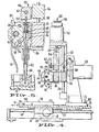
- Fig. 5 is an enlarged, sectional side view of the pipette assembly.
- Referring to Figure 1, an automatic liquid transfer machine includes two principle moving components, a horizontally translatable table 10 and a. vertically
translatable head assembly 12. As best illustrated in Fig. 4, the table 10 is mounted for horizontal translation on hardenedguide rods 14 by means ofslide bearings 16. Translation of the table is provided by astepper motor 18 through longitudinal drive means, which may include apinion 20 connected to the motor and arack 22 mounted on the underside of the table. Similarly, thehead 12 is mounted for vertical translation onguide rods 24 by means ofslide bearings 26. Translation of the head assembly is provided by astepper motor 28 through another longitudinal drive means, such aspinion 30 andrack 32. - The
head assembly 12 supports apipette assembly 34. This assembly includes asingle pipette 36 that is horizontally translatable in a direction transverse to the axis of translation of the table 10. The pipette is removably attached to the head assembly by means ofmounting blocks 38 and connectingpins 40, and moves vertically therewith. A plunger mechanism 42 is mounted on the head assembly for vertical movement relative to the pipette. The plunger mechanism inludes aplunger rod 44 disposed within thepipette 36. The rod is connected to anactuator bar 46 by means of aslide block 48. Thebar 46 is vertically translated alongguide rods 50 by means of astepper motor 52 andlead screw mechanism 54. - The added versatility which is afforded by the present invention arises from the fact that the
pipette assembly 34, in addition to moving vertically with thehead 12, can move horizontally in a direction transverse to the axis of translation of the table 10. Referring to Figures 2 and 3, asupport block 56 is disposed for horizontal translation along a pair ofguide rods 58 mounted between themounting blocks 38. Similarly, theslide block 48 on which theplunger rod 44 is mounted can translate along aguide rod 60 attached to theactuator bar 46. - The horiziontal translation of the
support block 56, and hence thepipette 36 mounted thereon, is effected by means of alead screw 62 driven by astepper motor 64. This motor can be supported on one of themounting blocks 38. Theslide block 48, which is connected to thesupport block 56 by theplunger rod 44, follows the horizontal translation of the support block. - As best illustrated in the detailed sectional diagram of Fig. 5, vertical translation of the
plunger rod 44 relative to the pipette nozzle section 35 changes the internal air volume of the bore of the pipette nozzle, causing fluid to be aspirated into or expelled. An air tight seal is provided between the rod and the top of the pipette nozzle by means of aseal ring 66, held by agrommet 68 and acompliance spring 70. The pipette nozzle 35 forms a piston section 72 which is reciprocable in a cylinder formed in thesupport block 56. Pipette nozzle 35 thereby restrained vertically by thespring 70 so that during a tip loading step, pipette nozzle 35 can slide vertically in theblock 56 against thecompliance spring 70. This allowsnose portion 82 of pipette nozzle 35 to reliably pick up tips of slightly different dimensions and to assure that the open ends of the tips are at the same elevation relative to the table 10 and a titer tray mounted thereon. - The table 10 includes two
work stations conventional titer tray 78 that includes a matrix arrangement of wells for housing liquid samples. Theother tray 80 at therear work station 76 can be a tip tray that contains a similar arrangement of receptacles that accommodate disposable pipette tips. A typical titer tray might contain 96 wells in a 12 x 8 matrix pattern. Preferably, thetray 78 can be accommodated at theforward work station 74 in a transverse orientation, or in the longitudinal direction of the table 10. - Referring again to the detailed side view of Fig. 5, the bottom or nose end, 82 of each pipette nozzle 35 is tapered or otherwise formed on its exterior surface so as to receive and frictionally engage the inner surface of a
disposable pipette tip 84. Such frictional engagement is to form an air tight seal therebetween. Atip 84 in a row of receptacles in thetip tray 80 is inserted onto and engages the end of thepipette 36 when thehead assembly 12 is lowered by thestepper motor 28 after the table 10 has brought one row oftips 84 into registry with the pipette. The walls of the receptacles in thetip tray 80 are arranged to center thetips 84 for engagement with thetapered end 82 of thepipette 36. - The subsequent removal of the
tip 84 from the pipette is accomplished with a tip ejector. The tip ejector includes abar 86 that is disposed between thesupport block 56 and the upper shoulder of thetip 84. Thebar 86 is connected to and supported by a pair of verticallytranslatable rods 88 mounted on thehead assembly 12. These rods are translated by means of a pair of drive means, such assolenoids 90 mounted on the top of the head assembly. When thesolenoids 90 are deactuated, theejector bar 86 is maintained in the upper position illustrated in Fig. 5. Actuation of the solenoids moves the bar vertically downward, to push thetip 84 down and release it from its frictional engagement with theend 82 of the pipette nozzle 35. A step motor and lead screw arrangement may be used as the drive means instead ofsolenoids 90, if desired. - To enable the machine to be used for filling operations as well as liquid transfers, a dispensing
tube 91 can be mounted on thesupport block 56. The end of this tube terminates at a well-defined location adjacent the end of thepipette 36. For example, it might be spaced forward of the pipette by a distance equal to the spacing between two wells in a microtiter tray. The remote end of thetube 91 is connected to a precision metering pump (not shown) which is in turn connected to a supply of reagents with which the wells are to be filled. - The operation of each of the
stepper motors solenoids 90, is controlled by asuitable microprocessor 92. Basically, themicroprocessor 92 functions to control the sequence of operations of each of these elements, and thus the interrelated movements of the table 10, thehead assembly 12, thepipette assembly 34 and thetip ejector bar 86 to effect transfer of liquid from one well in thetray 78 at theforward work station 74 to another well in that tray. Alternatively, a third work station can be provided on the table 10, and the transfer of liquid can occur between any well of either of two trays at the two work stations. Such asecond tray 98 is indicated in Fig. 4. Since the stepper motors provide a predetermined amount of rotation in response to each actuating signal applied thereto, accurate positioning of the movable elements can be obtained, for example, through appropriate control of the number or duration of actuating pulses, or other signals supplied by the microprocessor. - In addition to controlling these various movable elements, the
microprocessor 92 also monitors their movement through appropriately positioned sensors. For example, as shown in Figure 1, a sensor arrangement for the table 10 can include ablade 94 that is attached to and extends from the side of the table, and aposition sensor 96 that detects when theblade 94, and hence the table 10, passes through a predetermined reference point in its translation. Each time the table passes through this point, theposition sensor 96 sends a signal to themicroprocessor 92 that enables the microprocessor to update information relating to the table's position. Thus, if thestepper motor 18 should miss an actuating pulse during translation of the table, or if the pulse count stored within themicroprocessor 92 should not coincide with the position of the table, the error will not be carried over to successive cycles of operation. - In addition to the
reference sensor 96, a pair oflimit sensors 98 can be disposed at the respective ends of the path of travel of the table. A signal sent by these sensors indicates that the table is nearing the end of its travel, and provides an indication to themicroprocessor 92 to interrupt the supply of power to thestepper motor 18 or take some other such corrective action. Similar sensor arrangements can be provided to monitor the movement of thehead assembly 12, theactuator bar 46 and thesupport block 56. - In operation, the automatic liquid transfer machine basically functions to pick up a tip in the
tray 80, insert it in one of the wells in thetray 78, extract some of the liquid sample from this well, inject the tip into a reagent in another one of the wells, oscillate the plunger to mix the liquid, position the tip to expell all liquid and then return the tip to thetray 80, as disclosed in greater detail in the aforementioned application. - As mentioned previously, the instant invention provides an added degree of flexibility to this basic operation. Since the pipette is capable of moving in two perpendicular horizontal directions relative to the table 10, as well as vertically relative thereto, liquid can be transferred from any given well in the
tray 78 to any other well in that tray, and even to any well or receptacle in another tray on the table - It will be appreciated by those of ordinary skill in the art that the present invention can be embodied in other specific forms without departing from the spirit or essential characteristics thereof. The presently disclosed embodiment is therefore considered in all respects to be illustrative and not restrictive. For example, where the term "stepper" motor has been used to describe the preferred embodiment of the motor drive means for the table, head assembly and pipette assembly, it will be apparent that other precise positioning means may be used, such as direct current servo motors. The scope of the invention accordingly is indicated by the appended claims rather than the foregoing description, and all changes that come within the range of equivalence thereof are intended to be embraced therein.
Claims (10)
Priority Applications (1)
| Application Number | Priority Date | Filing Date | Title |
|---|---|---|---|
| AT84112253T ATE49059T1 (en) | 1983-10-14 | 1984-10-11 | BI-DIRECTIONAL SYSTEM FOR TRANSFER OF LIQUID SAMPLES. |
Applications Claiming Priority (2)
| Application Number | Priority Date | Filing Date | Title |
|---|---|---|---|
| US542113 | 1983-10-14 | ||
| US06/542,113 US4555957A (en) | 1983-10-14 | 1983-10-14 | Bi-directional liquid sample handling system |
Publications (2)
| Publication Number | Publication Date |
|---|---|
| EP0138205A1 true EP0138205A1 (en) | 1985-04-24 |
| EP0138205B1 EP0138205B1 (en) | 1989-12-27 |
Family
ID=24162391
Family Applications (1)
| Application Number | Title | Priority Date | Filing Date |
|---|---|---|---|
| EP84112253A Expired EP0138205B1 (en) | 1983-10-14 | 1984-10-11 | Bi-directional liquid sample handling system |
Country Status (11)
| Country | Link |
|---|---|
| US (1) | US4555957A (en) |
| EP (1) | EP0138205B1 (en) |
| JP (1) | JPS60111160A (en) |
| AT (1) | ATE49059T1 (en) |
| AU (1) | AU573761B2 (en) |
| CA (1) | CA1247064A (en) |
| DE (2) | DE138205T1 (en) |
| DK (1) | DK490884A (en) |
| FI (1) | FI844014L (en) |
| NO (1) | NO843765L (en) |
| NZ (1) | NZ209863A (en) |
Cited By (14)
| Publication number | Priority date | Publication date | Assignee | Title |
|---|---|---|---|---|
| EP0185330A2 (en) * | 1984-12-18 | 1986-06-25 | Cetus Corporation | Multi-sample liquid handling system |
| JPS61181968A (en) * | 1984-12-18 | 1986-08-14 | シタス コ−ポレイシヨン | Liquid treating system of large number of sample |
| EP0210014A2 (en) * | 1985-07-05 | 1987-01-28 | Cetus Corporation | Automated liquid handling apparatus and process with plate handler |
| WO1987006008A2 (en) * | 1986-03-26 | 1987-10-08 | Beckman Instruments, Inc. | Automated multi-purposse analytical chemistry processing center and laboratory work station |
| EP0243897A2 (en) * | 1986-05-02 | 1987-11-04 | MAPROTEC PROBENVERTEILSYSTEME FORSCHUNGS- & ENTWICKLUNGS KG | Samples distribution system |
| EP0246632A2 (en) * | 1986-05-21 | 1987-11-25 | Tosoh Corporation | Pipetting device having an automatic mechanism for replacing nozzle tips |
| EP0299519A2 (en) * | 1987-07-15 | 1989-01-18 | Fuji Photo Film Co., Ltd. | Biochemical analysis apparatus |
| EP0437906A1 (en) * | 1990-01-17 | 1991-07-24 | Minoru Atake | System for measuring liquid |
| US5104621A (en) * | 1986-03-26 | 1992-04-14 | Beckman Instruments, Inc. | Automated multi-purpose analytical chemistry processing center and laboratory work station |
| US5125748A (en) * | 1986-03-26 | 1992-06-30 | Beckman Instruments, Inc. | Optical detection module for use in an automated laboratory work station |
| US5169600A (en) * | 1987-07-15 | 1992-12-08 | Fuji Photo Film Co., Ltd. | Biochemical analysis apparatus for incubating and analyzing test sites on a long tape test film |
| US5358641A (en) * | 1989-10-27 | 1994-10-25 | Helena Laboratories Corporation | Column analyzer system and improved chromatograph column for use in the system |
| US6060022A (en) * | 1996-07-05 | 2000-05-09 | Beckman Coulter, Inc. | Automated sample processing system including automatic centrifuge device |
| GB2514185A (en) * | 2013-05-17 | 2014-11-19 | Stratec Biomedical Ag | Device and Method for Supplying Disposable Tips to a Pipetting System |
Families Citing this family (47)
| Publication number | Priority date | Publication date | Assignee | Title |
|---|---|---|---|---|
| US4554839A (en) * | 1983-10-14 | 1985-11-26 | Cetus Corporation | Multiple trough vessel for automated liquid handling apparatus |
| CA1286389C (en) * | 1986-04-17 | 1991-07-16 | Robert J. Sarrine | Automatic pipetting apparatus |
| JPS62299769A (en) * | 1986-06-20 | 1987-12-26 | Fuji Photo Film Co Ltd | Dispenser |
| US4873875A (en) * | 1986-06-27 | 1989-10-17 | Prism Technology, Inc. | System for optically interrogating liquid samples and for withdrawing selected sample portions |
| GR871619B (en) * | 1986-10-31 | 1988-03-03 | Genetic Systems Corp | Automated patient sample analysis instrument |
| JPH076998B2 (en) * | 1987-12-04 | 1995-01-30 | 富士写真フイルム株式会社 | Automatic dispenser and spotting method |
| US5012845A (en) * | 1988-08-18 | 1991-05-07 | Dynatech Precision Sampling Corporation | Fluid injector |
| US5463895A (en) * | 1990-11-09 | 1995-11-07 | Abbott Laboratories | Sample pipetting method |
| US5525302A (en) * | 1991-02-01 | 1996-06-11 | Astle; Thomas W. | Method and device for simultaneously transferring plural samples |
| US5312757A (en) * | 1991-05-02 | 1994-05-17 | Olympus Optical Co., Ltd. | Sample distributing method |
| JPH07128343A (en) * | 1993-11-04 | 1995-05-19 | Tosoh Corp | Pipette |
| US5531960A (en) * | 1994-11-28 | 1996-07-02 | Madison Metropolitan Sewerage District | Automated dissolved oxygen and biochemical oxygen demand analyzer |
| JP3630493B2 (en) * | 1995-03-20 | 2005-03-16 | プレシジョン・システム・サイエンス株式会社 | Liquid processing method and apparatus using dispenser |
| US5497670A (en) * | 1995-03-31 | 1996-03-12 | Carl; Richard A. | Liquid dispensing apparatus including means for loading pipette tips onto liquid dispensing cylinders and maintaining the loading force during the apparatus operation cycle |
| US5537880A (en) * | 1995-06-07 | 1996-07-23 | Abbott Laboratories | Automatic pipetting apparatus with leak detection and method of detecting a leak |
| US5723795A (en) * | 1995-12-14 | 1998-03-03 | Abbott Laboratories | Fluid handler and method of handling a fluid |
| US5915282A (en) * | 1995-12-14 | 1999-06-22 | Abbott Laboratories | Fluid handler and method of handling a fluid |
| US5965828A (en) * | 1995-12-14 | 1999-10-12 | Abbott Laboratories | Fluid handler and method of handling a fluid |
| US5697409A (en) * | 1996-02-21 | 1997-12-16 | Biomerieux Vitek, Inc. | Diluting and pipetting stations for sample testing machine |
| US6116099A (en) * | 1996-11-18 | 2000-09-12 | Carl; Richard A. | Liquid dispensing apparatus having means for loading pipette tips onto fluid dispensing cylinders |
| US20020159919A1 (en) * | 1998-01-09 | 2002-10-31 | Carl Churchill | Method and apparatus for high-speed microfluidic dispensing using text file control |
| US6063339A (en) * | 1998-01-09 | 2000-05-16 | Cartesian Technologies, Inc. | Method and apparatus for high-speed dot array dispensing |
| US7470547B2 (en) | 2003-07-31 | 2008-12-30 | Biodot, Inc. | Methods and systems for dispensing sub-microfluidic drops |
| DE69940490D1 (en) * | 1998-05-01 | 2009-04-09 | Gen Probe Inc | Automatic isolation and amplification method for a target nucleic acid sequence |
| DE19854919A1 (en) * | 1998-11-27 | 2000-06-15 | Luigs & Neumann Feinmechanik U | Work place for microbiological tests |
| AU3378600A (en) * | 1999-03-01 | 2000-09-21 | Glaxo Group Limited | Syringe array system and method |
| US6589791B1 (en) * | 1999-05-20 | 2003-07-08 | Cartesian Technologies, Inc. | State-variable control system |
| JP3426540B2 (en) * | 1999-07-12 | 2003-07-14 | 理学電機工業株式会社 | Analysis system with sample changer |
| US6177770B1 (en) * | 1999-09-14 | 2001-01-23 | Pharmacopeia, Inc. | Article comprising an incremental positioner |
| US6471917B1 (en) | 2000-04-11 | 2002-10-29 | Affymax, Inc. | System and method for single or multiple bead distribution with an adjustable capillary |
| DE10022693C1 (en) * | 2000-05-05 | 2001-10-11 | Cybio Instr Gmbh | Automatic pipetting system for filling microtiter plates has single row, multichannel head with mechanism for stripping nozzles from pipettes |
| EP1539352B1 (en) * | 2002-07-23 | 2009-12-23 | Protedyne Corporation | Liquid handling tool having hollow plunger |
| US6988518B2 (en) * | 2004-06-02 | 2006-01-24 | Automation Techniques, Inc. | Robotic system and method for transport of materials with minimization of footprint size |
| CA2512353A1 (en) * | 2004-07-16 | 2006-01-16 | Stemcell Technologies Inc. | Automated pipette machine |
| KR100624458B1 (en) * | 2005-01-17 | 2006-09-19 | 삼성전자주식회사 | Handheld centrifuge |
| DE102006034245C5 (en) * | 2006-07-21 | 2014-05-28 | Stratec Biomedical Systems Ag | Positioning device for positioning pipettes |
| WO2008089449A2 (en) | 2007-01-19 | 2008-07-24 | Biodot, Inc. | Systems and methods for high speed array printing and hybridization |
| US20110009608A1 (en) * | 2008-04-09 | 2011-01-13 | Bioneer Corporation | Automatic refining apparatus, multi-well plate kit and method for extracting hexane from biological samples |
| US9103782B2 (en) | 2008-12-02 | 2015-08-11 | Malvern Instruments Incorporated | Automatic isothermal titration microcalorimeter apparatus and method of use |
| DE102010005722A1 (en) | 2010-01-26 | 2011-07-28 | Eppendorf AG, 22339 | Positioning device for a sample distribution device, sample distribution device with positioning device and method for positioning |
| US8367022B2 (en) * | 2010-05-03 | 2013-02-05 | Integra Biosciences Corp. | Unintended motion control for manually directed multi-channel electronic pipettor |
| DK2665557T3 (en) | 2011-01-21 | 2020-04-06 | Biodot Inc | Piezoelectric dispenser with a longitudinal transducer and interchangeable capillary tube |
| DE102011108537B4 (en) | 2011-07-26 | 2023-10-12 | Eppendorf Se | Positioning device for a laboratory device for distributing fluid samples and laboratory device with positioning device |
| CN106554901B (en) * | 2015-09-30 | 2019-06-14 | 精专生医股份有限公司 | The board of automatization abstraction nucleic acid and the syringe for cooperating it to use |
| US10144537B2 (en) | 2016-11-30 | 2018-12-04 | Mallinckrodt Nuclear Medicine Llc | Systems and methods for dispensing radioactive liquids |
| US20210247411A1 (en) * | 2020-02-10 | 2021-08-12 | Funai Electric Co., Ltd. | Maintenance Reservoir |
| CN114428013A (en) * | 2022-01-18 | 2022-05-03 | 杨力 | Reagent mixing preparation device for geological detection |
Citations (8)
| Publication number | Priority date | Publication date | Assignee | Title |
|---|---|---|---|---|
| FR2123593A5 (en) * | 1971-01-14 | 1972-09-15 | Commissariat Energie Atomique | Device for taking up and depositing solns - esp for x-ray analysis |
| US3772154A (en) * | 1971-05-03 | 1973-11-13 | Technicon Instr | Method and apparatus for automated antibiotic susceptibility analysis of bacteria samples |
| US3831618A (en) * | 1972-12-22 | 1974-08-27 | Abbott Lab | Apparatus for the precision metering of fluids |
| FR2323184A1 (en) * | 1975-09-05 | 1977-04-01 | Ibm | Test sample container manipulation system - has magazine containing test tubes transported to given position using belt conveyor system |
| FR2446480A1 (en) * | 1979-01-10 | 1980-08-08 | Instruments Sa | Sampling and preparation of biological liquids - using microprocessor to control sampling and injection of rinsing water |
| US4265855A (en) * | 1978-11-03 | 1981-05-05 | Electro-Nucleonics, Inc. | System for performing immunochemical and other analyses involving phase separation |
| EP0042337A1 (en) * | 1980-06-16 | 1981-12-23 | EASTMAN KODAK COMPANY (a New Jersey corporation) | Method and apparatus for metering biological fluids |
| EP0052006A1 (en) * | 1980-11-10 | 1982-05-19 | Hitachi, Ltd. | Automatic chemical analyzer |
Family Cites Families (14)
| Publication number | Priority date | Publication date | Assignee | Title |
|---|---|---|---|---|
| US3143393A (en) * | 1959-06-18 | 1964-08-04 | Luc Donald De Seguin Des Hons | Apparatus for automatically performing chemical operations and similar or related operations |
| US3687632A (en) * | 1969-07-30 | 1972-08-29 | Rohe Scientific Corp | System for transferring liquids between containers |
| US3912456A (en) * | 1974-03-04 | 1975-10-14 | Anatronics Corp | Apparatus and method for automatic chemical analysis |
| US4076503A (en) * | 1974-08-22 | 1978-02-28 | The Perkin-Elmer Corporation | Pipetting system for use in kinetic analysis apparatus and the like |
| US4036381A (en) * | 1975-09-05 | 1977-07-19 | International Business Machines Corporation | Apparatus for transferring sample holders relative to a movable magazine |
| JPS5269383A (en) * | 1975-12-05 | 1977-06-09 | Hitachi Ltd | Dispenser for multiple item analysis |
| LU77642A1 (en) * | 1976-07-09 | 1977-10-03 | ||
| US4299796A (en) * | 1977-04-22 | 1981-11-10 | Vitatron Scientific B.V. | Apparatus for performing tests and measurements on liquid samples |
| JPS5467492A (en) * | 1977-11-09 | 1979-05-30 | Yasunobu Tsukioka | Titrating device |
| JPS54111892A (en) * | 1978-02-17 | 1979-09-01 | Ii Mairusu Rooton | Method and device for inspecting numerous data |
| JPS56142460A (en) * | 1980-04-08 | 1981-11-06 | Toshiba Corp | Automatic chemical analyzing device |
| US4340390A (en) * | 1980-06-16 | 1982-07-20 | Eastman Kodak Company | Method and apparatus for metering biological fluids |
| JPS5885168A (en) * | 1981-11-16 | 1983-05-21 | Toshiba Corp | Automatic chemical analyzer |
| US4478094A (en) * | 1983-01-21 | 1984-10-23 | Cetus Corporation | Liquid sample handling system |
-
1983
- 1983-10-14 US US06/542,113 patent/US4555957A/en not_active Expired - Lifetime
-
1984
- 1984-08-29 CA CA000462034A patent/CA1247064A/en not_active Expired
- 1984-09-20 NO NO843765A patent/NO843765L/en unknown
- 1984-10-11 DE DE198484112253T patent/DE138205T1/en active Pending
- 1984-10-11 EP EP84112253A patent/EP0138205B1/en not_active Expired
- 1984-10-11 DE DE8484112253T patent/DE3480874D1/en not_active Expired - Fee Related
- 1984-10-11 AT AT84112253T patent/ATE49059T1/en not_active IP Right Cessation
- 1984-10-12 DK DK490884A patent/DK490884A/en not_active Application Discontinuation
- 1984-10-12 AU AU34180/84A patent/AU573761B2/en not_active Ceased
- 1984-10-12 NZ NZ209863A patent/NZ209863A/en unknown
- 1984-10-12 FI FI844014A patent/FI844014L/en not_active Application Discontinuation
- 1984-10-15 JP JP59214478A patent/JPS60111160A/en active Pending
Patent Citations (8)
| Publication number | Priority date | Publication date | Assignee | Title |
|---|---|---|---|---|
| FR2123593A5 (en) * | 1971-01-14 | 1972-09-15 | Commissariat Energie Atomique | Device for taking up and depositing solns - esp for x-ray analysis |
| US3772154A (en) * | 1971-05-03 | 1973-11-13 | Technicon Instr | Method and apparatus for automated antibiotic susceptibility analysis of bacteria samples |
| US3831618A (en) * | 1972-12-22 | 1974-08-27 | Abbott Lab | Apparatus for the precision metering of fluids |
| FR2323184A1 (en) * | 1975-09-05 | 1977-04-01 | Ibm | Test sample container manipulation system - has magazine containing test tubes transported to given position using belt conveyor system |
| US4265855A (en) * | 1978-11-03 | 1981-05-05 | Electro-Nucleonics, Inc. | System for performing immunochemical and other analyses involving phase separation |
| FR2446480A1 (en) * | 1979-01-10 | 1980-08-08 | Instruments Sa | Sampling and preparation of biological liquids - using microprocessor to control sampling and injection of rinsing water |
| EP0042337A1 (en) * | 1980-06-16 | 1981-12-23 | EASTMAN KODAK COMPANY (a New Jersey corporation) | Method and apparatus for metering biological fluids |
| EP0052006A1 (en) * | 1980-11-10 | 1982-05-19 | Hitachi, Ltd. | Automatic chemical analyzer |
Cited By (24)
| Publication number | Priority date | Publication date | Assignee | Title |
|---|---|---|---|---|
| JPS61181968A (en) * | 1984-12-18 | 1986-08-14 | シタス コ−ポレイシヨン | Liquid treating system of large number of sample |
| EP0185330A3 (en) * | 1984-12-18 | 1987-01-07 | Cetus Corporation | Multi-sample liquid handling system |
| EP0185330A2 (en) * | 1984-12-18 | 1986-06-25 | Cetus Corporation | Multi-sample liquid handling system |
| EP0210014A2 (en) * | 1985-07-05 | 1987-01-28 | Cetus Corporation | Automated liquid handling apparatus and process with plate handler |
| EP0210014A3 (en) * | 1985-07-05 | 1987-10-14 | Cetus Corporation | Automated liquid handling apparatus and process with plate handler |
| WO1987006008A2 (en) * | 1986-03-26 | 1987-10-08 | Beckman Instruments, Inc. | Automated multi-purposse analytical chemistry processing center and laboratory work station |
| WO1987006008A3 (en) * | 1986-03-26 | 1987-11-05 | Beckman Instruments Inc | Automated multi-purposse analytical chemistry processing center and laboratory work station |
| US5125748A (en) * | 1986-03-26 | 1992-06-30 | Beckman Instruments, Inc. | Optical detection module for use in an automated laboratory work station |
| US5104621A (en) * | 1986-03-26 | 1992-04-14 | Beckman Instruments, Inc. | Automated multi-purpose analytical chemistry processing center and laboratory work station |
| EP0243897A3 (en) * | 1986-05-02 | 1989-03-15 | MAPROTEC PROBENVERTEILSYSTEME FORSCHUNGS- & ENTWICKLUNGS KG | Samples distribution system |
| EP0243897A2 (en) * | 1986-05-02 | 1987-11-04 | MAPROTEC PROBENVERTEILSYSTEME FORSCHUNGS- & ENTWICKLUNGS KG | Samples distribution system |
| AU590418B2 (en) * | 1986-05-21 | 1989-11-02 | Tosoh Corporation | Pipetting device having an automatic mechanism for replacing nozzle tips |
| EP0246632A3 (en) * | 1986-05-21 | 1988-07-20 | Tosoh Corporation | Pipetting device having an automatic mechanism for replacing nozzle tips |
| EP0246632A2 (en) * | 1986-05-21 | 1987-11-25 | Tosoh Corporation | Pipetting device having an automatic mechanism for replacing nozzle tips |
| EP0299519A2 (en) * | 1987-07-15 | 1989-01-18 | Fuji Photo Film Co., Ltd. | Biochemical analysis apparatus |
| EP0299519A3 (en) * | 1987-07-15 | 1989-11-15 | Fuji Photo Film Co., Ltd. | Biochemical analysis apparatus |
| US5169600A (en) * | 1987-07-15 | 1992-12-08 | Fuji Photo Film Co., Ltd. | Biochemical analysis apparatus for incubating and analyzing test sites on a long tape test film |
| US5358641A (en) * | 1989-10-27 | 1994-10-25 | Helena Laboratories Corporation | Column analyzer system and improved chromatograph column for use in the system |
| US5589063A (en) * | 1989-10-27 | 1996-12-31 | Helena Laboratories Corporation | Column analyzer system and improved chromatograph column for use in the system |
| US5595664A (en) * | 1989-10-27 | 1997-01-21 | Helena Laboratories Corporation | Column analyzer system and improved chromatograph column for use in the system |
| EP0437906A1 (en) * | 1990-01-17 | 1991-07-24 | Minoru Atake | System for measuring liquid |
| US6060022A (en) * | 1996-07-05 | 2000-05-09 | Beckman Coulter, Inc. | Automated sample processing system including automatic centrifuge device |
| US8038942B2 (en) | 1996-07-05 | 2011-10-18 | Beckman Coulter, Inc. | Automated sample processing system |
| GB2514185A (en) * | 2013-05-17 | 2014-11-19 | Stratec Biomedical Ag | Device and Method for Supplying Disposable Tips to a Pipetting System |
Also Published As
| Publication number | Publication date |
|---|---|
| AU3418084A (en) | 1985-04-18 |
| DK490884D0 (en) | 1984-10-12 |
| JPS60111160A (en) | 1985-06-17 |
| CA1247064A (en) | 1988-12-20 |
| FI844014A0 (en) | 1984-10-12 |
| US4555957A (en) | 1985-12-03 |
| DE138205T1 (en) | 1986-01-16 |
| AU573761B2 (en) | 1988-06-23 |
| NZ209863A (en) | 1988-01-08 |
| DE3480874D1 (en) | 1990-02-01 |
| DK490884A (en) | 1985-04-15 |
| EP0138205B1 (en) | 1989-12-27 |
| NO843765L (en) | 1985-04-15 |
| ATE49059T1 (en) | 1990-01-15 |
| FI844014L (en) | 1985-04-15 |
| US4555957B1 (en) | 1987-12-22 |
Similar Documents
| Publication | Publication Date | Title |
|---|---|---|
| US4555957A (en) | Bi-directional liquid sample handling system | |
| EP0114686B1 (en) | Liquid sample handling system | |
| EP0140247B1 (en) | Multiple trough vessel for automated liquid handling apparatus | |
| US11524287B2 (en) | Automatic pipetting device for transferring samples and/or reagents and method for transferring liquid samples and/or reagents | |
| US5525515A (en) | Process of handling liquids in an automated liquid handling apparatus | |
| DE69224685T2 (en) | Automatic analyzer for samples | |
| US7541001B2 (en) | Automatic pipetting and analyzing device | |
| EP0246632B1 (en) | Pipetting device having an automatic mechanism for replacing nozzle tips | |
| US4039288A (en) | Automatic chemical testing apparatus incorporating improved conveyor system | |
| US4844868A (en) | Automatic chemical analysis reagent distribution and analysis apparatus | |
| US6371331B1 (en) | Electronic apparatus for dispensing precise small quantities of fluid | |
| US20020104389A1 (en) | Automated liquid handling device | |
| DE3736632A1 (en) | AUTOMATIC ANALYSIS DEVICE FOR PATIENT SAMPLES | |
| WO1987006008A2 (en) | Automated multi-purposse analytical chemistry processing center and laboratory work station | |
| EP0037578A2 (en) | Discrete type automated chemical analytic apparatus | |
| JPH0579944B2 (en) | ||
| CA1144462A (en) | Discrete type automated chemical analytic apparatus | |
| EP1206321B1 (en) | Flexible pipette strip and method of its use | |
| EP0042337B1 (en) | Method and apparatus for metering biological fluids | |
| WO2020142798A1 (en) | Pipetting device and method for the transfer of fluids | |
| WO1988000707A1 (en) | Liquid handling station | |
| JPS5951357A (en) | Automatic biochemical analyzer | |
| JPS5931455A (en) | Automatic biochemical analysis device | |
| AT522107A4 (en) | Pipetting device | |
| JPS5940257A (en) | Reaction tube exchange apparatus in biochemical automatic analytical apparatus |
Legal Events
| Date | Code | Title | Description |
|---|---|---|---|
| PUAI | Public reference made under article 153(3) epc to a published international application that has entered the european phase |
Free format text: ORIGINAL CODE: 0009012 |
|
| AK | Designated contracting states |
Designated state(s): AT BE CH DE FR GB IT LI NL SE |
|
| ITCL | It: translation for ep claims filed |
Representative=s name: BARZANO' E ZANARDO ROMA S.P.A. |
|
| 17P | Request for examination filed |
Effective date: 19850802 |
|
| EL | Fr: translation of claims filed | ||
| TCNL | Nl: translation of patent claims filed | ||
| TCAT | At: translation of patent claims filed | ||
| DET | De: translation of patent claims | ||
| 17Q | First examination report despatched |
Effective date: 19861110 |
|
| D17Q | First examination report despatched (deleted) | ||
| ITF | It: translation for a ep patent filed | ||
| GRAA | (expected) grant |
Free format text: ORIGINAL CODE: 0009210 |
|
| AK | Designated contracting states |
Kind code of ref document: B1 Designated state(s): AT BE CH DE FR GB IT LI NL SE |
|
| REF | Corresponds to: |
Ref document number: 49059 Country of ref document: AT Date of ref document: 19900115 Kind code of ref document: T |
|
| REF | Corresponds to: |
Ref document number: 3480874 Country of ref document: DE Date of ref document: 19900201 |
|
| ET | Fr: translation filed | ||
| PG25 | Lapsed in a contracting state [announced via postgrant information from national office to epo] |
Ref country code: GB Effective date: 19901011 Ref country code: AT Effective date: 19901011 |
|
| PG25 | Lapsed in a contracting state [announced via postgrant information from national office to epo] |
Ref country code: SE Effective date: 19901012 |
|
| PLBE | No opposition filed within time limit |
Free format text: ORIGINAL CODE: 0009261 |
|
| STAA | Information on the status of an ep patent application or granted ep patent |
Free format text: STATUS: NO OPPOSITION FILED WITHIN TIME LIMIT |
|
| PG25 | Lapsed in a contracting state [announced via postgrant information from national office to epo] |
Ref country code: LI Effective date: 19901031 Ref country code: CH Effective date: 19901031 Ref country code: BE Effective date: 19901031 |
|
| 26N | No opposition filed | ||
| BERE | Be: lapsed |
Owner name: CETUS CORP. Effective date: 19901031 |
|
| PG25 | Lapsed in a contracting state [announced via postgrant information from national office to epo] |
Ref country code: NL Effective date: 19910501 |
|
| GBPC | Gb: european patent ceased through non-payment of renewal fee | ||
| NLV4 | Nl: lapsed or anulled due to non-payment of the annual fee | ||
| PG25 | Lapsed in a contracting state [announced via postgrant information from national office to epo] |
Ref country code: FR Effective date: 19910628 |
|
| REG | Reference to a national code |
Ref country code: CH Ref legal event code: PL |
|
| PG25 | Lapsed in a contracting state [announced via postgrant information from national office to epo] |
Ref country code: DE Effective date: 19910702 |
|
| REG | Reference to a national code |
Ref country code: FR Ref legal event code: ST |
|
| EUG | Se: european patent has lapsed |
Ref document number: 84112253.4 Effective date: 19910603 |