EP0137285A1 - Verfahren zur Mengenmessung von strömenden Medien und Messeinrichtung zur Durchführung dieses Verfahrens - Google Patents
Verfahren zur Mengenmessung von strömenden Medien und Messeinrichtung zur Durchführung dieses Verfahrens Download PDFInfo
- Publication number
- EP0137285A1 EP0137285A1 EP84110341A EP84110341A EP0137285A1 EP 0137285 A1 EP0137285 A1 EP 0137285A1 EP 84110341 A EP84110341 A EP 84110341A EP 84110341 A EP84110341 A EP 84110341A EP 0137285 A1 EP0137285 A1 EP 0137285A1
- Authority
- EP
- European Patent Office
- Prior art keywords
- measuring
- measurement
- measuring device
- time
- overflow
- Prior art date
- Legal status (The legal status is an assumption and is not a legal conclusion. Google has not performed a legal analysis and makes no representation as to the accuracy of the status listed.)
- Withdrawn
Links
- 238000000034 method Methods 0.000 title claims description 11
- 239000012530 fluid Substances 0.000 title 1
- 238000005259 measurement Methods 0.000 claims abstract description 44
- XLYOFNOQVPJJNP-UHFFFAOYSA-N water Substances O XLYOFNOQVPJJNP-UHFFFAOYSA-N 0.000 claims abstract description 19
- 238000012360 testing method Methods 0.000 claims description 13
- 238000011088 calibration curve Methods 0.000 claims description 10
- 239000002351 wastewater Substances 0.000 claims description 3
- WHXSMMKQMYFTQS-UHFFFAOYSA-N Lithium Chemical compound [Li] WHXSMMKQMYFTQS-UHFFFAOYSA-N 0.000 claims description 2
- 229910052744 lithium Inorganic materials 0.000 claims description 2
- 230000003111 delayed effect Effects 0.000 claims 1
- 238000001514 detection method Methods 0.000 abstract description 2
- 238000010586 diagram Methods 0.000 description 5
- 238000002604 ultrasonography Methods 0.000 description 5
- 239000010865 sewage Substances 0.000 description 4
- 238000011156 evaluation Methods 0.000 description 3
- 238000012545 processing Methods 0.000 description 2
- 230000001960 triggered effect Effects 0.000 description 2
- 230000015572 biosynthetic process Effects 0.000 description 1
- 239000003990 capacitor Substances 0.000 description 1
- 238000004140 cleaning Methods 0.000 description 1
- 230000000052 comparative effect Effects 0.000 description 1
- 239000004020 conductor Substances 0.000 description 1
- 238000010276 construction Methods 0.000 description 1
- 238000005260 corrosion Methods 0.000 description 1
- 230000007797 corrosion Effects 0.000 description 1
- 230000008878 coupling Effects 0.000 description 1
- 238000010168 coupling process Methods 0.000 description 1
- 238000005859 coupling reaction Methods 0.000 description 1
- 238000004880 explosion Methods 0.000 description 1
- 238000011010 flushing procedure Methods 0.000 description 1
- 230000006698 induction Effects 0.000 description 1
- 238000009434 installation Methods 0.000 description 1
- 230000010354 integration Effects 0.000 description 1
- 230000007774 longterm Effects 0.000 description 1
- 238000012423 maintenance Methods 0.000 description 1
- 230000001681 protective effect Effects 0.000 description 1
- 238000000746 purification Methods 0.000 description 1
- 239000000126 substance Substances 0.000 description 1
- 238000012546 transfer Methods 0.000 description 1
- 230000007704 transition Effects 0.000 description 1
- 238000005406 washing Methods 0.000 description 1
- 238000003911 water pollution Methods 0.000 description 1
Images

Classifications
-
- G—PHYSICS
- G01—MEASURING; TESTING
- G01F—MEASURING VOLUME, VOLUME FLOW, MASS FLOW OR LIQUID LEVEL; METERING BY VOLUME
- G01F1/00—Measuring the volume flow or mass flow of fluid or fluent solid material wherein the fluid passes through a meter in a continuous flow
- G01F1/002—Measuring the volume flow or mass flow of fluid or fluent solid material wherein the fluid passes through a meter in a continuous flow wherein the flow is in an open channel
- G01F1/005—Measuring the volume flow or mass flow of fluid or fluent solid material wherein the fluid passes through a meter in a continuous flow wherein the flow is in an open channel using floats
-
- G—PHYSICS
- G01—MEASURING; TESTING
- G01F—MEASURING VOLUME, VOLUME FLOW, MASS FLOW OR LIQUID LEVEL; METERING BY VOLUME
- G01F15/00—Details of, or accessories for, apparatus of groups G01F1/00 - G01F13/00 insofar as such details or appliances are not adapted to particular types of such apparatus
- G01F15/06—Indicating or recording devices
- G01F15/061—Indicating or recording devices for remote indication
- G01F15/063—Indicating or recording devices for remote indication using electrical means
Definitions
- the invention relates to a method for measuring the quantity of flowing media of the type specified by claim 1 and to a measuring device for carrying out this method according to the type according to claim 5.
- DE-AS 10 96 254 describes a measuring device of the type specified, in which the permanent magnet actuation of the electrical sensor contacts designed as protective gas contacts triggers direct analog displays for the different level heights detected with each sensor contact on a height scale of the measuring device, by which a drive axis of the permanent magnet driven by the float is passed through.
- the special feature of a metric is the gear coupling of the drive axis of the permanent magnet to two further drive axes for two further permanent magnets, in the path of which further electrical encoder contacts are arranged Subdivision of the individual measuring stages into cm, dm and m dimensions realized.
- a quantity measurement of flowing media is currently of interest for use in municipal rain overflow systems, which are designed underground either as a separate sewer system or as a mixed sewer system with closed flushing channels, via which the waste water collected by means of rain channel shafts opening on the street side is discharged to a sewage treatment plant.
- Municipal rain overflow systems which are designed underground either as a separate sewer system or as a mixed sewer system with closed flushing channels, via which the waste water collected by means of rain channel shafts opening on the street side is discharged to a sewage treatment plant.
- the measuring principle implemented with such measuring devices is based on analog processing of measured values continuously determined by means of a special measuring head for the level of the flowing medium changing at a measuring location, the analog processing including linearization and integration of the measured values, through the digitization of which the water flows are then reduced
- a measurement volume predetermined for the measurement location usually also in the formation of an assigned measurement overflow channel, can be calculated directly by a computer.
- the invention characterized by the claims solves the problem of designing a method for measuring the quantity of flowing media and a measuring device for carrying out this method according to the type specified in such a way that it is particularly useful for getting to know the inflow quantities, which in the case of municipal rain overflow systems, are formed by a measuring overflow channel Measurement site can be measured, direct measurement results can be obtained, the accuracy of which is at least approximately comparable with the degree of accuracy that can be achieved, for example, with an ultrasound measuring device.
- the advantages that can be achieved with the invention are essentially that by additionally taking into account a time factor for the previously known digital measuring principle of a level height measurement carried out with a float, the time-related count values thus obtained instead of metric count values only have to be simply multiplied by a calculation quantity which are predetermined for the measurement stages recorded digitally with these count values.
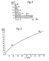
- this calculation variable will be the water flow occurring at the maximum level of each measuring stage, which can be read directly from a calibration curve of the measuring overflow channel.
- the measuring principle modified with this additional consideration of a time factor also results in the additional possibility that is particularly desired for this application, with only a small additional expenditure on equipment and therefore correspondingly cost-saving also to obtain information about the overflow duration and the overflow frequency, so that taking into account, for example, all Measured values are determined one year and measures can be precisely programmed, which can be used to precisely set a desired water value in the chemical and biological cleaning stages at a sewage treatment plant and / or with which, alternatively, measures can be taken in good time to prevent water pollution.
- the above formula thus gives, for example, the calibration curve, graphically represented in FIG. 5, of a test channel, from which it can thus be directly read that, for example, a measured height of 20 cm or 50 cm, a current water flow of 0.39 or 1.65 m 3 / s through the alluvial channel connected to the test channel.
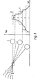
- the measurement curve A shown in FIG. 1 for the level height is converted into individual digital measurement stages 1 to 5 by means of a float C pivotably mounted at the measurement location above the maximum level height B.
- a float C pivotably mounted at the measurement location above the maximum level height B.
- an electrical sensor contact 11 to 15 is assigned to each measuring stage.
- All encoder contacts are connected to each other with an arrangement in a common switching level by means of a cascade connection, with an encapsulated embodiment with a housing being expediently provided to achieve adequate corrosion and explosion protection of the arrangement, which housing, in addition to the rotary bearing of the float, is provided at the foot of the test channel Canal shaft can be attached.
- the mutual distance between the individual encoder contacts should be adjusted for differently specified calibration curves and also for the possibility of further subdivision of the individual digital measuring stages up to a corresponding number n along an adjustment scale for being able to precisely set the assigned sensor contact in tabular form / for each measured value desired for a certain level.
- the electrical sensor contacts 11 to 15 can be actuated in a contactless manner by means of a permanent magnet which can be moved by the float C and which is designed as a segment of a circle which is arranged concentrically to its pivot axis. As long as the level is moving within the digital measuring stage 1, only the assigned sensor contact 11 is therefore actuated by this permanent magnet, while when changing to the next digital measuring stage 2, the contact 12 of the latter is additionally actuated. Only when the maximum level B is reached are all existing encoder contacts 11 to 15 actuated.
- the electrical sensor contacts 11, 12, 13 .... n are connected to a mains-independent battery supply 20, with lithium batteries preferably being provided for this purpose, since this type of battery can best withstand the robust measurement conditions prevailing in a rain overflow system.
- the cascade connection of these encoder contacts is clocked in a preselectable time cycle by a common square-wave pulse oscillator 21 of a measuring device connected via a cable connection, which is arranged within the dirt trap on the street-side mouth of the manhole closed with a manhole cover.
- a common square-wave pulse oscillator 21 of a measuring device connected via a cable connection, which is arranged within the dirt trap on the street-side mouth of the manhole closed with a manhole cover.
- These digital time displays 22 therefore cumulatively convey total time counts for the digital measuring stages assigned to them in the form of an electrical pulse count triggered by the sensor contacts, which should optimally experience a time-delayed forwarding at each measuring stage by a delay element 23 in the form of a monostable multivibrator, in order to do so to protect the battery supply 20.
- Such delay elements 23 also have the purpose that only brief fluctuations in the level at the transition between two successive measuring stages do not result in an undesired display for the evaluation of the measurement results for the higher-ranking measuring stage and instead there is an indication for the lower-ranking measuring stage until the arrival of the next counting pulse remains.
- Verzögerun sgliedern g 23 may be controlled in the forwarding of counts equal for all digital time display 22, or advantageously, different delay so that, for example, a count of the sensed with the sensor contact 11 measuring stage 1 for a time t 1 corresponds to, for example, five minutes , while a count value of the following measuring stage 2 detected with the sensor contact 12 corresponds to a time T 1 of, for example, one minute with a differentiated reading option on the assigned digital time displays 22.
- the individual sensor contacts are optimally still connected to individual digital event displays 24 of the measuring device, with which the time counter values obtained at each measuring stage are counted as event counter values for an event display separate from the digital time displays 22.
- the connection to these event displays 24 is carried out via the delay elements 23 and an AND element 25 assigned in each case such that the digital time display 22 of the respectively assigned measuring stage connected to the output of each AND element only then simultaneously with the associated event display 24
- the respective count value is triggered when the time pulse predetermined by the rectangular pulse oscillator 21 is momentarily released by the delay element 23 assigned to the relevant measuring stage.
- the assigned sensor contact 11 Only if, for example in measurement stage 1, the assigned sensor contact 11 remains actuated longer than the relevant delay time T 1 of five minutes, are the corresponding total time and event counts passed on to the two associated displays 22 and 24, while each shorter actuation this one encoder contact 11 is disregarded for display.
- the values that can be read from the calibration curve of the measurement raid channel can also be optimally stored for this calculation in a computer, for which a connection option is then expediently provided on the measuring device of the above-described measuring device in order to be able to take over the information from the digital display devices 22 and the event displays 24 directly .
- the electronic circuit of the measuring device described above with reference to FIG. 2 also includes other components, such as, in particular, capacitors, resistors, switching transistors and diodes which, as ballasts, are intended to ensure low power consumption.
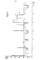
- the measurement protocol shown in FIG. 3 was obtained.
- the measuring device was there Equipped with six electrical encoder contacts for subdivision of the measurement curve A into six digital measurement stages in the level heights 0.5, 10, 20, 35 and 45 cm.
- An equally clocked delay t 1 to t 6 of 30 s was specified for each measuring stage.
- the plotter diagram shown in dashed line D in FIG. 4 and otherwise continued over the entire period of time was obtained for the ultrasound measuring device used in parallel. 3, the graphical evaluation of the measurement protocol according to FIG.
Landscapes
- Physics & Mathematics (AREA)
- Fluid Mechanics (AREA)
- General Physics & Mathematics (AREA)
- Measuring Volume Flow (AREA)
- Testing Or Calibration Of Command Recording Devices (AREA)
Applications Claiming Priority (2)
| Application Number | Priority Date | Filing Date | Title |
|---|---|---|---|
| DE3332473 | 1983-09-08 | ||
| DE19833332473 DE3332473A1 (de) | 1983-09-08 | 1983-09-08 | Verfahren und einrichtung zur messung einer wechselnden pegelhoehe |
Publications (1)
| Publication Number | Publication Date |
|---|---|
| EP0137285A1 true EP0137285A1 (de) | 1985-04-17 |
Family
ID=6208579
Family Applications (1)
| Application Number | Title | Priority Date | Filing Date |
|---|---|---|---|
| EP84110341A Withdrawn EP0137285A1 (de) | 1983-09-08 | 1984-08-30 | Verfahren zur Mengenmessung von strömenden Medien und Messeinrichtung zur Durchführung dieses Verfahrens |
Country Status (2)
| Country | Link |
|---|---|
| EP (1) | EP0137285A1 (esLanguage) |
| DE (1) | DE3332473A1 (esLanguage) |
Cited By (1)
| Publication number | Priority date | Publication date | Assignee | Title |
|---|---|---|---|---|
| FR2630208A1 (fr) * | 1988-04-18 | 1989-10-20 | Paris Rhin Rhone Autoroutes | Dispositif pour la mesure d'un niveau de liquide, notamment d'un niveau d'eau courante |
Families Citing this family (1)
| Publication number | Priority date | Publication date | Assignee | Title |
|---|---|---|---|---|
| US4754641A (en) * | 1987-02-10 | 1988-07-05 | Schlumberger Technology Corporation | Method and apparatus for measurement of fluid flow in a drilling rig return line |
Citations (4)
| Publication number | Priority date | Publication date | Assignee | Title |
|---|---|---|---|---|
| DE2418860A1 (de) * | 1974-04-19 | 1975-10-30 | Kuebler Impulsgeraete | Messwertgeber fuer fuellstandsanzeige von fluessigkeiten |
| GB1430772A (en) * | 1972-10-04 | 1976-04-07 | Instrumentation Specialties Co | Flow meter |
| US4127030A (en) * | 1977-10-12 | 1978-11-28 | Martig Jr Kenneth W | Flow measurement |
| USRE29868E (en) * | 1973-07-27 | 1978-12-19 | Manning Environmental Corporation | Fluid flow measuring system and method |
Family Cites Families (4)
| Publication number | Priority date | Publication date | Assignee | Title |
|---|---|---|---|---|
| DE1096254B (de) * | 1959-07-23 | 1960-12-29 | Siemens Ag | Gebereinrichtung zur Fernuebertragung der Winkelstellung einer Achse |
| DE2053954A1 (de) * | 1970-11-03 | 1972-05-18 | Werner & Pfleiderer | Vorrichtung zur Überwachung und Anzeige eines Flüssigkeitsstandes |
| DE2314363C3 (de) * | 1973-03-22 | 1978-03-30 | Reaktiva Szoevetkezet, Budapest | Magnetischer Verschiebungsfühler insbesondere für Pegelstandsmesser mit Schwimmer |
| DE2935015A1 (de) * | 1979-08-30 | 1981-03-12 | Trauernicht, Rudolf, 2961 Spetzerfehn | Verfahren und einrichtung zur ermittlung des durchflusses offener gerinne. |
-
1983
- 1983-09-08 DE DE19833332473 patent/DE3332473A1/de active Granted
-
1984
- 1984-08-30 EP EP84110341A patent/EP0137285A1/de not_active Withdrawn
Patent Citations (4)
| Publication number | Priority date | Publication date | Assignee | Title |
|---|---|---|---|---|
| GB1430772A (en) * | 1972-10-04 | 1976-04-07 | Instrumentation Specialties Co | Flow meter |
| USRE29868E (en) * | 1973-07-27 | 1978-12-19 | Manning Environmental Corporation | Fluid flow measuring system and method |
| DE2418860A1 (de) * | 1974-04-19 | 1975-10-30 | Kuebler Impulsgeraete | Messwertgeber fuer fuellstandsanzeige von fluessigkeiten |
| US4127030A (en) * | 1977-10-12 | 1978-11-28 | Martig Jr Kenneth W | Flow measurement |
Cited By (1)
| Publication number | Priority date | Publication date | Assignee | Title |
|---|---|---|---|---|
| FR2630208A1 (fr) * | 1988-04-18 | 1989-10-20 | Paris Rhin Rhone Autoroutes | Dispositif pour la mesure d'un niveau de liquide, notamment d'un niveau d'eau courante |
Also Published As
| Publication number | Publication date |
|---|---|
| DE3332473C2 (esLanguage) | 1987-07-23 |
| DE3332473A1 (de) | 1985-03-28 |
Similar Documents
| Publication | Publication Date | Title |
|---|---|---|
| EP2130002B1 (de) | VERFAHREN ZUM BETREIBEN EINES MAGNETISCH-INDUKTIVEN DURCHFLUßMEßGERÄTS | |
| DE2459224A1 (de) | Durchfluss- und zeitproportionales probenahme- und messystem | |
| EP0137285A1 (de) | Verfahren zur Mengenmessung von strömenden Medien und Messeinrichtung zur Durchführung dieses Verfahrens | |
| EP1060132B1 (de) | Verfahren zur steuerung von biologischen abwasserkläranlagen | |
| EP2206914B1 (de) | Verfahren zum Betrieb einer Wasserkraftwerksanlage | |
| DE102011113541A1 (de) | Messvorrichtung für Wasserzähler und Verfahren zum Betreiben einer batteriebetriebenen Messvorrichtung | |
| Moody et al. | Vegetative treatment systems for open feedlot runoff: project design and monitoring methods for five commercial beef feedlots | |
| EP3855147A1 (de) | Energiezähler und verfahren zur erfassung einer wärme- oder kältemenge | |
| DE4016373A1 (de) | Verfahren zur ueberwachung eines kanalisationsnetzes | |
| Whitaker et al. | Channel modification and macroinvertebrate community diversity in small streams 1 | |
| DE1291523B (de) | Induktiver Durchflussmesser fuer Fluessigkeiten in offenen Kanaelen oder Gerinnen, insbesondere in Abwasserkanaelen | |
| Moin | Evaluating the benefits of near-continuous monitoring, real-time control, and SCM visibility in performance of stormwater control measures | |
| DE3329215A1 (de) | Anordnung zur messung der differenzhoehe zwischen zwei wasserspiegeln | |
| DE19858314C2 (de) | Anlage zur zentralen Erfassung der Durchflußmenge con Abwässern | |
| DE19601646C1 (de) | Meßanordnung zur Abflußmessung | |
| DE102017125296B3 (de) | Verfahren zur Ermittlung der hydraulischen Durchlässigkeit eines Filters und Filteranlage mit einem hydraulischen Filter | |
| DE102024102480B4 (de) | Ermitteln eines Verstopfungszustands einer Dachrinne | |
| DE1773251B2 (de) | Meßgerät für Flüssigkeitsstände | |
| DE10130221C1 (de) | Einrichtung zum Messen, Kontrollieren und Analysieren von Abwasser | |
| DE3347606A1 (de) | Anordnung und verfahren zum messen eines fluessigkeitspegels | |
| AT507673B1 (de) | Verfahren zum betrieb von wasserkraftwerksanlagen | |
| DE102020133121B4 (de) | Verfahren und Vorrichtung zur Überlaufmessung einer Flüssigkeit über eine Überlaufkante eines Beckens | |
| DE3050838C2 (esLanguage) | ||
| Daniel et al. | Assessing the pollutional load from nonpoint sources: Planning considerations and a description of an automated water quality monitoring program | |
| DE102022111701A1 (de) | Verfahren zur Überwachung eines Behandlungsbauwerks für Niederschlagswasser und Behandlungsbauwerk für Niederschlagswasser |
Legal Events
| Date | Code | Title | Description |
|---|---|---|---|
| PUAI | Public reference made under article 153(3) epc to a published international application that has entered the european phase |
Free format text: ORIGINAL CODE: 0009012 |
|
| AK | Designated contracting states |
Designated state(s): AT BE CH DE FR GB IT LI LU NL SE |
|
| RTI1 | Title (correction) | ||
| 17P | Request for examination filed |
Effective date: 19851015 |
|
| 17Q | First examination report despatched |
Effective date: 19870204 |
|
| STAA | Information on the status of an ep patent application or granted ep patent |
Free format text: STATUS: THE APPLICATION IS DEEMED TO BE WITHDRAWN |
|
| 18D | Application deemed to be withdrawn |
Effective date: 19870616 |
|
| RIN1 | Information on inventor provided before grant (corrected) |
Inventor name: KNOPF, FRANZ |