EP0137211B1 - Absorption type heat transfer system functioning as a temperature pressure potential amplifier - Google Patents
Absorption type heat transfer system functioning as a temperature pressure potential amplifier Download PDFInfo
- Publication number
- EP0137211B1 EP0137211B1 EP84109558A EP84109558A EP0137211B1 EP 0137211 B1 EP0137211 B1 EP 0137211B1 EP 84109558 A EP84109558 A EP 84109558A EP 84109558 A EP84109558 A EP 84109558A EP 0137211 B1 EP0137211 B1 EP 0137211B1
- Authority
- EP
- European Patent Office
- Prior art keywords
- solute
- temperature
- solution
- absorber
- vapor
- Prior art date
- Legal status (The legal status is an assumption and is not a legal conclusion. Google has not performed a legal analysis and makes no representation as to the accuracy of the status listed.)
- Expired
Links
- 238000010521 absorption reaction Methods 0.000 title claims abstract description 23
- 238000012546 transfer Methods 0.000 title abstract description 26
- 239000006096 absorbing agent Substances 0.000 claims abstract description 110
- 239000002904 solvent Substances 0.000 claims abstract description 25
- 239000003507 refrigerant Substances 0.000 claims description 54
- 238000004821 distillation Methods 0.000 claims description 41
- 238000001704 evaporation Methods 0.000 claims description 13
- 238000010438 heat treatment Methods 0.000 claims description 8
- 150000001298 alcohols Chemical class 0.000 claims description 5
- 150000008282 halocarbons Chemical class 0.000 claims description 2
- 239000002798 polar solvent Substances 0.000 claims description 2
- 239000012530 fluid Substances 0.000 abstract description 41
- 239000007788 liquid Substances 0.000 abstract description 40
- 230000002745 absorbent Effects 0.000 abstract description 32
- 239000002250 absorbent Substances 0.000 abstract description 32
- 238000009835 boiling Methods 0.000 abstract description 15
- BDERNNFJNOPAEC-UHFFFAOYSA-N propan-1-ol Chemical compound CCCO BDERNNFJNOPAEC-UHFFFAOYSA-N 0.000 description 38
- NPNPZTNLOVBDOC-UHFFFAOYSA-N 1,1-difluoroethane Chemical compound CC(F)F NPNPZTNLOVBDOC-UHFFFAOYSA-N 0.000 description 31
- VOPWNXZWBYDODV-UHFFFAOYSA-N Chlorodifluoromethane Chemical compound FC(F)Cl VOPWNXZWBYDODV-UHFFFAOYSA-N 0.000 description 21
- 238000005381 potential energy Methods 0.000 description 17
- XLYOFNOQVPJJNP-UHFFFAOYSA-N water Substances O XLYOFNOQVPJJNP-UHFFFAOYSA-N 0.000 description 17
- 238000000926 separation method Methods 0.000 description 14
- 238000001816 cooling Methods 0.000 description 13
- 238000009834 vaporization Methods 0.000 description 13
- 230000008016 vaporization Effects 0.000 description 13
- 238000004378 air conditioning Methods 0.000 description 10
- 239000012071 phase Substances 0.000 description 10
- 230000003321 amplification Effects 0.000 description 9
- 230000008020 evaporation Effects 0.000 description 9
- 238000000034 method Methods 0.000 description 9
- 238000003199 nucleic acid amplification method Methods 0.000 description 9
- 230000008569 process Effects 0.000 description 9
- LRHPLDYGYMQRHN-UHFFFAOYSA-N N-Butanol Chemical compound CCCCO LRHPLDYGYMQRHN-UHFFFAOYSA-N 0.000 description 8
- PXBRQCKWGAHEHS-UHFFFAOYSA-N dichlorodifluoromethane Chemical compound FC(F)(Cl)Cl PXBRQCKWGAHEHS-UHFFFAOYSA-N 0.000 description 8
- 235000019404 dichlorodifluoromethane Nutrition 0.000 description 8
- 230000005484 gravity Effects 0.000 description 8
- 238000005086 pumping Methods 0.000 description 7
- BHNZEZWIUMJCGF-UHFFFAOYSA-N 1-chloro-1,1-difluoroethane Chemical compound CC(F)(F)Cl BHNZEZWIUMJCGF-UHFFFAOYSA-N 0.000 description 6
- 238000009833 condensation Methods 0.000 description 6
- 230000005494 condensation Effects 0.000 description 6
- 238000005057 refrigeration Methods 0.000 description 6
- 238000004891 communication Methods 0.000 description 4
- 230000006835 compression Effects 0.000 description 4
- 238000007906 compression Methods 0.000 description 4
- 238000010586 diagram Methods 0.000 description 4
- 230000001939 inductive effect Effects 0.000 description 4
- 239000004338 Dichlorodifluoromethane Substances 0.000 description 3
- 230000001143 conditioned effect Effects 0.000 description 3
- 229940042935 dichlorodifluoromethane Drugs 0.000 description 3
- 230000001965 increasing effect Effects 0.000 description 3
- 238000004519 manufacturing process Methods 0.000 description 3
- 239000000203 mixture Substances 0.000 description 3
- 238000010926 purge Methods 0.000 description 3
- 230000002441 reversible effect Effects 0.000 description 3
- LFQSCWFLJHTTHZ-UHFFFAOYSA-N Ethanol Chemical compound CCO LFQSCWFLJHTTHZ-UHFFFAOYSA-N 0.000 description 2
- 230000008859 change Effects 0.000 description 2
- 238000006243 chemical reaction Methods 0.000 description 2
- 238000006073 displacement reaction Methods 0.000 description 2
- AMXOYNBUYSYVKV-UHFFFAOYSA-M lithium bromide Chemical compound [Li+].[Br-] AMXOYNBUYSYVKV-UHFFFAOYSA-M 0.000 description 2
- 238000011084 recovery Methods 0.000 description 2
- 230000001105 regulatory effect Effects 0.000 description 2
- AMQJEAYHLZJPGS-UHFFFAOYSA-N N-Pentanol Chemical compound CCCCCO AMQJEAYHLZJPGS-UHFFFAOYSA-N 0.000 description 1
- 238000009825 accumulation Methods 0.000 description 1
- 239000008186 active pharmaceutical agent Substances 0.000 description 1
- 238000004364 calculation method Methods 0.000 description 1
- 239000003795 chemical substances by application Substances 0.000 description 1
- 238000002485 combustion reaction Methods 0.000 description 1
- 238000010276 construction Methods 0.000 description 1
- 238000005516 engineering process Methods 0.000 description 1
- 230000001747 exhibiting effect Effects 0.000 description 1
- 239000003673 groundwater Substances 0.000 description 1
- 230000006872 improvement Effects 0.000 description 1
- 230000010354 integration Effects 0.000 description 1
- 239000007791 liquid phase Substances 0.000 description 1
- 229940059936 lithium bromide Drugs 0.000 description 1
- 230000004048 modification Effects 0.000 description 1
- 238000012986 modification Methods 0.000 description 1
- 239000003415 peat Substances 0.000 description 1
- 229920000642 polymer Polymers 0.000 description 1
- 230000009467 reduction Effects 0.000 description 1
- 230000000087 stabilizing effect Effects 0.000 description 1
- 238000003860 storage Methods 0.000 description 1
- 230000002459 sustained effect Effects 0.000 description 1
- 238000012360 testing method Methods 0.000 description 1
Images


Classifications
-
- F—MECHANICAL ENGINEERING; LIGHTING; HEATING; WEAPONS; BLASTING
- F01—MACHINES OR ENGINES IN GENERAL; ENGINE PLANTS IN GENERAL; STEAM ENGINES
- F01K—STEAM ENGINE PLANTS; STEAM ACCUMULATORS; ENGINE PLANTS NOT OTHERWISE PROVIDED FOR; ENGINES USING SPECIAL WORKING FLUIDS OR CYCLES
- F01K25/00—Plants or engines characterised by use of special working fluids, not otherwise provided for; Plants operating in closed cycles and not otherwise provided for
- F01K25/06—Plants or engines characterised by use of special working fluids, not otherwise provided for; Plants operating in closed cycles and not otherwise provided for using mixtures of different fluids
- F01K25/065—Plants or engines characterised by use of special working fluids, not otherwise provided for; Plants operating in closed cycles and not otherwise provided for using mixtures of different fluids with an absorption fluid remaining at least partly in the liquid state, e.g. water for ammonia
-
- F—MECHANICAL ENGINEERING; LIGHTING; HEATING; WEAPONS; BLASTING
- F25—REFRIGERATION OR COOLING; COMBINED HEATING AND REFRIGERATION SYSTEMS; HEAT PUMP SYSTEMS; MANUFACTURE OR STORAGE OF ICE; LIQUEFACTION SOLIDIFICATION OF GASES
- F25B—REFRIGERATION MACHINES, PLANTS OR SYSTEMS; COMBINED HEATING AND REFRIGERATION SYSTEMS; HEAT PUMP SYSTEMS
- F25B15/00—Sorption machines, plants or systems, operating continuously, e.g. absorption type
- F25B15/02—Sorption machines, plants or systems, operating continuously, e.g. absorption type without inert gas
-
- Y—GENERAL TAGGING OF NEW TECHNOLOGICAL DEVELOPMENTS; GENERAL TAGGING OF CROSS-SECTIONAL TECHNOLOGIES SPANNING OVER SEVERAL SECTIONS OF THE IPC; TECHNICAL SUBJECTS COVERED BY FORMER USPC CROSS-REFERENCE ART COLLECTIONS [XRACs] AND DIGESTS
- Y02—TECHNOLOGIES OR APPLICATIONS FOR MITIGATION OR ADAPTATION AGAINST CLIMATE CHANGE
- Y02A—TECHNOLOGIES FOR ADAPTATION TO CLIMATE CHANGE
- Y02A30/00—Adapting or protecting infrastructure or their operation
- Y02A30/27—Relating to heating, ventilation or air conditioning [HVAC] technologies
-
- Y—GENERAL TAGGING OF NEW TECHNOLOGICAL DEVELOPMENTS; GENERAL TAGGING OF CROSS-SECTIONAL TECHNOLOGIES SPANNING OVER SEVERAL SECTIONS OF THE IPC; TECHNICAL SUBJECTS COVERED BY FORMER USPC CROSS-REFERENCE ART COLLECTIONS [XRACs] AND DIGESTS
- Y02—TECHNOLOGIES OR APPLICATIONS FOR MITIGATION OR ADAPTATION AGAINST CLIMATE CHANGE
- Y02B—CLIMATE CHANGE MITIGATION TECHNOLOGIES RELATED TO BUILDINGS, e.g. HOUSING, HOUSE APPLIANCES OR RELATED END-USER APPLICATIONS
- Y02B30/00—Energy efficient heating, ventilation or air conditioning [HVAC]
- Y02B30/62—Absorption based systems
Definitions
- This invention relates to a thermally powered absorption system and the needed working fluids, comprising a low boiling point solute and a high boiling point solvent, for producing useful heat transfer or its power equivalent.
- Absorption type air conditioning and refrigeration system of the prior art have some aspects in common with this invention; but the fluid pairs for working fluids and the system chosen for prior art absorption type air conditioning and refrigeration cycles do not exhibit temperature pressure potential amplification as illustrated in Figure 1.
- prior art absorption cycles employ heat flow at the high temperature region to power the cycle rather than heat flow at the low temperature region to power the cycle of the system. For instance, see Patent No. 4,009,575. Another example of a prior art system is shown in U.S. Patent No. 2,932,958, which relates to a heat pump.
- the device in this invention discloses the basic system of separating the refrigerating fluid from an agent, and an absorbing process in a different part of the system to produce heat.
- Document WO-82/00958 discloses an absorption type heat transfer system using lithium-bromide solution and water as working fluids. Due to the low temperature gradient of vapor pressure of this fluid system, the energy demand for separation of absorbant and absorbed fluid is too high to allow for further improvement of thermodynamic output.
- solute vapor is absorbed in a high temperature absorber from which heat of absorption is released. More specifically, at the low temperature region of the cycle, solute vapor is removed by evaporation from a solution of a solute and a solvent within a low temperature sensor means, and such solute vapor that is separated is condensed to a liquid in a low temperature condenser means to thus establish a temperature and/or vapor pressure potential difference between the condensed solute and the remaining concentrated solution in the separator.
- vapor pressure potential difference is meant vapor pressure difference between vapor in equilibrium with the two fluids times the specific volume of the vapor.
- the mutual solubility of the working fluids, solute and solvent is so limited at the low temperature region that the resulting solution has a vapor pressure approaching that of the separated solute; then as the temperature of the working fluids increases, the vapor pressure of the solution must increase less rapidly than the vapor pressure of the separated solute and Raoult's law is approached.
- the mutual solubility of the solute and solvent is greater at high temperatures than at low temperatures as indicated by the slope of the curve, plotted for the vapor pressure of the solution on a logarithm scale versus temperature, being less steep than the corresponding slope of the curve plotting vapor pressure versus temperature for the pure solvent. (See Figure 1).
- the percent solution in all examples means weight percent of low boiling point solute in solution.
- the working fluids thus chosen permit separation of solute from solution by distillation by using a small amount of energy or a small temperature difference between the separator and the condenser at low temperatures. At high temperatures the vapor pressure of the separated solute is so increased over that of the remaining concentrated solution that there is an amplified pressure potential difference that can be recovered when the vaporized solute is reabsorbed into solution.
- means is provided such as a counter-flow heat exchanger also provides means for cooling diluted solution returning to the low temperature region.
- the separated liquid solute is delivered to a boiler means where evaporation takes place, and a delivery means delivers the resulting solute vapor to a higher temperature absorber with associated heat exchange means which receives the heated concentrated solution, all of which provides means for recovering the amplified temperature and/or pressure potential difference to accomplish useful output in the form of heat transfer or its mechanical equivalent.
- the amplified pressure potential difference of the vaporized solute with respect to the vapor pressure potential of the solution within an absorber can either drive a power converter, such as a turbine or a positive displacer as illustrated, or the corresponding amplified temperature difference can be used more directly for heat transfer such as a distillation process for separating useful distillates, or for heat pumping for space heating or air conditioning.
- the heat of vaporization of the refrigerant atthe higher temperature is so near the value of the heat of absorption of the vapor into solution that most useful free energy recovered as power must be replaced into the high temperature boiler in the form of make up heat from an external source.
- External heat may also be applied to the counter-flow heat exchanger, in which case the temperature of the external heat source fluid may be drawn down to near ambient temperature.
- net heat absorbed at the low temperature separator may be recovered at the absorber for power conversion at the high temperature.
- an absorption type system functioning as a temperature, pressure potential amplifier and having separating means and absorber
- the separating means including a condenser, an evaporative separator containing a solution of solute in a solvent and means for delivering separated solute vapor to the condenser; heat exchanger means; boiler means disposed for receiving and evaporating condensed solute; means for recovering the amplified temperature and/or vapor pressure potential difference generated between the absorber and the boiler means; means for returning the solution to the evaporative separator; characterized in that the solution comprises a relatively non-polar volatile refrigerant solute such as halocarbon refrigerants in a strong polar solvent such as alcohols, and that heating means separate from said potential difference recovering means are provided, said heating means being associated with said boiler means or said absorber and having an output temperature higher than that of the evaporative separator for maintaining said absorber at a stable higher temperature than the evaporative separator.
- the means for delivering the separated refrigerant solute vapor to the condenser includes a power driven blower.
- the heat exchange means for raising the temperature of the remaining solution includes a counter-flow heat exchanger, and the means for returning the diluted solution within the absorber to the evaporative separator also includes a counter-flow heat exchanger.
- the system includes a distillation boiler thermally associated with the absorber and a distillation condenser connected with the distillation boiler and thermally associated with the boiler means.
- the means for maintaining the absorber at a higher temperature than the separator means may include a mechanically driven heat pump means in association with the evaporative separator and with the absorber to cause the flow of solute vapor from the evaporative separator to the absorber to thus maintain the absorber at the higher temperature and the evaporative separator at the lower temperature.
- the means for recovering the amplified temperature and/or pressure potential difference generated between the absorber and the boiler means includes a vapor driven converter.
- Figure 1 shows the comparison between the vapor pressure data at various temperatures for a solution of 60% difluoroethane (R-152a) dissolved in the polar liquid n-propanol versus the data for vapor pressure for pure difluoroethane (R-152a). Percent numbers all mean weight percent.
- Figure 1 illustrates the required but typical difference in slope between the data curve of the pressure of pure refrigerant solutes and the vapor pressure data curves for the class of solutions disclosed as working fluids in the following descriptions. Vapor pressures are plotted according to a logarithm vertical scale.
- the two rectangles in the lower portion of Figure 1 are engine indicator diagrams by which one can calculate available mechanical energy for one pound of vaporized solute moving from the pure liquid phase to the solution phase.
- the first engine indicator diagram is for calculating the available pressure potential energy (Joule (Btu)) at the indicated low temperature; the second engine indicator diagram is for calculating the amplified pressure potential energy for one pound of solute vapor at the higher temperature region.
- a temperature pressure potential amplifier system such as illustrated in Figure 2 makes use of temperature difference between solute and solution arising from unusual vapor pressure versus temperature relations appearing in the illustrated family of binary liquids, one illustration of which is the refrigerant difluoroethane (R-152a) which serves as the low boiling point solute in a high boiling point solvent of n-propanol.
- R-152a refrigerant difluoroethane
- Table 1 Some of the data is plotted in Figure 1.
- Refrigerant difluoroethane in N-Propanol Vapor pressures in 10 3 Pa (pounds per square inch (Psia)) versus temperature in °C (Deg. F).
- the heat of vaporization h v of R-152a is 305.9 ⁇ 10 3 joule/kg (131.4 Btu/lb) at -1°C (30 Deg. F), 297.5x10 3 joule/kg (127.8 Btu) at 10°C (50 Deg. F), 257.2 ⁇ 10 3 joules/kg (110.5 Btu) at 46.1°C (115 Deg. F) and 234.9x10 3 joules/kg (100.9 Btu) at 60°C (140 Deg. F).
- Vapor pressure of refrigerant difluoroethane (R-152a) in mixed alcohol solvent showing temperature and/or pressure potential amplification.
- the free pressure potential energy, PE, of Table 1 is approximately the specific volume, v, of the solute vapor multiplied by the pressure difference between that of pure solute and of solution expressed in pounds per square foot. To convert to Btu units one must further divide by 778 ft. Ibs./Btu. Thus in the case of one pound of R-152a separated from 44.4 wt.% solution at -1.1°C at (30 Deg. F) the free pressure potential energy is calculated to be 0.74x10 3 Joule (0.70 Btu); whereas at a temperature of 48.9°C (120 Deg. F) the calculated free pressure potential energy is amplified to 3.17x10 3 Joule (3 Btu) and at 60°C (140 Deg. F) to 3.64x10 3 Joule (3.45 Btu).
- Figure 1 incorporates published and additionally measured data from Table 1 to illustrate the phenomenon of temperature and/or pressure potential amplification in the case of R-152a and its solution in n-propanol. How this phenomenon may be employed in various system embodiments to yield highly useful results will be explained separately in succeeding Figures 2 through 6.
- the vapor pressure of pure solute and of solution with various percentages of solute are plotted as sloping lines with a vertical logarythm scale against a horizontal scale of temperature in degrees F.
- R-152a is plotted with its vapor pressure to represent the solute, and the vapor pressure of the solution is represented by 68 wt.% R-152a (and 32 wt.% n-propanol).
- Table 3 is the vapor pressure data for monochlorodifluoromethane (R-22) and for three concentrations of R-22 in alcohol solution.
- the 50% solution of R-22 in n-propanol is a very good concentration of solution for heat pumping. The more concentrated solutions are better if power is to be produced.
- Potential energies can be calculated in Btu per pound of solute by knowing the specific volume of the vapor.
- the vapor pressures of the pure R-22 and the corresponding specific volumes are published data. The vapor pressures are measured in pounds per square inch absolute.
- the fluid vapor pressures for two concentrations of R-22 in n-propanol solution and another 66 percent concentration of R-22 in n-butanol are recorded to illustrate suitable fluids for two different manifestations of the energy output from a system such as that of Figure 5.
- the first manifestation is that of a heat pump with a likely water supply at 10°C (50 Deg. F) in which weight percent R-22 in n-propanol is best. Vapor from this solution at 10°C (50 Deg. F) will condense at -4.4°C (24 Deg. F) or lower. Then the vapor from separated R-22 is at sufficient pressure at 10°C (50 Deg.
- difluoroethane (152a) of Table 1 may be mixed with the non-flammable dichloro-difluoromethane (R-12) to eliminate flammability, or refrigerant R-115 as tabulated in Table 7 may well be used.
- Pressure data were taken with a mixture 26.2 wt.% R-152a and 73.8 wt.% R-12, which mixed refrigerant is commonly designated as refrigerant R-500.
- the following Table 5 shows observed vapor pressures of a solution of 54.5 wt.% R-500 in N-Propanol. This data discloses temperature and/or vapor pressure potential difference amplification as the temperature is increased.
- the Table 6 shows comparable pressure versus temperature data for R-12 dissolved in N-Propanol.
- This invention is thus a three fold cooperation of: (a) Suitable solute and solvent of widely differing boiling points exhibiting large temperature sensitive divergence from Raoult's Principle as shown by difference in slope of the vapor pressure curves of respective solute and solution; (b) Suitable cycles to provide useful heat transfer or power output from amplified temperature and/or vapor pressure potential difference at the higher operating temperatures resulting from greater divergence from Raoult's Principle at lower temperatures; and (c) Suitable mechanical systems to bring about the required cycles of temperature and pressure changes of the working fluids to thereby deliver amplified useful heat transfer or equivalent power output at the higher temperature.
- the two rectangular enclosures in the lower portion represent the complete cycle of operation of R-152a vapor from n-propanol solution of Table 1 when plotting enthalpy change, H v , of R-152a according to the vertical scale of the right.
- the circled numbers represent phases of the cycle of operation which will be discussed.
- Phase 1 represents evaporation of a pound of refrigerant solute from the solution at a low temperature, in this example 4.4°C (40 Deg. F), 277.8°K (500 Deg. R).
- Heat of vaporization, H v which is the enthalpy change for a pound of vapor, is plotted by the height of the rectangle as indicated on the vertical scale.
- the temperature difference Delta t equals 1.7°C (3 Deg. F) Phase 2, that of condensation of pure solute, takes place at the temperature of 2.8°C (37 Deg. F) and in the process releases heat of vaporization, 301.9x10 3 Joule/kg (129.7 Btu/pound).
- the solute is then raised in temperature to 46.1°C (115 Deg. F) 319.4°K (575 Deg. R) by passing through a counter-flow heat exchanger.
- Phase 3 consists of evaporation of pure solute at this higher temperature with absorption of 257.2x10 3 Joule/kg (110.5 Btu) of heat.
- the temperature difference of this horizontal line Delta t is 8.3°C (15 Deg. F). Note the amplification of 1.7°C (3 Deg. F) to 8.3°C (15 Deg. F).
- the solution in this example has been raised to a temperature of 54.4°C (130 Deg. F) by a counter flow heat exchanger.
- Phase 4 consists of absorbing the solute vapor and liberating the heat of absorption, 111 Btu per pound.
- the temperature of the diluted solution is brought back to the original 4.4°C (40 Deg. F) by the counter flow heat exchanger.
- the potential energy, P.E., that can be converted to useful work is determined by dividing the area of each phase rectangle by the temperature degrees R. It is seen that more energy can be converted to useful work by any engine cycle with phases differing 8.3°C (15 Deg. F) between the boiler and the condenser or the equivalent absorber than by a cycle operating with temperature difference of but 1.7°C (3 Deg. F) between the evaporating and condensing phases.
- the potential for deriving useful work is thus seen to have been amplified by changing the cycle from the low temperature range to the higher temperature range and by reversing its order of phases to thus make a complete cycle.
- the results must be reduced to Btu units if its numerical value is to be compared approximately equal to that of the previous thermal calculation.
- the above plotted area must be divided by 778 ft. Ibs./Btu.
- the above plotted area is referred to as an engine indicator diagram.
- arrows designate the direction of fluid flow.
- V designates vapor refrigerant solute
- VD designates vaporized distillate
- L designates liquid refrigerant solute
- CS designates concentrated absorbent solution (a solution in which there may still be a greater proportion of solute than of solvent)
- DS designates diluted solution in which there is a larger proportion of refrigerant solute than in the case of CS.
- W designates water or other heat exchange fluid supplied externally.
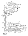
- the distillation system 20 which illustrates a teaching of this invention, and in which most of the thermal power for distillation is derived from heat flow at a low ambient temperature region including a low temperature separator 101.
- the distillation system 20 includes the low temperature separator 101 for separating a suitable low boiling point solute refrigerant from a diluted absorbent solution as received from a supply duct 102.
- the proper liquid level within the low temperature separator 101 is maintained with the aid of a liquid level control means 103.
- Low temperature heat which would normally be useless in a state of the art distillation system, is supplied to the separator 101 from an ambient source by means of a heat exchanger 104 to thus maintain the separator 101 at a predetermined temperature.
- the concentrated and therefore activated absorbent solution leaves the separator 101 by means of a concentrated solution conduit 109 while the separated solute refrigerant vapor passes through a low temperature vapor conduit 110 to a low temperature condenser 113 where the refrigerant vapor is condensed back to a liquid, thus establishing a temperature and/or vapor pressure potential difference between the condensed solute and the concentrated solution remaining in the separator 101.
- this temperature and/or vapor pressure potential difference is nearly entirely temperature difference, as the pressure difference between the separator 101 and the condenser 113 is very small.
- a heat exchanger 114 for circulating cold water is provided as a heat sink as a means for maintaining the low temperature condenser 113 at a lower temperature than the temperature of the separator 101.
- the free energy involved in the separation of refrigerant solute from solution is now temperature potential (stored) energy in the distillation system 20.
- the heat released in condensing the refrigerant vapor is rejected to the low temperature environment by the heat exchanger 114, and the liquid refrigerant is removed from the condenser 113 through a liquid solute conduit 115 by means of gravity and a solute pump 116.
- concentrated absorbent solution is removed from the separator 101 by means of gravity and a solution pump means 117, while diluted absorbent solution is admitted to the separator 101 by a flow regulating means 118, which may be combined with the pump means 117.
- the fluid conduits 102, 109 and 115 are in thermal contact in a counter-flow heat exchange means 120 for raising the temperature of the separated refrigerant solute and the remaining concentrated solution, thus amplifying the temperature and/or vapor pressure potential difference between the condensed solute and the remaining concentrated solution.
- the counter-flow heat exchange means 120 also includes a heat supply conduit 122 for providing a flow of externaly heated water or other fluid to provide make up heat to replace any heat lost in the heat exchange means 120.
- the solute conduit 115 terminates at a high temperature solute boiler 124 including a liquid level control means 126, and a residue purging means 127 for correcting any accumulation of high boiling point solvent in the solute boiler 124, and a boiler heat exchanger 128 which is in thermal association with the boiler 124 and which can supply additional make up heat from a suitable external source to replace heat loss that might occur in the high temperature solute boiler 124, and thus provide means to maintain and stabilize a high temperature absorber 138 at a higher temperature than the separator 101.
- the components of the high temperature region including the solute boiler 124 and the absorber 138 should be well insulated.
- a hot vapor solute conduit 134 provides a passage means from the solute boiler 124 to the absorber 138 which receives heated concentrated absorbent solution from the conduit 109 through a distributor means 139.
- the means for recovering the amplified temperature and/or vapor pressure potential difference (in this case amplified temperature difference) generated between the absorber 138 and the boiler 124 includes a distillation boiler 140, which is disposed in thermal association with the absorber 138 for distilling a fluid mixture which is delivered through a liquid outlet 143.
- a vapor conduit 144 provided to carry distilled vapor and its heat content from the distillation boiler 140 to a distillation condenser 145 disposed within and thermally associated with the solute boiler 124 for condensing the desired distillate and for transmitting the released heat of condensation to the refrigerant solute within the boiler 124.
- the distillation condenser 145 is also included in this recovery means.
- the desired distillate is recovered from the distiiiation condenser 145 through a distillate from the distillation condenser 145 through a distillate discharge means 146.
- the vapor solute conduit 134 may enter the absorber 138 at the bottom, thus allowing solute vapor to bubble through the absorbent solution within the absorber 138 to aid absorption.
- the distributor means 139 is not required at the terminal end of the conduit 109.
- the counter-flow heat exchanger 120 also provides means for cooling diluted solution leaving the absorber 138 to near the temperature of the separator 101 to which it is returning.
- Dilute solution of a low boiling point solute such as a refrigerant
- a high boiling point solvent such as tabulated in Tables 1 through 5
- dilute solution is meant a solution with a relatively large percent of refrigerant solute.
- Low temperature heat for maintaining the separator 101 at a predetermined low temperature and for evaporating solute from solution within the separator 101 is supplied by available cold water flowing through the heat exchanger 104.
- Vapor produced in the separator 101 passes through the low temperature vapor conduit 110 into the low temperature condenser 113 where it is condensed to a liquid.
- the condenser 113 is maintained at a temperature lower than the temperature in the separator 101 by colder water flowing through the heat exchanger 114.
- Cold dilute absorbent solution is delivered to the separator 101 through the flow regulator 118.
- the concentrated absorbent solution is pumped out of the separator 101 through the conduit 109 by the solution pump means 117 assisted by gravity, while the cold condensed solute is pumped from the condenser 113 through the conduit 115 by the solution pump means 116 assisted by gravity.
- Both fluids are heated in the counter-flow heat exchanger 120 by warm diluted solution returning in the reverse direction through the conduit 102 of the heat exchanger 120 thus cooling the diluted solution and amplifying the temperature and/or vapor pressure potential difference between the heated fluids. Any additionally need heat is supplied by warm water, such as geothermal water, also flowing in the reverse direction through the external heat supply conduit 122.
- Heated solute from the conduit 115 enters the solute boiler 124 to maintain it at a level as determined by the liquid level control means 126, and the make up heat needed from an external source to maintain and stabilize the absorber 138 at a higher temperature than the separator 101 is added to the solute boiler 124 by the heat exchanger 128, and evaporation of solute takes place in the solute boiler 124.
- Most of the heat for evaporation of the solute within the boiler 124 is supplied by the condensation of distillate taking place in the distillation condenser 145.
- the vaporized solute passes from the solute boiler 124 through the conduit 134 and into the absorber 138 where it is absorbed into the concentrated solution flowing over the surface of the distillation boiler 140, and the resulting heat of condensation and absorption is transmitted to the liquid within the distillation boiler 140.
- the distillation boiler 140 is thermally associated with the absorber 138 for recovering the heat of absorption from the absorber 138.
- the distillation boiler 140 is serviced with fresh liquid by the liquid inlet 142 and the residue is removed through the outlet 143. Vapor produced in the distillation boiler 140 passes through the vapor conduit 144 into the distillation condenser 145, carrying its heat of vaporization with it.
- distillation condenser 145 As this vapor is condensed in the distillation condenser 145 its heat of vaporization is transmitted back to the liquid in the solute boiler 124. Condensed distillate is recovered through the recovery means 146.
- the useful thermodynamic service performed is distillation of valuable liquid into the distillation condenser 145 at a suitably elevated temperature, preferably at the boiling point of the liquid being distilled.
- the distillation boiler 140 and the distillation condenser 145 with connecting conduit 144 are the means for recovering the amplified temperature difference between the fluids in the absorber 138 and the high temperature boiler 124.
- FIG. 3 there is shown a distillation system 150 illustrating another teaching of this invention in which energy for distillation is supplied from a mechanical source in the process of separating solute refrigerant from a suitable absorbent solution at a low temperature, thus establishing a temperature and/or vapor pressure potential difference between the condensed solute and the remaining concentrated solution in a separator 151 at the low temperature region. Then the temperature is raised for both the separated solute and the remaining concentrated solution, thus amplifying the temperature and/or vapor pressure potential difference between the condensed solute and the remaining concentrated solution, after which the temperature difference between the two separated fluids is used efficiently at a conveniently high temperature range for performing distillation of desired fluids.
- mechanical energy is employed to separate solute from absorbent solution at a low temperature when there is insufficient temperature difference between fluids flowing through heat exchangers 104 and 114 for providing heat flow to accomplish separation of solute from solution.
- the distillation system 150 includes the low temperature separator 151 (which is a modification of the separator 101 of Figure 2) and which has a heat transfer surface 152 in thermal association or contact with a low temperature condenser 153 (also modified from the condenser 113 of Figure 2).
- a power driven booster blower 154 with connecting conduit 110 provides means for transferring solute vapor from absorbent solution in the low temperature separator 151 to store temperature and/or pressure potential energy.
- the blower 154 maintains the temperature and pressure difference between the separator 151 and the condenser 153.
- heat exchanger 104 or 114 may be used to dissipate heat in order to provide means to maintain a predetermined low temperature in the separator 151.
- the heat exchanger 120 provides means for raising the temperature of the separated solute and remaining concentrated solution while simultaneously providing means for cooling diluted solution leaving the absorber 138.
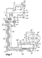
- FIG. 4 there is illustrated another embodiment of this invention in which a system 155 produces mechanical power instead of distillation.
- a system 155 produces mechanical power instead of distillation.
- Components that are common with those of Figures 2 and 3 have been given the same reference characters.
- the low temperature separator 101 and the low temperature condenser 113 with respective heat exchangers 104 and 114 function similarly to like components of Figure 2 to provide means to separate solute from absorbent solution and thus establish a temperature and/or pressure potential difference between the condensed solute in the condenser 113 and the remaining solution in the separator 101.
- vapor conduit 110 which provides a vapor channel from the separator 101 to the low temperature condenser 113
- booster 154 similar to that of the distillation system 150 of Figure 3 for mechanically aidi: g the separation of the two working fluids when a natural temperature difference between the heat exchangers 104 and 114 is not adequate to promote the transfer of refrigerant vapor for its separation.
- Heat exchanger 104 which can circulate cold water, provides means to thus maintain the low temperature separator 101 at a predetermined low temperature.
- the heat exchanger 120 includes the same conduit passages 102,109,115, and 122 as those of systems 20 and 150. It also functions similarly to raise the temperature of separated solute and remaining concentrated solution, to thus amplify the temperature and/or vapor pressure potential difference between the condensed solute and the remaining concentrated solution.
- the working fluids used in system 155 of Figure 4 are similar to fluids of systems 20 and 150.
- the solute boiler 156 with a heat transfer surface 157 and with a liquid control means 158 is provided for receiving the heated solute refrigerant by means of the conduit 115. Also included is a residue purging means 159, an alternate boiler heat exchanger 160, and a hot vapor solute conduit 161.
- the alternate heat exchanger 160 which is in thermal association with the boiler 156 provides alternate means for maintaining and stabilizing a high temperature absorber 162 at a higher temperature than the separator 101.
- the boiler 156 and heat transfer surface 157 are in thermal association with the absorber 162.
- the vapor conduit 161 directs solvent vapor to a power converter means 163 (such as a turbine or a positive displacement expander), which power converter means 163 exhausts solvent vapor through a conduit 164 into the absorber 162.
- the purpose of the power converter means 163 is to convert amplified vapor pressure potential energy into mechanical work.
- the power converter 163 is the means for recovering the amplified vapor pressure potential difference generated between the absorber 162 and the boiler 156.
- a heat exchanger 167 which is in the thermal association with the absorber 162 is preferred to maintain and stabilize the temperature of the absorber 162 at a higher temperature than that of the separator 101.
- the counter-flow heat exchanger 120 provides means for cooling diluted solution as it passes from the absorber 162 back to the separator 101.
- the operation of the temperature pressure potential amplifier as the power system 155 of Figure 4 is as follows: Dilute absorbent solution enters the low temperature separator 101 through the supply conduit 102, and concentrated absorbent solution leaves through the conduit 109. Proper liquid level is maintained in the low temperature separator 101 by the liquid control means 103. Heat is supplied to the separator 101 by cold water passing through the heat exchanger 104, which heat evaporates solute from the solution in the separator 101, and the resulting vapor, carrying heat of vaporization with it, passes through the conduit 110 and the blower 154 into the low temperature condenser 113 which is cooled by cold water flowing through the heat exchanger 114.
- the power driven blower 154 must be used as a booster if the water flowing through the exchanger 114 is not sufficiently colder than the water flowing through the heat exchanger 104.
- the separation of pure solute from absorbent solution provides storage of temperature and/or pressure potential energy.
- the concentrated absorbent solution remaining to be discharged from the separator 101 is pumped out through the conduit 109 by the pump means 117 which includes gravity aid, while condensed solute is pumped from the condenser 113 by the pump means 116 which includes gravity aid, and both liquids are heated to a higher temperature by passing through the counter-flow exchanger 120 where heat is absorbed from hot diluted absorbent solution counter flowing through the conduit 102 in the heat exchanger 120.
- any required make up heat is supplied by naturally heated or stored hot water also counter flowing in the external heat supply conduit 122.
- solute liquid is heated in the conduit 115, and concentrated absorbent solution is heated in the conduit 109, the pressure potential energy is amplified due to the rapidly increasing vapor pressure difference between these two fluids.
- Solute liquid is pumped into the boiler 156, while concentrated solution is delivered through a distributor 168 to form a solution film over the boiler heat transfer surface 157.
- the purging means 159 is provided to eliminate any contaminating solvent which might accumulate in the boiler 156.
- the make up heat delivered to the solute in the boiler 156 from an external source through the heat exchanger 160 helps evaporate solute in the boiler 156 and also maintains and stabilizes the high temperature absorber 162 at a higher temperature than the separator 101.
- Vapor solute carrying heat of vaporization is directed into the power converter 163 and is exhausted through the conduit 164 into the absorber 162 where it is absorbed into solution and the heat of absorption is transferred out of the absorber 162 by the heat transfer surface 157, thus reducing the back pressure within the absorber 162 and also providing heat for evaporation of the solute within the boiler 156.
- the solute vapor produced in the boiler 156 powers the power converter 163.
- the mechanical power delivered by the power converter 163 is the useful vapor pressure potential output of the system 155.
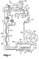
- the temperature pressure potential amplifier system 170 of Figure 5 is an embodiment of this invention for generating power and/or for heat pumpng by means of vapor flow between and from components at temperatures that are below the temperature of the absorber 162, with the assistance of the power driven blower 154 and a compressor.
- the components of the system 170 include a similar low temperature separator 101 and low temperature condenser 113 with corresponding vapor conduit 110 and vapor blower 154 as the system 155 of Figure 4 to provide means to separate solute refrigerant from absorbent solution, to thus establish a temperature and/or vapor pressure potential difference between the condensed solute and the remaining concentrated solution in the separator 101.
- heat pump components including an ambient temperature boiler means 171, a heat exchanger 172 thermally associated with the low temperature separator 101 and the boiler means 171, a liquid refrigerant supply conduit 173, a liquid level control means 174, and a power driven vapor compressor 175 receiving vaporized solute from the ambient temperature boiler 171 and delivering the vapor to the absorber 162.
- the heat exchanger 172 functions to maintain the low temperature separator 101 and the ambient temperature boiler 171 at predetermined temperatures.
- the heat pump assembly including the power driven refrigerant compressor 175 is thermally associated with the ambient temperature boiler 171 and with the absorber 162, to thus transfer heat to the absorber 162 to maintain the temperature of the absorber at a usefully higher temperature than the temperature of the separator 101.
- a counter-flow heat exchanger 176 having but three conduit passages 102, 109, and 115 replaces the heat exchanger 120 of Figure 2, 3 and 4.
- the heat exchanger 176 raises the temperature of the remaining concentrated solution within the separator 101 and a portion of the condensed solute, thus amplifying the temperature and/or vapor pressure potential difference between such condensed solute and such remaining portion of the concentrated solution.
- the counter-flow heat exchanger 176 also provides means for cooling diluted solution returning from the absorber 162 to the separator 101.
- the operation of the system 170 of Figure 5 for generating power is the same as the operation of the system 155 of Figure 4 except that in the system 170 the high temperature make up heat is supplied to the absorber 162 by a heat pump assembly and the cycle of which also exhibits temperature and pressure potential amplification.
- the system 170 of Figure 5 operates as follows when generating power: Some condensed solute is delivered from the low temperature condenser 113 to the ambient temperature boiler 171 through the liquid refrigerant conduit 173 to maintain a suitable liquid level in the boiler 171 as regulated by the liquid level control means 174.
- External ambient heat is supplied to the ambient temperature boiler 171 by means of the heat exchanger 172 at a temperature that may be so much lower than the temperature of the absorber 162 that the power driven vapor compressor 175 must add pressure to that of the vapor leaving the ambient temperature boiler 171 to deliver such vapor and its contained latent heat to the absorber 162.
- the vapor pressure of absorbent solution is less than that of pure solute at the same temperature. The pressure reduction within the absorber 162 increases the efficiency of the compressor 175 and reduces the power which must be expended by the compressor 175 to provide the required compression ratio for heat pumping.
- the heat necessary for power conversion which must be supplied by the vapor delivered by means of the heat pump compressor 175 is but a small fraction of the total heat delivered to the solute boiler 156. Heat is also recycled to the solute boiler 156 from the absorber 162 through the heat exchange surface 157.
- the temperature in the condenser 113 must be maintained sufficiently low that the vapor pressure in the condenser 113 is lower than the vapor pressure of concentrated solution in the separator 101.
- the temperature in the separator 101 is maintained at 10.0°C (50 Deg. F) corresponding to available ground water circulating through the heat exchanger 172, and the temperature in the condenser 113 is at -4.4°C (24 Deg.
- heat pumping may be self sustained with little necessity for supplying external power to either the vapor compressor 175 or to the booster blower 154.
- Temperature pressure amplification is demonstrated here, since the difference in temperature represented by 27.8°C (82 Deg. F) minus 10.0°C (50 Deg. F) of the heat pump cycle to the absorber 162 is greater than the temperature difference 10.0°C (50 Deg. F) minus -4.4°C (24 Deg. F) of the low temperature separation cycle between the separator 101 and the condenser 113.
- power must be added to the vapor compressor 175. This may be done by driving the compressor 175 with power delivered from the power converter 163.
- Both the power converter 163 and the vapor compressor 175 may be replaced, if desired, by a single turbocompressor (not shown).
- the boiler 156 and power converter 163 with the associated components 115, 157, 158, 159, and 161 can be omitted.
- all the refrigerant solute liquid leaving the low temperature condenser 113 is pumped into the ambient temperature boiler 171, and the vaporized solute leaving the boiler 171 is supplied to the absorber 162 by the power driven vapor compressor 175, and the heat of absorption released at the absorber 162 is delivered as useful heat by the heat exchanger 167 to space to be heated.
- the counter-flow heat exchanger 176 is still the means for raising the temperature of the concentrated absorbent solution, thus amplifying the temperature difference between the condensed solute and the concentrated solution.
- the means for recovering the amplified temperature and/or vapor pressure potential difference (specifically the amplified temperature difference) generated between the ambient temperature boiler 171 and the absorber 162 includes the heat exchanger 167.
- the vapor compressor 175 aids in providing the means for maintaining the absorber 162 at a higher temperature than that of the separator 101 or ambient temperature boiler 171.
- the heat exchanger 172 which may circulate ambient temperature water is the heat supply means for maintaining the sabilizing the separator 101 and the ambient temperature boiler 171 at predetermined temperatures.
- the low temperature heat exchanger 114 serves as a heat sink which dissipates heat from the condenser 113 to still colder air, thus causing condensation of separated solute vapor in the condenser 113.
- the booster blower 154 which is externally powered, provides any additional vapor pressure needed to deliver solute vapor to the condenser 113, if the condenser 113 is not sufficiently colder than the separator 101.
- fluids such as R-152a and 55.5 wt.% R-152a in n-propanol solution as of Table 1 might be more suitable working fluids to use.
- the operating temperature in the absorber 162 should be as high as 48.9°C (120 Deg. F) or 60.0°C (140 Deg. F).
- the heat exchanger 172 provides means for maintaining the low temperature separator 101 and the boiler 171 at predetermined temperatures. If the temperature of the separator 101 is 4.4°C (40 Deg. F) for example, the condenser 113 needs to be at 1.7°C (35 Dg.
- This temperature difference of 2.8°C (5 Deg. F) may be supplied by ocean water at different depths or from other common natural temperature differences. If this natural difference of temperature is not available, the power driven blower 154 can induce vapor to flow from the low temperature separator 101 to the condenser 113 and thus induce heat flow to recycle, through heat exchangers 114 and 172 if they are in common communication with a low temperature heat source, back to the low temperature separator 101. In this case, a small amount of power is required to drive the booster blower 154. (See Table 1).
- the peat pump circuit including the compressor 175 provides means for maintaining the high temperature absorber 162 at a temperature higher than that of the separator 101 and the ambient temperature boiler 171. Heat that is liberated by vapor absorbed in the absorber 162 at, for example, 48.9°C (120 Deg. F), is transmitted back through the boiler transfer surface 157 into the boiler 156 in nearly sufficient quantity to produce all the solute vapor at the amplified pressure to drive the power converter 163. The potential energy in this process is some 6.98x10 3 Joule/kg (3.0 BTU per pound). (See Table 1).
- the small hydraulic load of the pumps 116 and 117 can be reduced by mounting the counter-flow heat exchanger 176 in a vertical position as illustrated in the figures so that gravity provides part of the driving pressure.
- System 180 of Figure 6 is still another embodiment of the heat transfer teachings of this invention in which refrigeration and/or air conditioning or power production are desired when a cooling tower may be the only practical heat sink. Suitable working fluids are illustrated by data of Table 1.
- the components of the low temperature region of system 180 are similar to those of system 150 of Figure 3 and carry the same reference characters. Also like components of Figures 5 and 6 have been given the same reference characters.
- the low temperature separator 151 is supplied with dilute absorbent solution through the supply duct 102 and associated flow regulator 118.
- the low temperature separator 151 is in thermal communication with an external space that is to be refrigerated or air conditioned by means of the heat exchanger 104.
- the power driven blower 154 in the conduit 110 leaving the low temperature separator 151 functions to provide the flow of solute vapor from the low temperature separator 151 into the low temperture condenser 153 by which heat is recycled to the low temperature separator 151 through the heat transfer surface 152.
- absorbent solution is concentrated in the separator 151 to thus establish a temperature and/or vapor pressure potential difference between the condensed solute and the remaining concentrated solution in the separator 151.
- the concentrated solution conduit 109 carries concentrated solution from the separator 151 through the counter-flow heat exchanger 176 to an absorber distributor 181 within an absorber 182, while the liquid solute conduit 115 carries liquid refrigerant solute through the counter-flow heat exchanger 176 to a solute boiler 183 to raise the temperature of the respective concentrated solution and the liquid solute to thus provide means to amplify the temperature and/or vapor pressure potential difference between the solution in the absorber 182 and the solution in the boiler 183.
- a heat exchanger 184 and air fin heat exchanger 185 are in heat transfer relationship with the boiler 183 to receive heat from a higher temperature source than exchanger 104, thus functioning to recover the amplified temperature and/or vapor pressure potential difference generated between the absorber 182 and the boiler 183. Diluted solution flows in the opposite direction through the conduit 102 in the heat exchanger 176, thus providing means for cooling the diluted solution flowing back from the absorber 182 to the low temperature separator 151.
- the power converter means 163 can function to deliver power as in the system 155, but also can be driven by an external power source when extra pressure is required to drive solute vapor through the conduit 164 from the solute boiler 183 and thence into the absorber 182, where heat of absorption is rejected through the heat exchanger 187.
- the temperature of the absorber 182 is maintained at a higher temperature than that of the separator 151 by a heat exchanger 187 which is in thermal association with the absorber 182 and which dissipates heat to an environment such as a cooling tower at a temperaure a little lower than that of the absorber 182.
- the operation of the system 180 of Figure 6 for refrigeration and air conditioning is as follows:
- the vapor compressor 175 is driven to reduce the vapor pressure and thus the temperature in the low temperature separator 151, for example to predetermine -6.7°C (20 Deg. F), which would refrigerate a desired space by means of the heat exchanger 104.
- Additional refrigerant solute vapor is withdrawn from the low temperature separator 151 through the vapor conduit 110 with the assistance of the power driven blower 154, thus concentrating the remaining absorbent solution in the separator 151 and generating a temperature and/or vapor pressure potential difference between refrigerant solute and the remaining solution.
- This said portion of the refrigerant solute vapor is delivered to the condenser 153 at a pressure only sufficiently greater than the pressure in the low temperature separator 151 to be condensed and to maintain the temperature in the condenser 153 slightly above the temperature in the low temperature separator 151 to thus allow heat of vaporization to recycle from the condenser 153 back to the low temperature separator 151. (See Table 1).
- the blower 154 requires but a small amount of power because the vapor pressure difference is small.
- the concentrated solution from the separator 151 is then delivered by the pump means 117 through the counter-flow heat exchanger 176 where it is heated, while the liquid refrigerant solute is also delivered from the condenser 153 by the pump means 116 (assisted by gravity) through the counter-flow heat exchanger 176 where it is heated and is then delivered to the solute boiler 183.
- the temperature and/or vapor pressure potential difference is thus amplified in the heat exchanger 176.
- the temperature of the absorber 182 receiving the concentrated and heated absorbent solution is stabilized at the higher temperature by an external heat sink such as a cooling tower through thermal communication with the heat exchanger 187. Absorption of refrigerant vapor takes place in the absorber 182 at this stabilized temperature, for example, 26.7°C (80 Deg. F), if the vapor pressure is sufficiently low in the absorber 182 that vapor can be received from the solute boiler 183 which may be several degrees cooler, for example, 21.1°C (70 Deg. F). (See Table 1). If a lower temperature such as 10.0°C (50 Deg.
- solute boiler 183 F
- power is supplied to drive the power converter means 163 to maintain a flow of solute vapor from the solute boiler 183 which is in thermal communication with the external space to be cooled or air conditioned by means of the heat exchanger 184 or the air fin exchanger 185.
- all the heat for evaporation in the boiler 183 is supplied from the ambient space to be cooled.
- absorbent solution becomes diluted in the absorber 182 it is returned through the conduit 102 and the flow regulator 118 and is cooled as it passes through the heat exchanger 176 to be returned to the low temperature separator 151.
- the operation of the heat pump compressor 175 is controlled by a thermostat to maintain the desired refrigerating temperature in the low temperature separator 151.
- the temperature pressure potential amplifier system 180 of Figure 6 can function as a thermally powered air conditioner or as a power generator if the heat supplied to the solute boiler 183 by the heat exchanger 184 or 185 is at a sufficiently high temperature, for example at a temperature above that of the absorber 182, that the vapor pressure within the boiler 183 is greater than the back vapor pressure within the absorber 182.
- the power converter 163 as illustrated can thus function either as a power generator or as a vapor blower, depending on the relative temperature of the environment to which heat can be rejected by the heat exchanger 187 and the temperature of the boiler 183.
- the operation of the system 180 of Figure 6 for thermally powered air conditioning or for power production is as follows:
- the vapor compressor 175 is driven to reduce the vapor pressure and thus the temperature in the low temperature separator 151, for example, to a predetermined 10.0°C (50 Deg. F), sufficiently low temperature to cool a space to be air conditioned by means of the heat exchanger 104.
- Additional refrigerant solute vapor is withdrawn from the low temperature separator 151 through the vapor conduit 110 by means of the power driven blower 154, thus concentrating the solution in the separator 151 so that the remaining concentrated solution contains a higher percent of high boiling point solvent.
- the said additional portion of solute vapor is delivered to the condenser 153 and is condensed to a liquid, thus establishing a temperature and/or vapor pressure potential difference between the solute and remaining concentrated solution.
- the blower 154 requires but a small amount of power.
- Both the solute and the remaining concentrated solution are heated by passing through the heat exchanger 176, thus amplifying the temperature and/or vapor pressure potential difference between the solute and solution as they are delivered to the respective boiler 183 and absorber 182.
- the temperature of the absorber 182 is stabilized at a temperature (for example 26.7°C (80 Deg. F)) which is above the temperature of the separator 151 by thermal association of a heat sink such as a cooling tower by means of the heat exchanger 187.
- the boiler 183 may be supplied with higher temperature heat (for example 43.3°C (110 Deg. F)) from natural sources by means of the heat exchangers 184 or 185, thus maintaining a higher refrigerant vapor pressure in the boiler 183 than in the absorber 182.
- the power converter 163 delivers power, at least a portion of which can be used to drive the blower 154 and the heat pump compressor 175.
- the temperature of the boiler 183 may be a little less than that of the absorber 182 so that it may receive heat directly from the absorber 182 by changing the heat exchanger 185 to function like the heat transfer surface 167 of the system 155 of Figure 4 to provide the means to remove heat from the absorber 182.
- heat exchange means including two or three heat exchangers (not shown) can be substituted for the counter-flow heat exchanger shown in each of the embodiments, one heat exchanger for instance could be used for raising the temperature of the concentrated solution, another for raising the temperature of the condensed solute and a third heat exchanger for cooling the diluted solution returning from the absorber to the separator means.
- the cooling of the diluted solution may be accomplished by one of the first two heat exchangers (not shown).
- Power can be produced efficiently by means of heat transfer from an ambient temperature heat source to a lower temperature heat sink.
- the teachings of this invention can provide heat pumps which would require less power input, especially during cold weather.
- the teachings of this invention can provide air conditioning with more efficient use of supplied power.
Landscapes
- Engineering & Computer Science (AREA)
- Mechanical Engineering (AREA)
- General Engineering & Computer Science (AREA)
- Chemical & Material Sciences (AREA)
- Combustion & Propulsion (AREA)
- Physics & Mathematics (AREA)
- Thermal Sciences (AREA)
- Sorption Type Refrigeration Machines (AREA)
- Gas Separation By Absorption (AREA)
- Vaporization, Distillation, Condensation, Sublimation, And Cold Traps (AREA)
Priority Applications (1)
| Application Number | Priority Date | Filing Date | Title |
|---|---|---|---|
| AT84109558T ATE47627T1 (de) | 1983-08-15 | 1984-08-10 | Als temperaturdruckpotentialverstaerker arbeitendes waermeuebertragungssystem der absorptionsart. |
Applications Claiming Priority (2)
| Application Number | Priority Date | Filing Date | Title |
|---|---|---|---|
| US06/523,185 US4506524A (en) | 1983-08-15 | 1983-08-15 | Absorption type heat transfer system functioning as a temperature pressure potential amplifier |
| US523185 | 1983-08-15 |
Publications (3)
| Publication Number | Publication Date |
|---|---|
| EP0137211A2 EP0137211A2 (en) | 1985-04-17 |
| EP0137211A3 EP0137211A3 (en) | 1986-01-08 |
| EP0137211B1 true EP0137211B1 (en) | 1989-10-25 |
Family
ID=24083997
Family Applications (1)
| Application Number | Title | Priority Date | Filing Date |
|---|---|---|---|
| EP84109558A Expired EP0137211B1 (en) | 1983-08-15 | 1984-08-10 | Absorption type heat transfer system functioning as a temperature pressure potential amplifier |
Country Status (6)
| Country | Link |
|---|---|
| US (1) | US4506524A (enExample) |
| EP (1) | EP0137211B1 (enExample) |
| JP (1) | JPS60144573A (enExample) |
| AT (1) | ATE47627T1 (enExample) |
| CA (1) | CA1220353A (enExample) |
| DE (1) | DE3480296D1 (enExample) |
Families Citing this family (4)
| Publication number | Priority date | Publication date | Assignee | Title |
|---|---|---|---|---|
| FR2584801B1 (fr) * | 1985-07-10 | 1990-06-15 | Electricite De France | Dispositif et installation de pompage de chaleur |
| US4915792A (en) * | 1987-02-11 | 1990-04-10 | Sten Zeilon | Process for separating a volatile component from a mixture |
| US8418466B1 (en) | 2009-12-23 | 2013-04-16 | David Hardgrave | Thermodynamic amplifier cycle system and method |
| US8656720B1 (en) | 2010-05-12 | 2014-02-25 | William David Hardgrave | Extended range organic Rankine cycle |
Family Cites Families (12)
| Publication number | Priority date | Publication date | Assignee | Title |
|---|---|---|---|---|
| DE278076C (enExample) * | 1911-08-11 | |||
| GB422150A (en) * | 1932-12-21 | 1935-01-07 | Siemens Ag | Improvements relating to heat converters comprising absorption apparatus |
| DE1020997B (de) * | 1953-11-24 | 1957-12-19 | Hagfors Hilding Jonas Einar Johansson und Per Johan George Norbäck (Schweden) | Verfahren zur Wärmeübertragung in Richtung auf höhere Temperatur |
| US3490739A (en) * | 1965-09-16 | 1970-01-20 | Walter R Buckman | Azeotropic composition containing hexafluoroacetone,hydrogen fluoride,and trichlorotrifluoroethane |
| FR1546326A (fr) * | 1966-12-02 | 1968-11-15 | Générateur d'énergie perfectionné, particulièrement pour créer une énergie enutilisant un réfrigérant | |
| FR2441135A1 (fr) * | 1978-11-10 | 1980-06-06 | Armines | Transformateur a absorption |
| FR2483009A1 (fr) * | 1980-05-23 | 1981-11-27 | Inst Francais Du Petrole | Procede de production d'energie mecanique a partir de chaleur utilisant un melange de fluides comme agent de travail |
| GB2076304B (en) * | 1980-05-26 | 1984-02-22 | Univ Sydney | Heat exchange (evaporator) device |
| US4333515A (en) * | 1980-08-13 | 1982-06-08 | Battelle Development Corp. | Process and system for boosting the temperature of sensible waste heat sources |
| US4402795A (en) * | 1980-09-18 | 1983-09-06 | Erickson Donald C | Reverse absorption heat pump augmented distillation process |
| DE3113063A1 (de) * | 1981-04-01 | 1982-10-14 | Dürr Innovation GmbH, 7000 Stuttgart | Vorrichtung zur erhoehung der temperatur eines waermetraegers auf der grundlage von absorption und austreibung, verdampfung und verfluessigung eines kaeltemittels |
| DE3140013C2 (de) * | 1981-10-08 | 1986-06-19 | Fried. Krupp Gmbh, 4300 Essen | Verfahren und Vorrichtung zur Ausnutzung eines Abdampfes |
-
1983
- 1983-08-15 US US06/523,185 patent/US4506524A/en not_active Expired - Fee Related
-
1984
- 1984-08-10 AT AT84109558T patent/ATE47627T1/de not_active IP Right Cessation
- 1984-08-10 EP EP84109558A patent/EP0137211B1/en not_active Expired
- 1984-08-10 DE DE8484109558T patent/DE3480296D1/de not_active Expired
- 1984-08-14 CA CA000460936A patent/CA1220353A/en not_active Expired
- 1984-08-14 JP JP59169877A patent/JPS60144573A/ja active Granted
Also Published As
| Publication number | Publication date |
|---|---|
| ATE47627T1 (de) | 1989-11-15 |
| EP0137211A2 (en) | 1985-04-17 |
| EP0137211A3 (en) | 1986-01-08 |
| US4506524A (en) | 1985-03-26 |
| JPH0554024B2 (enExample) | 1993-08-11 |
| JPS60144573A (ja) | 1985-07-30 |
| CA1220353A (en) | 1987-04-14 |
| DE3480296D1 (en) | 1989-11-30 |
Similar Documents
| Publication | Publication Date | Title |
|---|---|---|
| US4205529A (en) | LiCl Dehumidifier LiBr absorption chiller hybrid air conditioning system with energy recovery | |
| US5600967A (en) | Refrigerant enhancer-absorbent concentrator and turbo-charged absorption chiller | |
| EP0122017A2 (en) | Low temperature engine system | |
| KR102263742B1 (ko) | 열역학 사이클 장치 및 방법 | |
| CN103003530A (zh) | 热电能存储系统 | |
| JP2512095B2 (ja) | 冷熱発生方法 | |
| US3641784A (en) | Absorption refrigeration system with multiple absorption | |
| US2721728A (en) | Heat concentrator | |
| US20120017621A1 (en) | Cooling method and apparatus | |
| US5272878A (en) | Azeotrope assisted power system | |
| EP0527945A1 (en) | Branched gax absorption vapor compressor | |
| US4324983A (en) | Binary vapor cycle method of electrical power generation | |
| US11473817B2 (en) | Method to change fluid temperature using a thermally driven control unit | |
| EP0137211B1 (en) | Absorption type heat transfer system functioning as a temperature pressure potential amplifier | |
| JP2023073600A (ja) | 排熱利用システム | |
| US3990264A (en) | Refrigeration heat recovery system | |
| JPH02181002A (ja) | 複流体タービンプラント | |
| US5782097A (en) | Generator-absorber-heat exchange heat transfer apparatus and method and use thereof in a heat pump | |
| EP0042434B1 (en) | Method of amplifying heat | |
| US4283918A (en) | Liquid phase separation in absorption refrigeration | |
| US4240267A (en) | System for vaporizing carbon dioxide utilizing the heat by-product of the refrigeration system as a heat source | |
| JPH02188605A (ja) | 複流体タービンプラント | |
| JPH05272837A (ja) | 圧縮・吸収複合式ヒートポンプ | |
| Saravanan et al. | Influence of thermodynamic and thermophysical properties of water-based working fluids for bubble pump operated vapour absorption refrigerator | |
| JPS5928725B2 (ja) | 発電プラント |
Legal Events
| Date | Code | Title | Description |
|---|---|---|---|
| PUAI | Public reference made under article 153(3) epc to a published international application that has entered the european phase |
Free format text: ORIGINAL CODE: 0009012 |
|
| AK | Designated contracting states |
Designated state(s): AT BE CH DE FR GB IT LI LU NL SE |
|
| PUAL | Search report despatched |
Free format text: ORIGINAL CODE: 0009013 |
|
| AK | Designated contracting states |
Designated state(s): AT BE CH DE FR GB IT LI LU NL SE |
|
| 17P | Request for examination filed |
Effective date: 19860626 |
|
| 17Q | First examination report despatched |
Effective date: 19861125 |
|
| D17Q | First examination report despatched (deleted) | ||
| GRAA | (expected) grant |
Free format text: ORIGINAL CODE: 0009210 |
|
| AK | Designated contracting states |
Kind code of ref document: B1 Designated state(s): AT BE CH DE FR GB IT LI LU NL SE |
|
| PG25 | Lapsed in a contracting state [announced via postgrant information from national office to epo] |
Ref country code: SE Effective date: 19891025 Ref country code: NL Effective date: 19891025 Ref country code: LI Effective date: 19891025 Ref country code: IT Free format text: LAPSE BECAUSE OF FAILURE TO SUBMIT A TRANSLATION OF THE DESCRIPTION OR TO PAY THE FEE WITHIN THE PRESCRIBED TIME-LIMIT;WARNING: LAPSES OF ITALIAN PATENTS WITH EFFECTIVE DATE BEFORE 2007 MAY HAVE OCCURRED AT ANY TIME BEFORE 2007. THE CORRECT EFFECTIVE DATE MAY BE DIFFERENT FROM THE ONE RECORDED. Effective date: 19891025 Ref country code: FR Free format text: THE PATENT HAS BEEN ANNULLED BY A DECISION OF A NATIONAL AUTHORITY Effective date: 19891025 Ref country code: CH Effective date: 19891025 Ref country code: BE Effective date: 19891025 Ref country code: AT Effective date: 19891025 |
|
| REF | Corresponds to: |
Ref document number: 47627 Country of ref document: AT Date of ref document: 19891115 Kind code of ref document: T |
|
| REF | Corresponds to: |
Ref document number: 3480296 Country of ref document: DE Date of ref document: 19891130 |
|
| REG | Reference to a national code |
Ref country code: CH Ref legal event code: PL |
|
| EN | Fr: translation not filed | ||
| NLV1 | Nl: lapsed or annulled due to failure to fulfill the requirements of art. 29p and 29m of the patents act | ||
| PLBE | No opposition filed within time limit |
Free format text: ORIGINAL CODE: 0009261 |
|
| STAA | Information on the status of an ep patent application or granted ep patent |
Free format text: STATUS: NO OPPOSITION FILED WITHIN TIME LIMIT |
|
| PG25 | Lapsed in a contracting state [announced via postgrant information from national office to epo] |
Ref country code: LU Free format text: LAPSE BECAUSE OF NON-PAYMENT OF DUE FEES Effective date: 19900831 |
|
| 26N | No opposition filed | ||
| PGFP | Annual fee paid to national office [announced via postgrant information from national office to epo] |
Ref country code: DE Payment date: 19930723 Year of fee payment: 10 |
|
| PGFP | Annual fee paid to national office [announced via postgrant information from national office to epo] |
Ref country code: GB Payment date: 19930726 Year of fee payment: 10 |
|
| PG25 | Lapsed in a contracting state [announced via postgrant information from national office to epo] |
Ref country code: GB Effective date: 19940810 |
|
| GBPC | Gb: european patent ceased through non-payment of renewal fee |
Effective date: 19940810 |
|
| PG25 | Lapsed in a contracting state [announced via postgrant information from national office to epo] |
Ref country code: DE Effective date: 19950503 |