EP0136766B1 - Apparatus for holding a jersey-sheath in a device for covering a flat article with such a sheath - Google Patents
Apparatus for holding a jersey-sheath in a device for covering a flat article with such a sheath Download PDFInfo
- Publication number
- EP0136766B1 EP0136766B1 EP84201513A EP84201513A EP0136766B1 EP 0136766 B1 EP0136766 B1 EP 0136766B1 EP 84201513 A EP84201513 A EP 84201513A EP 84201513 A EP84201513 A EP 84201513A EP 0136766 B1 EP0136766 B1 EP 0136766B1
- Authority
- EP
- European Patent Office
- Prior art keywords
- jersey
- sheath
- arms
- arm
- covering
- Prior art date
- Legal status (The legal status is an assumption and is not a legal conclusion. Google has not performed a legal analysis and makes no representation as to the accuracy of the status listed.)
- Expired
Links
Images

Classifications
-
- B—PERFORMING OPERATIONS; TRANSPORTING
- B68—SADDLERY; UPHOLSTERY
- B68G—METHODS, EQUIPMENT, OR MACHINES FOR USE IN UPHOLSTERING; UPHOLSTERY NOT OTHERWISE PROVIDED FOR
- B68G7/00—Making upholstery
- B68G7/05—Covering or enveloping cores of pads
- B68G7/051—Mattress-filling devices, i.e. sliding a tick or preformed cover over a cushion or sliding a cushion into a tick or preformed cover, e.g. by means of a press or of a depression table
-
- B—PERFORMING OPERATIONS; TRANSPORTING
- B65—CONVEYING; PACKING; STORING; HANDLING THIN OR FILAMENTARY MATERIAL
- B65B—MACHINES, APPARATUS OR DEVICES FOR, OR METHODS OF, PACKAGING ARTICLES OR MATERIALS; UNPACKING
- B65B9/00—Enclosing successive articles, or quantities of material, e.g. liquids or semiliquids, in flat, folded, or tubular webs of flexible sheet material; Subdividing filled flexible tubes to form packages
- B65B9/10—Enclosing successive articles, or quantities of material, in preformed tubular webs, or in webs formed into tubes around filling nozzles, e.g. extruded tubular webs
- B65B9/15—Enclosing successive articles, or quantities of material, in preformed tubular webs, or in webs formed into tubes around filling nozzles, e.g. extruded tubular webs the preformed tubular webs being stored on filling nozzles
- B65B9/18—Devices for storing tubular webs
Definitions
- the invention relates to a device for holding a bundle of stockings on tricot stockings.
- upholstery bodies are used for seating.
- the furniture industry receives the upholstery bodies from the foam rubber manufacturer with a covering made of tricot material so that the upholstery bodies can be handled and their wear is prevented due to friction between the upholstery body and a later applied fabric covering, as occurs during practical use.
- the device for holding the bundle of supplies on the tricot stocking is a relatively large, essentially cuboid tubular body.
- Such tubular bodies are used for the transportation of the jersey material from the manufacturer to the customer and as part of the machine.
- the handling of these tubular bodies is disadvantageous and difficult due to their shape and dimensions. Transport and storage are expensive.
- the empty tube body is returned to the manufacturer of the jersey material, which incurs additional transportation costs.
- an annular bead is attached to the tubular body attached to the stand in the pull-off direction, which makes it difficult to pull off the jersey stocking in the pull-off direction.
- the object of the invention is to avoid these disadvantages of the known device and to further develop the device of the type mentioned at the outset in such a way that storage, transport and insertion of a bundle of stockings on jersey stockings are simplified.
- the tubular body is completely eliminated, and a removable, annular bead is also no longer required.
- the jersey supplier no longer has to rub the jersey stocking onto a tubular body, storage and transportation of the jersey bundle are simplified, the insertion of a jersey bundle into the machine is significantly simplified, and returning empty tube bodies is no longer necessary.
- a pneumatic cover press for upholstery body is known, with which a precisely fitting, sewn in the form of a cover can be drawn onto the upholstery body. So a practically endless, elastic jersey tube is not used.
- the press has two half-shells, onto which the cover is first placed and which are moved past the upholstery body when they are covered. They can be moved freely across this direction of movement so that wedge-shaped upholstery bodies can also be covered. However, if cuboidal upholstered bodies are covered, the lateral displacement is unnecessary.
- At least one of the two brackets is made of tubular material.
- a base plate is hinged to the stand, which can be folded between the two arms and on which the cushion body rests when it is pushed through the device.
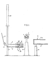
- the machine shown in Figures 1 to 5 has a gate-shaped stand 1, on which a first boom 2 and a bracket 10 are rigidly attached.
- the boom 2 has a bow shape and has a downward bend 6 at its free end.
- a second boom 3 is slidably arranged, it has an upward bend 50 at its free end, can be moved by means of a power cylinder 30 and also has a bow shape.
- the two arms 2 and 3 fit into each other in such a way that the arm 3 can be moved by the arm 2.
- a base plate is articulated on the console 10 and can be folded into a horizontal position (see FIG. 2).
- a supply bundle 4 of jersey stocking can be in the direction of the arrow 14 are pushed onto the boom 2, 3.
- This supply bundle 4 has a length of a few hundred meters and is folded.
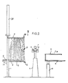
- FIG. 2 shows the next position of the device after pushing on the supply bundle 4.
- the boom 3 has been moved upwards by the power cylinder 30, as a result of which the supply bundle 4 is stretched between the booms 2, 3.
- the base plate 5 is folded into the horizontal.
- the jersey stocking spans the bends 5, 60 of the extension arm and ends in a fixation point 7, where it is combined.
- This fixation point 7 is the result of the preceding coating process of a cushion body 14.
- the machine also has a stand 8, on which a double stapler 9 and a knife 11 are mounted. Furthermore, the machine has a stand 12 on which a rod system 13 is mounted.
- a cushion body 14 is to be covered with tricot material, it is passed between the two brackets 2, 3 and pushed over the bottom plate 5 which is in a horizontal position.
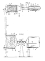
- the cushion body 14 is removed from the device with the two arms 2, 3, guided past the stapler 9 and placed in the rod system 13, see FIGS. 3 and 4.
- the cushion body 14 rests on a plate 16 and between rods 17 and 18.
- the jersey stocking has a tension in the form of a venturi 20 (FIGS. 3 and 4), for this the bends 6 and 50 play a role, at the same time a certain tension is exerted on the cushion body 14 in an opposite direction in the transport direction.
- the covered cushion body 14 cannot be moved back as a result, it is only pressed against the parts 19, 20 of the rods 17 and 18 which are bent towards one another.
- the cushion body 14 is in the rod system 13 (see FIGS. 3 and 4), an operator can grip the venturi part 20 with both hands 22, see FIG. 4, and form a strand which is inserted into the stapler 9.
- fixation points 23 and 24 arise, see FIGS. 4 u. 5.
- the operator guides the strand between the fixation points 23 and 24 along the knife 11, whereby the strand is severed and free ends 26 and 27 are formed.
- the tricot stocking snaps into the position shown in FIGS. 2 and 5, in which a section 15 is located between the free ends of the arms 2, 3 and a section 25 abuts the cushion body 14.
- the cushion body 14 can now be removed.
- recesses 28 have previously been cut into the side surfaces of the cushion body 28 by means of a rapidly rotating tube. The material is stuffed into this in the area of the fixation points 7 and 27, see FIG. 6.
- a further cushion body 14 can be inserted into the machine and covered with a tricot stocking.
Abstract
Description
Die Erfindung betrifft eine Vorrichtung zum Halten eines Vorratsbündels an Trikotstrumpf nach dem Oberbegriff des Anspruchs 1. Mit diesem Trikotmaterial werden insbesondere Polsterkörper aus Schaumgummi oder einem anderen, allseitig zusammenpressbarem, elastischem Material umhüllt. Derartige Polsterkörper werden für Sitzmöbel verwendet. Die Möbelbranche erhält die Polsterkörper vom Schaumgummifabrikanten mit einer Umhüllung aus Trikotmaterial, damit die Polsterkörper hantierbar sind und ihrer Abnutzung aufgrund von Reibung zwischen dem Polsterkörper und einem später angebrachten Stoffüberzug, wie sie während der praktischen Verwendung auftritt, vorgebeugt wird.The invention relates to a device for holding a bundle of stockings on tricot stockings. Such upholstery bodies are used for seating. The furniture industry receives the upholstery bodies from the foam rubber manufacturer with a covering made of tricot material so that the upholstery bodies can be handled and their wear is prevented due to friction between the upholstery body and a later applied fabric covering, as occurs during practical use.
Bei der aus dem Prospekt TRICOVER des Anmelders bekannten Maschine zum Beziehen eines quaderförmigen Gegenstandes mit Trikotmaterial ist die Vorrichtung zum Halten des Vorratsbündels an Trikotstrumpf ein relativ großer, im wesentlichen quaderförmiger Rohrkörper. Derartige Rohrkörper verwendet man für den Transport des Trikotmaterials vom Fabrikanten zum Abnehmer und als Teil der Maschine. Die Handhabung dieser Rohrkörper ist aufgrund ihrer Form und Abmessungen nachteilig und schwierig. Transport und Lagerung sind teuer. Die leeren Rohrkörper werden dem Fabrikanten des Trikotmaterials zurückgegeben, wodurch weitere Transportkosten entstehen. In der Maschine wird an den am Ständer befestigten Rohrkörper in Abzugsrichtung noch ein ringförmiger Wulst angebracht, der ein Abziehen des Trikotstrumpfes in Abzugsrichtung erschwert.In the machine known from the applicant's TRICOVER prospectus for covering a cuboid article with tricot material, the device for holding the bundle of supplies on the tricot stocking is a relatively large, essentially cuboid tubular body. Such tubular bodies are used for the transportation of the jersey material from the manufacturer to the customer and as part of the machine. The handling of these tubular bodies is disadvantageous and difficult due to their shape and dimensions. Transport and storage are expensive. The empty tube body is returned to the manufacturer of the jersey material, which incurs additional transportation costs. In the machine, an annular bead is attached to the tubular body attached to the stand in the pull-off direction, which makes it difficult to pull off the jersey stocking in the pull-off direction.
Aufgabe der Erfindung ist es, diese Nachteile der bekannten Vorrichtung zu vermeiden und die Vorrichtung der eingangsgenannten Art dahingehend weiterzubilden, daß Lagerung, Transport und Einsetzen eines Vorratsbündels an Trikotstrumpf vereinfacht werden.The object of the invention is to avoid these disadvantages of the known device and to further develop the device of the type mentioned at the outset in such a way that storage, transport and insertion of a bundle of stockings on jersey stockings are simplified.
Diese Aufgabe wird gelöst durch eine Vorrichtung mit den Merkmalen des Patentanspruchs 1.This object is achieved by a device with the features of
Der Rohrkörper entfällt gänzlich, ein abnehmbarer, ringförmiger Wulst ist ebenfalls nicht mehr erforderlich. Der Trikotlieferant muß den Trikotstrumpf nicht mehr auf einen Rohrkörper streifen, Lagerung und Transport des Trikotbündels sind vereinfacht, das Einsetzen eines Trikotbündels in die Maschine ist bedeutend vereinfacht, ein Rücktransport leerer Rohrkörper entfällt.The tubular body is completely eliminated, and a removable, annular bead is also no longer required. The jersey supplier no longer has to rub the jersey stocking onto a tubular body, storage and transportation of the jersey bundle are simplified, the insertion of a jersey bundle into the machine is significantly simplified, and returning empty tube bodies is no longer necessary.
Aus der DE-B-21 51 966 ist eine pneumatische Beziehpresse für Polsterkörper bekannt, mit der ein paßgenauer, in Form einer Hülle genähter Bezug auf den Polsterkörper aufgezogen werden kann. Es wird also nicht ein praktisch endloser, elastischer Trikotschlauch verwendet. Die Presse hat zwei Halbschalen, auf die der Bezug zunächst gestülpt wird und die beim Beziehen seitlich am Polsterkörper vorbeibewegt werden. Sie sind quer zu dieser Bewegungsrichtung frei verschiebbar, damit auch keilförmige Polsterkörper bezogen werden können. Werden jedoch quaderförmige Polsterkörper bezogen, so ist die seitliche Verschiebbarkeit unnötig.From DE-B-21 51 966 a pneumatic cover press for upholstery body is known, with which a precisely fitting, sewn in the form of a cover can be drawn onto the upholstery body. So a practically endless, elastic jersey tube is not used. The press has two half-shells, onto which the cover is first placed and which are moved past the upholstery body when they are covered. They can be moved freely across this direction of movement so that wedge-shaped upholstery bodies can also be covered. However, if cuboidal upholstered bodies are covered, the lateral displacement is unnecessary.
In einer bevorzugten Ausführungsform der Erfindung ist wenigstens einer der beiden Ausleger aus Rohrmaterial gefertigt. In einer weiteren Ausbildung ist eine Bodenplatte am Ständer angelenkt, die zwischen die beiden Ausleger geklappt werden kann und auf der der Polsterkörper aufliegt, wenn er durch die Vorrichtung geschoben wird.In a preferred embodiment of the invention, at least one of the two brackets is made of tubular material. In a further embodiment, a base plate is hinged to the stand, which can be folded between the two arms and on which the cushion body rests when it is pushed through the device.
Ein Ausführungsbeispiel einer Maschine zum Beziehen eines quaderförmigen Gegenstandes mit Trikotmaterial mit einer Vorrichtung zum Halten eines Vorratsbündels an Trikotstrumpf wird im folgenden unter Bezugnahme auf die Zeichnung erläutert, in dieser zeigen :
Figur 1 eine schematische Seitenansicht einer Maschine zum Beziehen eines quaderförmigen Gegenstandes mit Trikotmaterial mit einer Vorrichtung zum Halten eines Vorratsbündels an Trikotstrumpf, gezeigt ist die Position, in der die Vorrichtung mit einem Vorratsbündel an Trikotstrumpf gefüllt wird,Figur 2 eine Ansicht entsprechendFigur 1, jedoch in einer Position, bei der die Ausleger auseinander gezogen sind, diese Position ist die Ausgangslage für das Beziehen eines Polsterkörpers mit Trikotmaterial,Figur 3 eine Draufsicht auf die Maschine in Richtung des Pfeils 111 in Fig. 2, gezeigt ist eine Position, bei der ein Polsterkörper bereits durch die Vorrichtung hindurch geführt ist,- Figur 4 eine Seitenansicht entsprechend Fig. 1 für den in Fig. 3 gezeigten Zustand, wobei zusätzlich eine Bedienungsperson einen Strang gebildet hat,
Figur 5 eine Seitenansicht entsprechend Fig. 1 in einem Zustand, bei dem der Strang an zwei Stellen fixiert, zwischen den Fixationsstellen durchgeschnitten und ein Polsterkörper umhüllt ist undFigur 6 eine Seitenansicht eines mit Trikotmaterials überzogenen Polsterkörpers mit seitlichen Ausnehmungen im Polsterkörper.
- 1 shows a schematic side view of a machine for covering a cuboid article with tricot material with a device for holding a bundle of stockings on a tricot stocking, the position is shown in which the device is filled with a bundle of stockings on tricot stocking,
- FIG. 2 shows a view corresponding to FIG. 1, but in a position in which the extension arms are pulled apart, this position is the starting position for covering a cushion body with jersey material,
- 3 shows a plan view of the machine in the direction of arrow 111 in FIG. 2, a position is shown in which a cushion body is already passed through the device,
- FIG. 4 shows a side view corresponding to FIG. 1 for the state shown in FIG. 3, an operator also forming a strand,
- 5 shows a side view corresponding to FIG. 1 in a state in which the strand is fixed at two points, cut through between the fixation points and a cushion body is encased and
- FIG. 6 shows a side view of a cushion body covered with jersey material with lateral recesses in the cushion body.
Die in den Figuren 1 bis 5 gezeigte Maschine hat einen torförmigen Ständer 1, an dem ein erster Ausleger 2 und eine Konsole 10 starr befestigt sind. Der Ausleger 2 hat eine Bügelform und weist an seinem freien Ende eine Abwärtsbiegung 6 auf. Am Ständer 1 ist ein zweiter Ausleger 3 verschiebbar angeordnet, er hat an seinem freien Ende eine Aufwärtsbiegung 50, ist mittels eines Kraftzylinders 30 bewegbar und hat ebenfalls eine Bügelform.The machine shown in Figures 1 to 5 has a gate-
Die beiden Ausleger 2 und 3 passen ineinander in einer solchen Weise, daß der Ausleger 3 durch den Ausleger 2 bewegt werden kann. An der Konsole 10 ist eine Bodenplatte angelenkt, die in eine horizontale Position (siehe Figur 2) geklappt werden kann. In der in Fig. 1 wiedergegebenen Position der Ausleger 2 und 3 kann ein Vorratsbündel 4 an Trikotstrumpf in Richtung des Pfeils 14 auf die Ausleger 2, 3 aufgeschoben werden. Dieses Vorratsbündel 4 hat eine Länge von einigen hundert Metern und ist gefältet.The two
In Fig. 2 ist die nächste Position der Vorrichtung nach Aufschieben des Vorratsbündels 4 gezeigt. Der Ausleger 3 ist durch den Kraftzylinder 30 nach oben bewegt worden, dadurch ist das Vorratsbündel 4 zwischen den Auslegern 2, 3 aufgespannt. Die Bodenplatte 5 ist in die Horizontale geklappt. Der Trikotstrumpf umspannt die Biegungen 5, 60 der Ausleger und endet in einem Fixationspunkt 7, wo er zusammengefaßt ist. Dieser Fixationspunkt 7 ist das Ergebnis des vorangehenden Überzugsvorganges eines Polsterkörpers 14.2 shows the next position of the device after pushing on the supply bundle 4. The
Die Maschine hat weiterhin einen Ständer 8, an dem ein Doppel-Heftapparat 9 und ein Messer 11 montiert sind. Weiterhin hat die Maschine einen Ständer 12, auf dem ein Stabsystem 13 montiert ist.The machine also has a
Wenn ein Polsterkörper 14 mit Trikotmaterial bezogen werden soll, wird er zwischen den beiden Auslegern 2, 3 hindurchgeführt und dabei über die in waagerechter Lage befindliche Bodenplatte 5 geschoben. Der Polsterkörper 14 wird aus der Vorrichtung mit den beiden Auslegern 2, 3 herausgenommen, am Heftapparat 9 vorbeigeführt und in das Stabsystem 13 gestellt, siehe Fig. 3 und 4. Hier ruht der Polsterkörper 14 auf einer Platte 16 und zwischen Stäben 17 und 18. Der Trikotstrumpf hat sich dabei in Form eines Venturis 20 (Fig. 3 und 4) gespannt, hierfür spielen die Biegungen 6 und 50 eine Rolle, zugleich wird ein gewisser Zug auf den Polsterkörper 14 in einer in Transportrichtung entgegengesetzten Richtung ausgeübt. Der umhüllte Polsterkörper 14 kann hierdurch jedoch nicht zurückbewegt werden, er wird lediglich gegen die aufeinanderzu gebogenen Teile 19, 20 der Stäbe 17 und 18 gedrückt.If a
Wenn sich der Polsterkörper 14 im Stabsystem 13 befindet (siehe Fig. 3 u. 4) kann eine bedienende Person das Venturiteil 20 mit beiden Händen 22, siehe Fig. 4, greifen und einen Strang bilden, der in den Heftapparat 9 eingeführt wird. Beim Heftvorgang entstehen Fixationspunkte 23 und 24, siehe Fig. 4 u. 5. Gleichzeitig oder später führt die Bedienungsperson den Strang zwischen den Fixationspunkten 23 und 24 an dem Messer 11 entlang, wodurch der Strang durchtrennt wird und freie Enden 26 und 27 entstehen. Sobald er losgelassen wird, schnellt der Trikotstrumpf in die in Fig. 2 und 5 gezeigte Lage, in der sich ein Teilstück 15 zwischen den freien Enden der Ausleger 2, 3 befindet ein Teilstück 25 am Polsterkörper 14 anliegt. Der Polsterkörper 14 kann nun entnommen werden.If the
In einer bevorzugten Ausbildung sind zuvor in die Seitenflächen des Polsterkörpers 28 mittels eines schnell rotierenden Röhrchens Ausnehmungen 28 eingeschnitten worden. In diese stopft man das Material im Bereich der Fixationspunkte 7 und 27, siehe Fig. 6.In a preferred embodiment,
Nachdem nun wieder die in Fig. 2 gezeigt Ausgangslage erreicht ist, kann ein weiterer Polsterkörper 14 in die Maschine eingeführt und mit Trikotstrumpf umhüllt werden.After the starting position shown in FIG. 2 has been reached again, a
Ist das Vorratsbündel 4 an Trikotstrumpf aufgebraucht, so wird der Ausleger 3 wieder in die unterste Position bewegt, wie sie in Fig. 1 dargestellt ist. Ein neues Vorratsbündel 4 an Trikotstrumpf kann nun aufgeschoben werden.If the supply bundle 4 of jersey stocking is used up, the
Claims (4)
Priority Applications (1)
| Application Number | Priority Date | Filing Date | Title |
|---|---|---|---|
| AT84201513T ATE20041T1 (en) | 1983-10-24 | 1984-10-18 | CONTAINER FOR HOLDING A SUPPLY BUNDLE OF SHIRT STOCKING, IN A DEVICE FOR OBTAINING A TRAY-SHAPED ITEM IN SAID SHIRT. |
Applications Claiming Priority (2)
| Application Number | Priority Date | Filing Date | Title |
|---|---|---|---|
| NLAANVRAGE8303647,A NL187006C (en) | 1983-10-24 | 1983-10-24 | Apparatus for holding a stocking stocking stock. |
| NL8303647 | 1983-10-24 |
Publications (3)
| Publication Number | Publication Date |
|---|---|
| EP0136766A2 EP0136766A2 (en) | 1985-04-10 |
| EP0136766A3 EP0136766A3 (en) | 1985-06-05 |
| EP0136766B1 true EP0136766B1 (en) | 1986-05-28 |
Family
ID=19842600
Family Applications (1)
| Application Number | Title | Priority Date | Filing Date |
|---|---|---|---|
| EP84201513A Expired EP0136766B1 (en) | 1983-10-24 | 1984-10-18 | Apparatus for holding a jersey-sheath in a device for covering a flat article with such a sheath |
Country Status (4)
| Country | Link |
|---|---|
| EP (1) | EP0136766B1 (en) |
| AT (1) | ATE20041T1 (en) |
| DE (1) | DE3460178D1 (en) |
| NL (1) | NL187006C (en) |
Cited By (2)
| Publication number | Priority date | Publication date | Assignee | Title |
|---|---|---|---|---|
| DE102010003764A1 (en) | 2009-05-12 | 2011-03-17 | Chris Heynen Systems B.V. | Device for encasing of mattress with hose-type tricot material, has sliding surface and encasing station that are arranged in swivelable manner around horizontal swiveling axis that runs transverse to conveying direction |
| WO2012159885A1 (en) | 2011-05-23 | 2012-11-29 | Heynen Systems B.V. | Supply package |
Families Citing this family (2)
| Publication number | Priority date | Publication date | Assignee | Title |
|---|---|---|---|---|
| DE4302904A1 (en) * | 1993-02-02 | 1994-08-04 | Johann Berger | Process for manufacturing textile airbag from tubular material |
| US5778642A (en) * | 1996-06-28 | 1998-07-14 | Free-Flow Packaging International, Inc. | System and method for use of loose fill packing materials |
-
1983
- 1983-10-24 NL NLAANVRAGE8303647,A patent/NL187006C/en not_active IP Right Cessation
-
1984
- 1984-10-18 DE DE8484201513T patent/DE3460178D1/en not_active Expired
- 1984-10-18 AT AT84201513T patent/ATE20041T1/en not_active IP Right Cessation
- 1984-10-18 EP EP84201513A patent/EP0136766B1/en not_active Expired
Cited By (6)
| Publication number | Priority date | Publication date | Assignee | Title |
|---|---|---|---|---|
| DE102010003764A1 (en) | 2009-05-12 | 2011-03-17 | Chris Heynen Systems B.V. | Device for encasing of mattress with hose-type tricot material, has sliding surface and encasing station that are arranged in swivelable manner around horizontal swiveling axis that runs transverse to conveying direction |
| DE102010064703B3 (en) | 2009-05-12 | 2020-07-09 | Chris Heynen | Device and method for covering mattresses with a tricot material |
| WO2012159885A1 (en) | 2011-05-23 | 2012-11-29 | Heynen Systems B.V. | Supply package |
| EP2714522A1 (en) | 2011-05-23 | 2014-04-09 | Heynen Systems B.V. | Supply package |
| DE202012013140U1 (en) | 2011-05-23 | 2014-12-11 | Heynen Systems B.V. | stock bundle |
| EP2714522B1 (en) * | 2011-05-23 | 2017-12-20 | Heynen Systems B.V. | Supply package |
Also Published As
| Publication number | Publication date |
|---|---|
| NL187006C (en) | 1991-05-01 |
| EP0136766A2 (en) | 1985-04-10 |
| NL187006B (en) | 1990-12-03 |
| ATE20041T1 (en) | 1986-06-15 |
| NL8303647A (en) | 1985-05-17 |
| DE3460178D1 (en) | 1986-07-03 |
| EP0136766A3 (en) | 1985-06-05 |
Similar Documents
| Publication | Publication Date | Title |
|---|---|---|
| DE2628608C3 (en) | Device for tying an object | |
| DE3941648A1 (en) | DEVICE FOR COMBINING AND BINDING PUNCHED SHEETS | |
| EP0136766B1 (en) | Apparatus for holding a jersey-sheath in a device for covering a flat article with such a sheath | |
| DE3328516C1 (en) | Double carrier roll winding machine | |
| DE1104476B (en) | Device for the continuous winding of strand material, e.g. B. Wire | |
| DE102005055518A1 (en) | Method for application of elastically closed strip on object, involves supplying of strip in unlocked condition on retainer of closed spreading mechanism whereby strip is stretched through opening of spreading mechanism | |
| DD201922A5 (en) | DEVICE FOR DELIVERING WAIST LENGTHS TO A LACK | |
| DE2551679A1 (en) | DEVICE FOR TRANSPORTING REEL CASES | |
| DE3011568C2 (en) | ||
| DE2546516B2 (en) | Block consisting of a stack of flexible packaging sheets lying flat | |
| DE102010064703B3 (en) | Device and method for covering mattresses with a tricot material | |
| DE102009001166A1 (en) | Device for changing a doctor element | |
| DE19545442A1 (en) | Holder for supply bale of tubular knitting material for covering padded bodies | |
| EP0169221A1 (en) | Apparatus for knotting a bond wound around goods. | |
| DE2823396C2 (en) | Hold-down device of a bundle packing device | |
| DE3545695C2 (en) | ||
| DE816478C (en) | Device for covering mattresses, cushions for cushions or the like. | |
| DE2555710C3 (en) | Banding pliers | |
| DE7531948U (en) | SPACER DEVICE FOR REEL CASES | |
| DE2755084C3 (en) | Paper guide in a typewriter for laterally aligning the edge of the sheets of paper | |
| DE3901870C2 (en) | ||
| DE747617C (en) | Method and arrangement for the filing of upholstered goods, in particular mattresses | |
| AT54852B (en) | Manual straw pressing and binding device with automatic straw feed. | |
| AT229197B (en) | Softening stack twisting machine | |
| DE876489C (en) | Wreath binding device |
Legal Events
| Date | Code | Title | Description |
|---|---|---|---|
| PUAI | Public reference made under article 153(3) epc to a published international application that has entered the european phase |
Free format text: ORIGINAL CODE: 0009012 |
|
| PUAL | Search report despatched |
Free format text: ORIGINAL CODE: 0009013 |
|
| 17P | Request for examination filed |
Effective date: 19841231 |
|
| AK | Designated contracting states |
Designated state(s): AT BE CH DE FR GB IT LI SE |
|
| AK | Designated contracting states |
Designated state(s): AT BE CH DE FR GB IT LI SE |
|
| RTI1 | Title (correction) | ||
| GRAA | (expected) grant |
Free format text: ORIGINAL CODE: 0009210 |
|
| AK | Designated contracting states |
Kind code of ref document: B1 Designated state(s): AT BE CH DE FR GB IT LI SE |
|
| REF | Corresponds to: |
Ref document number: 20041 Country of ref document: AT Date of ref document: 19860615 Kind code of ref document: T |
|
| PG25 | Lapsed in a contracting state [announced via postgrant information from national office to epo] |
Ref country code: SE Effective date: 19860531 |
|
| REF | Corresponds to: |
Ref document number: 3460178 Country of ref document: DE Date of ref document: 19860703 |
|
| ITF | It: translation for a ep patent filed |
Owner name: SOCIETA' ITALIANA BREVETTI S.P.A. |
|
| ET | Fr: translation filed | ||
| PLBE | No opposition filed within time limit |
Free format text: ORIGINAL CODE: 0009261 |
|
| STAA | Information on the status of an ep patent application or granted ep patent |
Free format text: STATUS: NO OPPOSITION FILED WITHIN TIME LIMIT |
|
| 26N | No opposition filed | ||
| ITTA | It: last paid annual fee | ||
| PGFP | Annual fee paid to national office [announced via postgrant information from national office to epo] |
Ref country code: AT Payment date: 19951121 Year of fee payment: 12 |
|
| PG25 | Lapsed in a contracting state [announced via postgrant information from national office to epo] |
Ref country code: AT Effective date: 19961018 |
|
| REG | Reference to a national code |
Ref country code: GB Ref legal event code: IF02 |
|
| PGFP | Annual fee paid to national office [announced via postgrant information from national office to epo] |
Ref country code: DE Payment date: 20030828 Year of fee payment: 20 |
|
| PGFP | Annual fee paid to national office [announced via postgrant information from national office to epo] |
Ref country code: BE Payment date: 20030904 Year of fee payment: 20 |
|
| PGFP | Annual fee paid to national office [announced via postgrant information from national office to epo] |
Ref country code: FR Payment date: 20030911 Year of fee payment: 20 |
|
| PGFP | Annual fee paid to national office [announced via postgrant information from national office to epo] |
Ref country code: GB Payment date: 20030926 Year of fee payment: 20 Ref country code: CH Payment date: 20030926 Year of fee payment: 20 |
|
| PG25 | Lapsed in a contracting state [announced via postgrant information from national office to epo] |
Ref country code: LI Free format text: LAPSE BECAUSE OF EXPIRATION OF PROTECTION Effective date: 20041017 Ref country code: GB Free format text: LAPSE BECAUSE OF EXPIRATION OF PROTECTION Effective date: 20041017 Ref country code: CH Free format text: LAPSE BECAUSE OF EXPIRATION OF PROTECTION Effective date: 20041017 |
|
| BE20 | Be: patent expired |
Owner name: *HEIJNEN CHRIS Effective date: 20041018 |
|
| REG | Reference to a national code |
Ref country code: GB Ref legal event code: PE20 |
|
| REG | Reference to a national code |
Ref country code: CH Ref legal event code: PL |