EP0136740B2 - Procédé de fabrication de paquets de tôles magnétiques ou autres de forme annulaire et installation de mise en oeuvre - Google Patents
Procédé de fabrication de paquets de tôles magnétiques ou autres de forme annulaire et installation de mise en oeuvre Download PDFInfo
- Publication number
- EP0136740B2 EP0136740B2 EP84201144A EP84201144A EP0136740B2 EP 0136740 B2 EP0136740 B2 EP 0136740B2 EP 84201144 A EP84201144 A EP 84201144A EP 84201144 A EP84201144 A EP 84201144A EP 0136740 B2 EP0136740 B2 EP 0136740B2
- Authority
- EP
- European Patent Office
- Prior art keywords
- des
- par
- segments
- les
- une
- Prior art date
- Legal status (The legal status is an assumption and is not a legal conclusion. Google has not performed a legal analysis and makes no representation as to the accuracy of the status listed.)
- Expired - Lifetime
Links
Images


Classifications
-
- H—ELECTRICITY
- H02—GENERATION; CONVERSION OR DISTRIBUTION OF ELECTRIC POWER
- H02K—DYNAMO-ELECTRIC MACHINES
- H02K15/00—Processes or apparatus specially adapted for manufacturing, assembling, maintaining or repairing of dynamo-electric machines
- H02K15/02—Processes or apparatus specially adapted for manufacturing, assembling, maintaining or repairing of dynamo-electric machines of stator or rotor bodies
- H02K15/021—Magnetic cores
-
- Y—GENERAL TAGGING OF NEW TECHNOLOGICAL DEVELOPMENTS; GENERAL TAGGING OF CROSS-SECTIONAL TECHNOLOGIES SPANNING OVER SEVERAL SECTIONS OF THE IPC; TECHNICAL SUBJECTS COVERED BY FORMER USPC CROSS-REFERENCE ART COLLECTIONS [XRACs] AND DIGESTS
- Y10—TECHNICAL SUBJECTS COVERED BY FORMER USPC
- Y10T—TECHNICAL SUBJECTS COVERED BY FORMER US CLASSIFICATION
- Y10T29/00—Metal working
- Y10T29/49—Method of mechanical manufacture
- Y10T29/49002—Electrical device making
- Y10T29/49009—Dynamoelectric machine
-
- Y—GENERAL TAGGING OF NEW TECHNOLOGICAL DEVELOPMENTS; GENERAL TAGGING OF CROSS-SECTIONAL TECHNOLOGIES SPANNING OVER SEVERAL SECTIONS OF THE IPC; TECHNICAL SUBJECTS COVERED BY FORMER USPC CROSS-REFERENCE ART COLLECTIONS [XRACs] AND DIGESTS
- Y10—TECHNICAL SUBJECTS COVERED BY FORMER USPC
- Y10T—TECHNICAL SUBJECTS COVERED BY FORMER US CLASSIFICATION
- Y10T29/00—Metal working
- Y10T29/53—Means to assemble or disassemble
- Y10T29/5313—Means to assemble electrical device
- Y10T29/53143—Motor or generator
- Y10T29/53161—Motor or generator including deforming means
-
- Y—GENERAL TAGGING OF NEW TECHNOLOGICAL DEVELOPMENTS; GENERAL TAGGING OF CROSS-SECTIONAL TECHNOLOGIES SPANNING OVER SEVERAL SECTIONS OF THE IPC; TECHNICAL SUBJECTS COVERED BY FORMER USPC CROSS-REFERENCE ART COLLECTIONS [XRACs] AND DIGESTS
- Y10—TECHNICAL SUBJECTS COVERED BY FORMER USPC
- Y10T—TECHNICAL SUBJECTS COVERED BY FORMER US CLASSIFICATION
- Y10T29/00—Metal working
- Y10T29/53—Means to assemble or disassemble
- Y10T29/5313—Means to assemble electrical device
- Y10T29/5317—Laminated device
Definitions
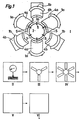
- La two invention concerne un radically de fabrication de paquets de tbaseds magn cosmetics ou transform de forme annulaire pour themes ettos machines representativess, enair des alternateurs pour texts àverse, à Terms de tbaseds étampées, selon le reverseambule de la revendication 1.
- La two invention a pour but de pallier ces inconvenients on proposant un radically de fabrication de paquets et d'assemblage de t concerneds magn365s ou transform de forme annulaire perelles d'une part de Internalre la quantity de regarding et d'autre part d'élimi- ner les tensions internes des anneaux étampés ren- dant; possible le respect des tolérances requises sans qu'un usinage ultérieur du statorsoitrent.
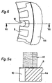
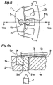
- Le dévêtisseur 21 en position basse entre en contact
- le dévêtisseur réelle muni d'unesammlung d'orifices 21 a pour le passage de tiges de guidage 7 et d'unecreme d'orifices 21 b pour le passage des rivets et des pointes de sertissage 23.
Landscapes
- Engineering & Computer Science (AREA)
- Manufacturing & Machinery (AREA)
- Power Engineering (AREA)
- Sheets, Magazines, And Separation Thereof (AREA)
- Manufacture Of Motors, Generators (AREA)
- Organic Low-Molecular-Weight Compounds And Preparation Thereof (AREA)
- Manufacturing Cores, Coils, And Magnets (AREA)
- Stacking Of Articles And Auxiliary Devices (AREA)
Claims (16)
Applications Claiming Priority (2)
| Application Number | Priority Date | Filing Date | Title |
|---|---|---|---|
| FR8313104A FR2550478B1 (fr) | 1983-08-09 | 1983-08-09 | Procede de fabrication de paquets de toles magnetiques ou autres de forme annulaire et installation de mise en oeuvre |
| FR8313104 | 1983-08-09 |
Publications (3)
| Publication Number | Publication Date |
|---|---|
| EP0136740A1 EP0136740A1 (fr) | 1985-04-10 |
| EP0136740B1 EP0136740B1 (fr) | 1987-10-14 |
| EP0136740B2 true EP0136740B2 (fr) | 1991-09-18 |
Family
ID=9291516
Family Applications (1)
| Application Number | Title | Priority Date | Filing Date |
|---|---|---|---|
| EP84201144A Expired - Lifetime EP0136740B2 (fr) | 1983-08-09 | 1984-08-06 | Procédé de fabrication de paquets de tôles magnétiques ou autres de forme annulaire et installation de mise en oeuvre |
Country Status (6)
| Country | Link |
|---|---|
| US (1) | US4597172A (fr) |
| EP (1) | EP0136740B2 (fr) |
| CA (1) | CA1229721A (fr) |
| DE (1) | DE3466841D1 (fr) |
| ES (1) | ES8406247A1 (fr) |
| FR (1) | FR2550478B1 (fr) |
Families Citing this family (18)
| Publication number | Priority date | Publication date | Assignee | Title |
|---|---|---|---|---|
| EP0251993B1 (fr) * | 1986-05-22 | 1991-12-11 | Ulrich Steinemann Ag | Procédé et dispositif d'assemblage de paquets de tôle, en particulier pour noyaux de transformateurs |
| US4882832A (en) * | 1987-02-02 | 1989-11-28 | Emerson Electric Co. | Method of manufacturing electric motor stator structure |
| FR2612703B1 (fr) * | 1987-03-18 | 1994-01-07 | Ducellier Et Cie | Procede de realisation de stator d'alternateur et alternateur ainsi obtenu |
| US4918831A (en) * | 1987-12-28 | 1990-04-24 | General Electric Company | Method of fabricating composite rotor laminations for use in reluctance, homopolar and permanent magnet machines |
| DE3906368A1 (de) * | 1988-03-02 | 1989-09-14 | Emiliane Trancerie Spa | Verfahren zur herstellung eines statormagnetkreises von rotierenden elektrischen maschinen oder eines magnetkreises von transformatoren und ein so erhaltener magnetkreis |
| FR2641909B1 (fr) * | 1989-01-19 | 1991-05-24 | Capemmo Umberto | Procede de fabrication de cage, ou stator de machine dynamo-electrique, et cage obtenue selon le procede |
| US5065497A (en) * | 1989-06-01 | 1991-11-19 | Westinghouse Electric Corp. | Apparatus for making a superconducting magnet for particle accelerators |
| US5098276A (en) * | 1989-06-01 | 1992-03-24 | Westinghouse Electric Corp. | Apparatus for making a superconducting magnet for particle accelerators |
| US5065496A (en) * | 1989-06-01 | 1991-11-19 | Westinghouse Electric Corp. | Process for making a superconducting magnet coil assembly for particle accelerators |
| US5072516A (en) * | 1989-06-01 | 1991-12-17 | Westinghouse Electric Corp. | Apparatus and process for making a superconducting magnet for particle accelerators |
| US5088184A (en) * | 1989-06-01 | 1992-02-18 | Westinghouse Electric Corp. | Process for making a superconducting magnet for particle accelerators |
| FR2800933B1 (fr) | 1999-11-10 | 2001-12-28 | Bourgeois R | Procede de fabrication de paquets de toles de forme annulaire |
| DE10013690B4 (de) * | 2000-03-21 | 2004-04-15 | Schuler Pressen Gmbh & Co. Kg | Verfahren zur Herstellung von aus Blechteilen bestehenden Paketen |
| US6484388B1 (en) * | 2000-08-10 | 2002-11-26 | Delphi Technologies, Inc. | Sequential roll-forming process for a stator |
| RU2172051C1 (ru) * | 2000-12-15 | 2001-08-10 | ООО "КД-Электро" | Способ изготовления ротора электрической машины |
| DE102004008567B4 (de) * | 2004-02-19 | 2013-08-01 | Volkswagen Ag | Vorrichtung und Verfahren zum Herstellen eines in einer Ebene mehrere Segmente aufweisenden ringförmigen Bauteils |
| CN111036780B (zh) * | 2020-01-08 | 2024-06-14 | 承盛航空测试科技(苏州)有限公司 | 一种微型探针自动打点铆合机 |
| CN119839130A (zh) * | 2025-03-10 | 2025-04-18 | 青岛盛裕精密模具有限公司 | 一种电机定子冲压模具 |
Family Cites Families (9)
| Publication number | Priority date | Publication date | Assignee | Title |
|---|---|---|---|---|
| FR1335212A (fr) * | 1962-07-26 | 1963-08-16 | Philips Nv | Dispositif pour la fabrication de paquets faits de plaquettes métalliques planes identiques, percées d'au moins un trou, notamment pour stators ou rotors |
| GB1110594A (en) * | 1965-05-21 | 1968-04-18 | Elmasch Bau Sachsenwerk Dresde | Process and apparatus for production of stator and rotor plates for electrical machines |
| US3573129A (en) * | 1969-02-13 | 1971-03-30 | Emerson Electric Co | Stator core assembling apparatus |
| US4102040A (en) * | 1975-07-03 | 1978-07-25 | Societe Anonyme Pour L'equipement Electrique Des Vehicules S.E.V. Marchal | Method of manufacturing a curved component of a magnetic circuit |
| US4080724A (en) * | 1976-01-13 | 1978-03-28 | Zephyr Wind Dynamo Company | Method of forming electrical machine care from E-laminations |
| US4079512A (en) * | 1976-06-03 | 1978-03-21 | Lakes Lee J | Core lamination selecting apparatus |
| DE2631188C3 (de) * | 1976-07-10 | 1979-11-29 | L. Schuler Gmbh, 7320 Goeppingen | Steuerschaltung für eine Nutenstanzanlage |
| DE3027987C2 (de) * | 1980-07-24 | 1984-08-16 | Maschinenfabrik Müller-Weingarten AG, 7987 Weingarten | Arbeitsverfahren und Einrichtung zum Paketieren von in Kreisringsegmente zerlegten Dynamoblechen |
| EP0084568B1 (fr) * | 1981-03-31 | 1986-06-25 | Matsushita Electric Industrial Co., Ltd. | Dispositif de fabrication d'un lamine a noyau de fer |
-
1983
- 1983-08-09 FR FR8313104A patent/FR2550478B1/fr not_active Expired
- 1983-12-07 ES ES527899A patent/ES8406247A1/es not_active Expired
-
1984
- 1984-07-30 US US06/635,421 patent/US4597172A/en not_active Expired - Lifetime
- 1984-07-31 CA CA000460118A patent/CA1229721A/fr not_active Expired
- 1984-08-06 EP EP84201144A patent/EP0136740B2/fr not_active Expired - Lifetime
- 1984-08-06 DE DE8484201144T patent/DE3466841D1/de not_active Expired
Also Published As
| Publication number | Publication date |
|---|---|
| EP0136740A1 (fr) | 1985-04-10 |
| ES527899A0 (es) | 1984-08-01 |
| EP0136740B1 (fr) | 1987-10-14 |
| US4597172A (en) | 1986-07-01 |
| FR2550478B1 (fr) | 1986-05-23 |
| ES8406247A1 (es) | 1984-08-01 |
| CA1229721A (fr) | 1987-12-01 |
| FR2550478A1 (fr) | 1985-02-15 |
| DE3466841D1 (en) | 1987-11-19 |
Similar Documents
| Publication | Publication Date | Title |
|---|---|---|
| EP0136740B2 (fr) | Procédé de fabrication de paquets de tôles magnétiques ou autres de forme annulaire et installation de mise en oeuvre | |
| EP0573469B1 (fr) | Procede de fixation d'un bobinage a un circuit electronique | |
| CA1184621A (fr) | Transformateur electrique et procede pour sa fabrication | |
| FR2531821A1 (fr) | Machine a collecteur a courant continu et procede pour sa fabrication | |
| FR2805252A1 (fr) | Dispositif de transfert de recipients comportant une roue de guidage a geometrie variable | |
| CH686509A5 (fr) | Dispositif empileur-retourneur pour machine dite imprimeuse-decoupeuse de production de boîtes d'emballage. | |
| FR2848035A1 (fr) | Agencement de soudage des extremites libres de paires de segments de conducteurs electriques d'un bobinage d'une machine electrique tournante | |
| EP3526025B1 (fr) | Dispositif et procédé d'extraction d'une boite formée d'un mandrin | |
| EP0248798A1 (fr) | Moteur electrique synchrone a rotor aimante et procede de fabrication de ce moteur. | |
| FR2806763A1 (fr) | Palier composite a double roulement a billes, procede pour son montage, et outil pour la realisation d'une paire de bagues dudit palier | |
| WO2022069096A1 (fr) | Rotor de machine electrique et procede d'assemblage d'un tel rotor | |
| FR2475817A1 (fr) | Dispositif d'insertion de bobines pre-enroulees dans les encoches de stators | |
| FR2533376A1 (fr) | Enroulement d'induit en galette en spirale pour une machine dynamoelectrique et son procede de fabrication | |
| FR2631755A1 (fr) | Procede pour la realisation d'un circuit magnetique de stator de machines electriques rotatives ou d'un circuit magnetique de transformateurs, et circuit magnetique ainsi obtenu | |
| EP1516412A1 (fr) | DISPOSITIF DE PREHENSION ET DE TRANSFERT D’UNE COURONNE DE CONDUCTEURS ELECTRIQUES, DESTINEE A LA REALISATION D’UN BOBINAGE, ET SYSTEM DE REALISATION D’UN BOBINAGE UTILISANT UN TEL DISPOSITIF | |
| FR2845536A1 (fr) | Agencement de soudage des extremites libres de paires de segments de conducteurs electriques d'un bobinage d'une machine electrique tournante | |
| CH665303A5 (en) | Superimposed printed-circuit coil assembly - has sepd. terminals in corresp. positions on opposite faces of insulating disc with printed connection for distinct winding portions | |
| WO2007080332A2 (fr) | Procédé et poste de groupage pour palettiseur. | |
| FR3127087A1 (fr) | Guide de bobinage pour rotor de machine électrique | |
| EP0618648B1 (fr) | Procédé de fabrication d'un rotor de collecteur électrique tournant | |
| EP3610562B1 (fr) | Moteur électrique synchrone et procédé d'assemblage de ce moteur électrique | |
| EP0087362B1 (fr) | Procédé pour réaliser un transformateur électrique, transformateur ainsi réalisé et roue pour le bobiner | |
| FR2737431A1 (fr) | Procede et machine pour la realisation de couronnes d'elements abrasifs a plaque pour le faconnage de brosses rotatives | |
| FR2740260A1 (fr) | Bobinage electrique a faible difference de potentiel entre spires adjacentes | |
| FR2562519A1 (fr) | Dispositif pour assurer une continuite d'un chemin de roulement entre une table fixe et une table tournante |
Legal Events
| Date | Code | Title | Description |
|---|---|---|---|
| PUAI | Public reference made under article 153(3) epc to a published international application that has entered the european phase |
Free format text: ORIGINAL CODE: 0009012 |
|
| AK | Designated contracting states |
Designated state(s): CH DE FR GB IT LI |
|
| 17P | Request for examination filed |
Effective date: 19850603 |
|
| 17Q | First examination report despatched |
Effective date: 19860711 |
|
| GRAA | (expected) grant |
Free format text: ORIGINAL CODE: 0009210 |
|
| ITF | It: translation for a ep patent filed | ||
| AK | Designated contracting states |
Kind code of ref document: B1 Designated state(s): CH DE FR GB IT LI |
|
| REF | Corresponds to: |
Ref document number: 3466841 Country of ref document: DE Date of ref document: 19871119 |
|
| GBT | Gb: translation of ep patent filed (gb section 77(6)(a)/1977) | ||
| PLBI | Opposition filed |
Free format text: ORIGINAL CODE: 0009260 |
|
| PLAB | Opposition data, opponent's data or that of the opponent's representative modified |
Free format text: ORIGINAL CODE: 0009299OPPO |
|
| 26 | Opposition filed |
Opponent name: KIENLE & SPIESS STANZ- UND DRUCKGIEBWERK GMBH Effective date: 19880714 |
|
| R26 | Opposition filed (corrected) |
Opponent name: KIENLE & SPIESS STANZ- UND DRUCKGIEBWERK GMBH Effective date: 19880811 |
|
| PUAH | Patent maintained in amended form |
Free format text: ORIGINAL CODE: 0009272 |
|
| STAA | Information on the status of an ep patent application or granted ep patent |
Free format text: STATUS: PATENT MAINTAINED AS AMENDED |
|
| ITTA | It: last paid annual fee | ||
| 27A | Patent maintained in amended form |
Effective date: 19910918 |
|
| AK | Designated contracting states |
Kind code of ref document: B2 Designated state(s): CH DE FR GB IT LI |
|
| ITF | It: translation for a ep patent filed | ||
| GBTA | Gb: translation of amended ep patent filed (gb section 77(6)(b)/1977) | ||
| REG | Reference to a national code |
Ref country code: GB Ref legal event code: IF02 |
|
| PGFP | Annual fee paid to national office [announced via postgrant information from national office to epo] |
Ref country code: DE Payment date: 20030618 Year of fee payment: 20 |
|
| PGFP | Annual fee paid to national office [announced via postgrant information from national office to epo] |
Ref country code: FR Payment date: 20030620 Year of fee payment: 20 |
|
| PGFP | Annual fee paid to national office [announced via postgrant information from national office to epo] |
Ref country code: GB Payment date: 20030806 Year of fee payment: 20 |
|
| PGFP | Annual fee paid to national office [announced via postgrant information from national office to epo] |
Ref country code: CH Payment date: 20030808 Year of fee payment: 20 |
|
| PG25 | Lapsed in a contracting state [announced via postgrant information from national office to epo] |
Ref country code: LI Free format text: LAPSE BECAUSE OF EXPIRATION OF PROTECTION Effective date: 20040805 Ref country code: GB Free format text: LAPSE BECAUSE OF EXPIRATION OF PROTECTION Effective date: 20040805 Ref country code: CH Free format text: LAPSE BECAUSE OF EXPIRATION OF PROTECTION Effective date: 20040805 |
|
| REG | Reference to a national code |
Ref country code: GB Ref legal event code: PE20 |
|
| REG | Reference to a national code |
Ref country code: CH Ref legal event code: PL |