EP0087362B1 - Procédé pour réaliser un transformateur électrique, transformateur ainsi réalisé et roue pour le bobiner - Google Patents
Procédé pour réaliser un transformateur électrique, transformateur ainsi réalisé et roue pour le bobiner Download PDFInfo
- Publication number
- EP0087362B1 EP0087362B1 EP83400328A EP83400328A EP0087362B1 EP 0087362 B1 EP0087362 B1 EP 0087362B1 EP 83400328 A EP83400328 A EP 83400328A EP 83400328 A EP83400328 A EP 83400328A EP 0087362 B1 EP0087362 B1 EP 0087362B1
- Authority
- EP
- European Patent Office
- Prior art keywords
- core
- tube
- insulating tube
- transformer
- slot
- Prior art date
- Legal status (The legal status is an assumption and is not a legal conclusion. Google has not performed a legal analysis and makes no representation as to the accuracy of the status listed.)
- Expired
Links
- 238000004804 winding Methods 0.000 title claims abstract description 62
- 238000004519 manufacturing process Methods 0.000 title claims abstract description 9
- 238000000034 method Methods 0.000 claims abstract description 20
- 230000008569 process Effects 0.000 claims abstract description 11
- 229920003023 plastic Polymers 0.000 claims abstract description 8
- 239000004033 plastic Substances 0.000 claims abstract description 8
- 230000008878 coupling Effects 0.000 claims description 11
- 238000010168 coupling process Methods 0.000 claims description 11
- 238000005859 coupling reaction Methods 0.000 claims description 11
- 238000009413 insulation Methods 0.000 description 4
- 239000011111 cardboard Substances 0.000 description 3
- 239000000123 paper Substances 0.000 description 3
- 125000006850 spacer group Chemical group 0.000 description 3
- 229910052782 aluminium Inorganic materials 0.000 description 2
- XAGFODPZIPBFFR-UHFFFAOYSA-N aluminium Chemical compound [Al] XAGFODPZIPBFFR-UHFFFAOYSA-N 0.000 description 2
- 230000008901 benefit Effects 0.000 description 2
- 238000000605 extraction Methods 0.000 description 2
- 238000009434 installation Methods 0.000 description 2
- 239000000463 material Substances 0.000 description 2
- 229910052751 metal Inorganic materials 0.000 description 2
- 239000002184 metal Substances 0.000 description 2
- 230000007935 neutral effect Effects 0.000 description 2
- 230000009466 transformation Effects 0.000 description 2
- 241000422252 Cales Species 0.000 description 1
- RYGMFSIKBFXOCR-UHFFFAOYSA-N Copper Chemical compound [Cu] RYGMFSIKBFXOCR-UHFFFAOYSA-N 0.000 description 1
- 239000000853 adhesive Substances 0.000 description 1
- 230000001070 adhesive effect Effects 0.000 description 1
- 238000005452 bending Methods 0.000 description 1
- 230000007547 defect Effects 0.000 description 1
- 238000010586 diagram Methods 0.000 description 1
- 239000012212 insulator Substances 0.000 description 1
- 230000004048 modification Effects 0.000 description 1
- 238000012986 modification Methods 0.000 description 1
- 239000011087 paperboard Substances 0.000 description 1
- 230000002093 peripheral effect Effects 0.000 description 1
- 230000037452 priming Effects 0.000 description 1
- 238000005096 rolling process Methods 0.000 description 1
Images


Classifications
-
- H—ELECTRICITY
- H01—ELECTRIC ELEMENTS
- H01F—MAGNETS; INDUCTANCES; TRANSFORMERS; SELECTION OF MATERIALS FOR THEIR MAGNETIC PROPERTIES
- H01F5/00—Coils
- H01F5/02—Coils wound on non-magnetic supports, e.g. formers
-
- H—ELECTRICITY
- H01—ELECTRIC ELEMENTS
- H01F—MAGNETS; INDUCTANCES; TRANSFORMERS; SELECTION OF MATERIALS FOR THEIR MAGNETIC PROPERTIES
- H01F41/00—Apparatus or processes specially adapted for manufacturing or assembling magnets, inductances or transformers; Apparatus or processes specially adapted for manufacturing materials characterised by their magnetic properties
- H01F41/02—Apparatus or processes specially adapted for manufacturing or assembling magnets, inductances or transformers; Apparatus or processes specially adapted for manufacturing materials characterised by their magnetic properties for manufacturing cores, coils, or magnets
- H01F41/04—Apparatus or processes specially adapted for manufacturing or assembling magnets, inductances or transformers; Apparatus or processes specially adapted for manufacturing materials characterised by their magnetic properties for manufacturing cores, coils, or magnets for manufacturing coils
- H01F41/06—Coil winding
- H01F41/098—Mandrels; Formers
Definitions
- the present invention relates to a method for producing a single-phase or polyphase electrical transformer more particularly of the type in which the magnetic circuit defines at least one rectangular window.
- the invention also relates to a transformer produced according to the method below.
- the high and low voltage electrical circuits are wound around one or more insulating tubes, each in turn surrounding a magnetic core constituted by one of the branches of the magnetic circuit.
- each circuit can have its core and its insulating tube or else there is on the contrary only one core for each phase.
- Certain advantageous methods for producing such transformers do not make it possible either to produce the magnetic circuit around the electrical coils, or to thread the electrical circuits onto the magnetic cores at a certain stage in the production of the magnetic circuit. This is the case if the magnetic circuit with rectangular window consists of one or more strips of sheet metal rolled around the magnetic windows. According to such manufacturing methods, it is necessary to wind the electrical circuits around the magnetic core once the magnetic circuit is finished.
- US Pat. No. 2,968,445 teaches to set up around the core a thin toothed wheel carrying a cylindrical end piece surrounding the core.
- the gear-tip assembly is assembled from two halves along an axial joint plane.
- the toothed wheel being placed at one of the ends of the core, several layers of insulating paper are rolled around the end piece to make the insulating tube, then the electrical circuits are wound around the insulating tube.
- the two halves of the toothed wheel are then disassembled, and the latter is removed by axially extracting the half-ends from the insulating tube.
- the object of the invention is to remedy these drawbacks by proposing a method according to which the electrical windings are easy to install on the magnetic circuit and occupying almost the entire length of the core (s).
- the invention thus relates to a method for manufacturing a transformer comprising a magnetic frame comprising at least one core and at least one cylinder head which together define at least one substantially rectangular window, at least one high voltage electrical circuit and one low voltage electrical circuit.
- the magnetic circuit is produced, an insulating tube is placed around the core, at least one of the ends of which is detachably coupled to a removable drive wheel, and the electrical coils are wound by causing the rotation of the insulating tube via the drive wheel.
- the method is characterized in that one starts from an insulating plastic tube split along at least one line directed substantially axially, in that it spreads the slot to pass the magnetic core to the inside the tube, in that the slot is closed, and in that at this stage only, the drive wheel is put in place around the core by mechanically coupling it to the annular end of the insulating tube.
- the installation of the insulating tube is considerably simplified and it is both more rigid and better insulator. It is no longer necessary for the drive wheel to have a nozzle engaged inside the tube, so that at the end of winding, the drive wheel is easy to extract, and it is not necessary to provide additional core length for this purpose. The length of the core is therefore almost entirely available for windings.
- the transformer produced according to the above method and comprising at least one core and at least one cylinder head which together define at least one substantially rectangular window, at least one high voltage electrical circuit and at least one low voltage electrical circuit wound around at least one insulating tube placed around the core is characterized in that the insulating tube is made of plastic and has a single slot directed substantially axially, and can move apart elastically to allow passage the magnetic core through the slot.
- the insulating tube can thus be produced in one piece and its installation does not require any fixing operation.
- the wheel for rotating the insulating tube for implementing the method comprising two half-wheels intended to be assembled around a core belonging to a frame magnetic of the transformer, and to be coupled therein in rotation with an insulating tube intended to receive at least one electrical circuit of the transformer, is characterized in that on its face directed towards the core, said wheel has a bearing and centering surface on the insulating tube, an axial stop for the insulating tube, and means for rotationally coupling with the insulating tube.
- the toothed wheel simultaneously ensures the axial and radial positioning and the rotation drive of the insulating tube.
- the three-phase transformer is of the plane magnetic frame type 1 comprising three vertical rectilinear cores 2, the lower and upper ends of which are connected respectively by an upper magnetic yoke 3 and a lower magnetic yoke 4.
- This structure defines between the three cores 2 two rectangular magnetic windows 6.
- the magnetic frame is produced in a known manner from rolled strips of magnetic sheet. It comprises a ring 7 rolled around each window 6 and a peripheral ring 8 surrounding the two rings 7 at the same time.
- Each ring 7 or 8 having a semi-octagonal section, each ring 2 and each cylinder head 3 or 4 has the same octagonal section.
- each insulating tube 9 is arranged co-axially and at a slight distance around each core 2.
- each insulating tube 9 carries a low voltage winding 11 made of a strip of aluminum and a high voltage winding 13 made of copper wire, coaxial with the tube 9 and the core 2.
- the two windings 11 and 13 extend over almost the entire length of the core 2, the high voltage winding 13 being outside.
- an annular insulating spacer of known type not shown, which allows the circulation of the insulating oil in the axial direction between the windings.
- the active part of the transformer that is to say the assembly constituted by the frame 1 and the electrical windings 11, 13 is installed in a tank 14 containing insulating oil closed by an upper cover 16, and in which the nuclei 2 are vertical.
- the bottom 17 of the tank carries four longitudinal battens 18 and two transverse battens 19 intended to receive between them the magnetic frame 1 and to position it both in the longitudinal and transverse direction.
- the same device is found under the cover 16 where rubber blocks 21 are also interposed between each pair of cleats 18 and the frame 1 to ensure the elastic positioning of the latter in the vertical direction.
- the insulating tube 9 is made of plastic and is split along one of its degenerators 22.
- the profile of the slot 22 is sinuous, more precisely in step, so as to lengthen the electrical leakage line constituted by the slot sufficiently to avoid any possibility of priming between the electrical windings and the magnetic core 2.
- the tube 9 has a thinning forming a hinge.
- the insulating tube has two tenons 26 arranged on either side of the slot 22 and adjacent to it. This. Each tenon 26 has on the side of the slot 22 a face 27 carried by a plane passing through the axis of the tube 22, so that the slot 22 is closed, the two tenons 26 of one end are joined. Seen from above, they then together have a substantially semi-circular shape. As shown in FIG. 4, each annular end of the tube 9 extends axially from the windings 11 and 13 over a length equal to the thickness of the studs 26. In service, these are arranged laterally against the internal winding 11. The face 27 of the pins 26 is in a plane perpendicular to the plane of the frame 1.
- Each annular end of the tube 9 is associated with an annular shim 28 or 29 (FIG. 4) interposed between the annular end of the electrical circuits 11, 13 and the adjacent magnetic yoke 3 or 4.
- the shim 28, taken as an example, is shown in a very simplified manner in FIGS. 8 and 9.
- the shim 28 comprises two half-shims 31, 32 of generally semi-circular shape.
- the joint plane 33 between the half shims 31 and 32 is carried by the median longitudinal plane CC of the frame 1 (FIG. 9).
- the shim On its annular face directed towards the core 2, the shim has a bearing surface 34 whose contour corresponds to the profile of the core 2, so that when the half-shims 31, 32 are assembled around the latter, the shim 28 has no freedom of radial or rotary movement relative to the frame 1.
- the surface 34 is octagonal like the core 2.
- the oblique faces 36 of the surface 34 are recessed to avoid contact with the core 2, which simplifies the centering problems. Only the faces of the surface 34 which are parallel or perpendicular to the plane CC are in contact with the core 2 and ensure positioning. In service, the surface 34 is located between the annular end of the tube 9 and the adjacent cylinder head 3 or 4.
- the wedge 28 also has on its face directed towards the core a second bearing surface 37 closer axially to the windings 11 and 13 than the face 34.
- the face 37 which is further from the axis of the core 2 than the face 34, is connected thereto by a shoulder 38.
- the face 37 ' which is cylindrical and has a diameter equal to the external diameter of the tube 9, bears on the external face of the latter and more precisely on the part of the tube 9 which protrudes from the windings 11 and 13.
- the width of the surface 37 is equal to the length of the tube 9 which protrudes from the windings 11 and 13.
- the half-shim 31 In position offset by 90 ° relative to the joint plane 33, the half-shim 31 has a semi-circular recess 39 whose shape corresponds to that of the two studs 26 assembled.
- the thickness e of the wedge 28 is equal to the distance separating the windings 11 to 13 from the adjacent cylinder head 3 or 4 in service.
- each half-shim 31 or 32 comprises a web 43 which is substantially plane in the zone 40 bearing against the magnetic yoke 3 or 4.
- the veil 43 On its face directed towards the windings 11, 13 , the veil 43 carries fins 44 located on either side of the central opening of the wedge, and oriented perpendicular to the plane CC. On this same face, the veil 43 also carries fins 46 parallel to the fins 44 and extending from the central opening of the wedge 28.
- the central opening of the wedge 28 is delimited by an octagonal cutout of the web 43, the edge of which constitutes the surface 34 of bearing against the magnetic core 2.
- the surface 37 for supporting the wedge 28 on the tube 9 is produced at the end of the fins 46 directed towards the central opening of the wedge 28.
- each of these ends forms a staircase constituted by a part of the face 36, a part of the shoulder 38 and a part of the surface 37.
- the surface 37 further comprises a cylindrical sector in the middle of which the notch 39 is formed.
- the veil 43 carries on its face turned towards the adjacent cylinder head 3 or 4, fins 48 oriented obliquely with respect to the plane CC.
- the orientation of the fins 48 carried by one of the half-shims 31, 32 on one side of the opening of the shim 28 is symmetrical with respect to the plane CC of that carried by the other half-shim 31 or 32 on the same side of the central opening of the shim 28, and is identical to that of the fins 48 carried by the other half-shim 31 or 32 on the other side of the central opening of the shim 28.
- the fins 48 are lying in the direction of extraction of the half-shims, so that if one tends to extract the half-shims, they oppose this extraction by bending against the adjacent magnetic yoke 3 or 4.
- the web 43 is curved (FIGS. 12a to 14), in the direction opposite to the windings 11, 13.
- the two half-shims 31 and 32 are assembled according to a stepped joint plane, for the benefit of the robustness and the precision of the assembly.
- the fins 44 carried by each half-shim 31 or 32 are each aligned with one of the fins 44 carried by the other half-shim.
- the fin 44 closest to the central opening of the wedge 28, called fin 44a is thicker than the others and traversed by a bore, threaded with respect to the half-wedge 32, which makes it possible to screw together the two half shims 31, 32 by means of superpolyamide screws.
- the half-shims 31, 32 have a rectangular notch 49 intended to allow the lateral face of the windings 11 to 13 to appear and to allow the connections to exit.
- Each half-wedge 31 or 32 carries on the side opposite to the windings 11 to 13, a U-shaped mount 51 attached by its edge to the veil 43. The central part of the mount is located between the central opening of the wedge 28 and the notch 49, while its two arms are directed opposite the central opening.
- Each of the legs of the frame 51 carries two snap holes 52 ( Figure 12a).
- the mount 51 of the half-shim 32 is used to carry two supports 53, 54 intended in turn to carry coupling members between the low voltage windings of the transformer. As shown in FIG.
- the support 53 carries a blade 56 electrically connected to the internal end of the winding 11.
- the end of the support 53 also carries a blade 57 electrically connected to the blade 56 and connecting the latter to a low voltage phase terminal 58 arranged on one of the end side walls of the tank 14 ( Figure 2).
- Two other blades 59 surrounded by insulation ( Figure 4) are mounted against the blade 57 and each connect the winding 11 assigned to one of the other two cores 2 to a respective phase terminal arranged next to the terminal 58 ( Figure 2).
- the support 54 carries a blade 62 connected to the other end of the winding 11 and a longitudinal blade 63 electrically coupling the blades 62 of the three windings 11 of the transformer.
- the blade 63 is electrically connected to a neutral terminal 64 fitted at the end of the transformer below the terminals 58 and 61 (FIG. 1).
- the frame 51 of the half-block 31 does not carry any accessories. Through the notch 49 of this half-shim passes one of the end wires 66 of the high-voltage winding 13. Each of the wires 66 is connected directly to a high-voltage phase terminal 67 (FIG. 4) arranged in the cover 16 of tank 14 just above the corresponding notch 49.
- the shim 29 carries a housing 68 forming part of a switching device 69 making it possible to adjust the transformation ratio of the transformer.
- the device 69 is shown diagrammatically in FIG. 17 in which we see the three windings 13 coupled in a star between each of the terminals 67 and a conductive rod 71 carrying a contact 72 opposite each of the windings 13.
- each winding 13 On the side of this rod, each winding 13 carries three output contacts 73, one connected to the end of winding 13, the other connected to a turn located below this end and the third to a turn even further from the end of the winding.
- the contacts 73 are arranged for each winding 13 in a housing 68.
- the conductive rod 71 is slidably mounted between each of these housings 68 and a cover 74 which closes it ( Figure 16). In service, the rod is located between the windings 11, 13 and the bottom of the tank, next to the cylinder head 4.
- the rack 71 is connected to a cable 76 mounted in a sheath 77 and connected to a rotary control button 78 placed under the terminal 64 ( Figure 1).
- the rod 71 carries a rack 79 directed towards the bottom of the tank 14, which cooperates with a toothed wheel 81 to which is attached the end of a helical spring 82 ( Figure 4) whose other end is fixed to the housing 68.
- the spring 82 permanently biases the pinion 81 in the direction of the tension of the cable 76, the adjustments being locked by an appropriate device of known type provided in the control button 78 (FIG. 1).
- An insulating tube 9 is then placed around one of the cores 2, drawing aside the slot 22, passing the core 2 through the slot 22 and then closing the slot 22 when the core 2 is in the tube 9.
- the hinge 23 allows the semi-cylindrical half-shells constituting the tube 9 to pivot relative to one another during these operations.
- a drive toothed wheel 83 (FIGS. 7 and 10) is then placed at each end of the tube 9 formed of two half-wheels separated by a joint plane passing substantially through the axis of the wheel 83.
- the two half wheels are intended to be screwed together with the core 2 and the end of the tube 9 to which the wheel 83 is assigned.
- the wheel 83 is provided with two bores 88 which pass through the joint plane 87 between the half-wheels 84 and 85.
- the bores 88 are tapped in the half-wheel 85 (the teeth of which are not shown) and are embedded in a well 89 opening into the teeth (shown in part only) of the half-wheel 84.
- the wheel 83 On its annular face directed towards the core 2, the wheel 83 has a cylindrical surface 91 intended to bear all around the annular end of the tube 9.
- the axial dimension of the surface 91 corresponds to the length of tube 9 which must exceed windings 11, 13.
- the half-wheel 84 In position offset by 90 ° relative to the joint plane 87, the half-wheel 84 has a notch 92 intended to receive the two studs 26 joined.
- the half-wheel 85 has, opposite the notch 92, a radial groove 93 going from the surface 91 to the toothed periphery of the wheel 83.
- the surface 91 is bordered by a flange 94 serving as a stop for the insulating tube 9.
- three toothed satellites 96 are installed around each of them.
- one of the satellites 96 is coupled to a motor 97 while the two others simply ensure the centering of the wheels 83.
- one carries on the side opposite to the tube 9 a collar 98 intended to position the wheels 83 axially.
- the conductive strip 99 is then brought to the end of which a transverse conductive strip has been fixed which constitutes on each side of the strip 99 a blade 56 which is engaged in the groove 93 of the adjacent drive wheel 83.
- One of the blades 56 will then constitute the phase contact blade of the winding (see FIG. 4), while the other (not visible in FIG. 10), which can be much shorter, is used only for driving. of the band 99 by the wheels 83.
- the strip 99 consists of an aluminum tape covered with a sheet of insulating paper intended to electrically isolate the turn in progress from the next turn.
- the neutral coupling blade 63 (figure 4) is fixed at the end of it, which is engaged in the groove 93 of the wheel 83 (figure 10).
- plastic insulating spacer (not shown) of known type, analogous to a ladder that would have bent to bring these two ends.
- the winding 13 is then produced around this spacer 13 in a manner which, as regards the arrangement of the turns and their mutual insulation, is analogous to that described in US Pat. No. 2,968,445.
- the contacts 73 are connected where provided.
- the wheels 83 are dismantled, and the windings are carried out in the same way around the other two cores 2.
- the transformer which has just been described is thus particularly easy to produce, light, compact and efficient.
- the insulating tube 9 is very easy to put in place, and also makes it possible to provide only a very small space between the winding 11 and the core 2.
- this process for producing the windings at using the tube 9 almost the entire length of the cores 2 is occupied by the windings.
- the wedges 28 and 29, which cleverly cooperate with the tube 9 alone provide all the functions of positioning the windings relative to the magnetic frame 1.
- the very precise positioning ensured in this way makes it possible to reduce the safety margins provided for the spaces insulation, which is advantageous in lightness and performance.
- thermo-siphon between the windings Thanks to the fins 44 and 46, as well as the curved parts of the web 43 playing the role of oil deflectors, a real circulation of oil can be established by thermo-siphon between the windings.
- the insulating tube prefferably carry means for rotationally coupling with the drive wheels and chocks.
- This coupling could for example be effected by a thin projection carried by the wheels and the wedges and engaging in the slot 22.
- the insulating tube can consist of two completely separate shells. On the contrary, it may only consist of an elastic shell without hinge.
Landscapes
- Engineering & Computer Science (AREA)
- Power Engineering (AREA)
- Manufacturing & Machinery (AREA)
- Insulating Of Coils (AREA)
- Coils Of Transformers For General Uses (AREA)
- Arrangements For Transmission Of Measured Signals (AREA)
Description
- La présente invention concerne un procédé pour réaliser un transformateur électrique monophasé ou polyphasé plus particulièrement du genre dans lequel le circuit magnétique définit au moins une fenêtre rectangulaire.
- L'invention concerne également un transformateur réalisé selon le procédé ci-dessous.
- Elle concerne aussi une roue pour bobiner ce transformateur selon le=procédé précité.
- Dans les transformateurs visés par l'invention, les circuits électriques haute et basse tension sont bobinés autour d'un ou plusieurs tubes isolants entourant à leur tour chacun un noyau magnétique constitué par l'une des branches du circuit magnétique. Selon les réalisations, chaque circuit peut avoir son noyau et son tube isolant ou bien il n'y a au contraire qu'un noyau pour chaque phase.
- Certains procédés avantageux pour réaliser de tels transformateurs, ne permettent ni de réaliser le circuit magnétique autour des bobinages électriques, ni d'enfiler les circuits électriques sur les noyaux magnétiques à un certain stade de la réalisation du circuit magnétique. C'est le cas si le circuit magnétique à fenêtre rectangulaire consiste en une ou plusieurs bandes de tôle roulées autour des fenêtres magnétiques. Selon de tels procédés de fabrication, il est nécessaire de bobiner les circuits électriques autour du noyau magnétique une fois que le circuit magnétique est terminé.
- Pour réaliser le circuit électrique, le brevet US 2 968 445 enseigne de mettre en place autour du noyau une roue dentée mince portant un embout cylindrique entourant le noyau. L'ensemble roue dentée-embout est assemblé à partir de deux moitiés selon un plan de joint axial. La roue dentée étant placée à l'une des extrémités du noyau, on roule autour de l'embout plusieurs couches de papier isolant pour réaliser le tube isolant, puis on bobine les circuits électriques autour du tube isolant. On désassemble ensuite les deux moitiés de la roue dentée, et on ôte celle-ci en extrayant axialement du tube isolant les demi-embouts.
- Ce procédé présente l'inconvénient que le papier ou carton dont est réalisé le tube est, malgré toutes les précautions prises, une matière fragile et manquant de rigidité, susceptible d'être à l'origine de défauts d'isolation et impliquant donc de larges espaces de sécurité entre tube et noyau. On ne voit pourtant pas quelle matière autre que le carton pourrait être mise en oeuvre avec plus de succès dans le cadre d'un tel procédé. En outre, les circuits électriques ne peuvent occuper toute la longueur du noyau. En effet, il faut réserver une certaine longueur pour l'épaisseur de la roue dentée, et encore une longueur supplémentaire permettant ensuite d'extraire l'embout de tube en carton. En outre, la réalisation du tube isolant est peu commode et nécessite des précautions quant à la superposition correcte et serrée des couches de papier.
- Le but de l'invention est de remédier à ces inconvénients en proposant un procédé selon lequel les enroulements électriques soient faciles à mettre en place sur le circuit magnétique et occupant la quasi-totalité de la longueur du ou des noyaux.
- L'invention vise ainsi un procédé pour fabriquer un transformateur comportant un cadre magnétique comprenant au moins un noyau et au moins une culasse qui définissent ensemble au moins une fenêtre sensiblement rectangulaire, au moins un circuit électrique haute tension et un circuit électrique basse tension. Selon ce procédé, on réalise le circuit magnétique, on place autour du noyau un tube isolant dont l'une des extrémités au moins est couplée de façon amovible à une roue d'entraînement démontable, et on bobine les spires électriques en provoquant la rotation du tube isolant par l'intermédiaire de la roue d'entraînement.
- Suivant l'invention, le procédé est caractérisé en ce qu'on part d'un tube isolant en matière plastique fendu selon au moins une ligne dirigée sensiblement axialement, en ce qu'on écarte la fente pour faire passer le noyau magnétique à l'intérieur du tube, en ce qu'on referme la fente, et en ce qu'à ce stade seulement, on met en place la roue d'entraînement au tour du noyau en l'accouplant mécaniquement à l'extrémité annulaire du tube isolant.
- Ainsi, la pose du tube isolant est considérablement simplifiée et celui-ci est à la fois plus rigide et meilleur isolant. Il n'est plus nécessaire que la roue d'entraînement présente un embout engagé à l'intérieur du tube, de sorte qu'en fin de bobinage, la roue d'entraînement est facile à extraire, et il n'est pas nécessaire de prévoir une longueur supplémentaire de noyau à cet effet. La longueur du noyau est donc disponible en quasi-totalité pour les enroulements.
- Selon un autre aspect de l'invention, le transformateur réalisé selon le procédé ci-dessus et comprenant au moins un noyau et au moins une culasse qui définissent ensemble au moins une fenêtre sensiblement rectangulaire, au moins un circuit électrique haute tension et au moins un circuit électrique basse tension bobinés autour d'au moins un tube isolant placé autour du noyau, est caractérisé en ce que le tube isolant est en matière plastique et présente une fente unique dirigée sensiblement axialement, et peut s'écarter élastiquement pour permettre de faire passer le noyau magnétique par la fente.
- Le tube isolant peut ainsi être réalisé en une seule pièce et sa mise en place ne nécessite aucune opération de fixation.
- Selon un troisième aspect de l'invention, la roue d'entraînement en rotation du tube isolant pour la mise en oeuvre du procédé, comprenant deux demi-roues destinées à être assemblées autour d'un noyau appartenant à un cadre magnétique du transformateur, et à y être couplées en rotation avec un tube isolant destiné à recevoir au moins un circuit électrique du transformateur, est caractérisée en ce que sur sa face dirigée vers le noyau, ladite roue présente une surface d'appui et de centrage sur le tube isolant, une butée axiale pour le tube isolant, et des moyens de couplage en rotation avec le tube isolant.
- Ainsi, même démunie d'embout, la roue dentée assure en même temps le positionnement axial et radial et l'entraînement en rotation du tube isolant.
- D'autres particularités et avantages de l'invention ressortiront encore de la description ci-après.
- Aux dessins annexés, donnés à titre d'exemples non limitatifs :
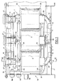
- la figure 1 est une vue en élévation latérale d'un transformateur triphasé, conforme à l'invention, la cuve étant coupée selon un plan parallèle au plan de circuit magnétique ;
- la figure 2 est une vue de dessus du transformateur de la figure 1, le couvercle de la cuve étant ôté ;
- la figure 3 est une vue en bout de la partie active du transformateur des figures 1 et 2, avec coupe de la cuve selon un plan parallèle à celui de la figure ;
- la figure 4 est une vue du transformateur en coupe transversale selon le plan IV-IV de la figure 1, à échelle agrandie ;
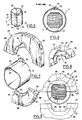
- la figure 5 est une vue en perspective du tube isolant destiné à entourer l'un des noyaux ;
- la figure 6 est une vue en coupe transversale de l'un des noyaux avec son tube isolant ;
- la figure 7 est une vue en perspective éclatée avec arrachement, du tube isolant et d'une roue d'entraînement pour son bobinage ;
- la figure 8 est une vue de dessous schématique en perspective avec arrachement d'une cale de fixation des enroulements ;
- la figure 9 est une vue en coupe à travers l'extrémité de l'un des noyaux, montrant le tube qui l'entoure, ainsi que les deux demi-cales affectées à cette extrémité du tube, l'une de ces demi-cales étant montée, l'autre en cours de montage ;
- la figure 10 est une vue en perspective de l'opération de bobinage du circuit basse tension ;
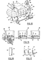
- les figures 11 a et 11b sont des vues de dessous des deux cales affectées à l'extrémité supérieure de l'un quelconque des trois noyaux ;
- les figures 12a et 12b sont des vues en coupe selon le plan XII-XII des figures 11a et 11 b ;
- les figures 13 et 14 sont des vues selon les flèches XIII et XIV des figures 11a et 11b respectivement ;
- la figure 15 est une vue en élévation latérale avec arrachements du dispositif de commutation du transformateur, les couvercles des boîtiers étant ôtés ;
- la figure 16 est une vue en bout de l'un des boîtiers de la figure 15, avec coupe transversale de la tringle de commande ; et
- la figure 17 est un schéma électrique du dispositif de commutation.
- Dans l'exemple représenté aux figures, le transformateur triphasé est du type à cadre magnétique plan 1 comprenant trois noyaux rectilignes verticaux 2 dont les extrémités inférieures et supérieures sont reliées respectivement par une culasse magnétique supérieure 3 et une culasse magnétique inférieure 4. Cette structure définit entre les trois noyaux 2 deux fenêtres magnétiques rectangulaires 6.
- Le cadre magnétique est réalisé de façon connue à partir de bandes de tôle magnétique roulées. Il comprend un anneau 7 roulé autour de chaque fenêtre 6 et un anneau périphérique 8 entourant les deux anneaux 7 à la fois. Chaque anneau 7 ou 8 ayant une section semi-octogonale, chaque anneau 2 et chaque culasse 3 ou 4 a la même section octogonale.
- Comme le montre la figure 4, un tube isolant 9 est disposé co-axialement et à légère distance autour de chaque noyau 2. Compte tenu du couplage électrique du transformateur, chaque tube isolant 9, porte un enroulement basse tension 11 réalisé en bande d'aluminium et un enroulement haute tension 13 réalisé en fil de cuivre, coaxiaux avec le tube 9 et le noyau 2. Les deux enroulements 11 et 13 s'étendent sur la quasi-totalité de la longueur du noyau 2, l'enroulement haute tension 13 se trouvant à l'extérieur. Entre les enroulements 11 et 13 est disposée une entretoise annulaire isolante de type connu, non représentée, qui permet la circulation de l'huile isolante dans le sens axial entre les enroulements.
- La partie active du transformateur, c'est-à-dire l'ensemble constitué par le cadre 1 et les enroulements électriques 11, 13 est installée dans une cuve 14 contenant de l'huile isolante fermée par un couvercle supérieur 16, et dans laquelle les noyaux 2 sont verticaux. Le fond 17 de la cuve porte quatre tasseaux longitudinaux 18 et deux tasseaux transversaux 19 destinés à recevoir entre eux le cadre magnétique 1 et à le positionner aussi bien en direction longitudinale que transversale. Le même dispositif se retrouve sous le couvercle 16 où des blocs en caoutchouc 21 sont en outre interposés entre chaque paire de tasseaux 18 et le cadre 1 pour assurer le positionnement élastique de ce dernier en direction verticale.
- Comme le montre schématiquement la figure 5, le tube isolant 9 est réalisé en matière plastique et est fendu selon l'une de ses dégénératrices 22. Comme le montrent les figure 5 et 6, le profil de la fente 22 est sinueux, plus précisément en gradin, de façon à allonger suffisamment la ligne de fuite électrique constituée par la fente pour éviter toute possibilité d'amorçage entre les enroulements électriques et le noyau magnétique 2.
- Le long de sa génératrice 23 diamétralement opposée à la fente 22, le tube 9 présente un amincissement formant charnière.
- A chacune de ces extrémités annulaires, le tube isolant présente deux tenons 26 aménagés de part et d'autre de la fente 22 et adjacents à celle-ci. Chaque tenon 26 a du côté de la fente 22 une face 27 portée par un plan passant par l'axe du tube 22, de sorte que la fente 22 est fermée, les deux tenons 26 d'une extrémité sont jointifs. Vus de dessus, ils ont alors ensemble une forme sensiblement semi-circulaire. Comme le montre la figure 4, chaque extrémité annulaire du tube 9 dépasse axialement des enroulements 11 et 13 sur une longueur égale à l'épaisseur des tenons 26. En service, ceux-ci sont disposés latéralement contre l'enroulement interne 11. La face 27 des tenons 26 est dans un plan perpendiculaire au plan du cadre 1.
- Chaque extrémité annulaire du tube 9 est associée à une cale annulaire 28 ou 29 (figure 4) interposée entre l'extrémité annulaire des circuits électriques 11, 13 et la culasse magnétique adjacente 3 ou 4. La cale 28, prise comme exemple, est représentée de façon très simplifiée aux figures 8 et 9. La cale 28 comporte deux demi-cales 31, 32 de forme générale semi-circulaire. Dans l'exemple représenté, le plan de joint 33 entre les demi-cales 31 et 32 est porté par le plan longitudinal médian CC du cadre 1 (figure 9).
- Sur sa face annulaire dirigée vers le noyau 2, la cale présente une surface d'appui 34 dont le contour correspond au profil du noyau 2, de sorte que lorsque les demi-cales 31, 32 sont assemblées autour de celui-ci, la cale 28 n'a aucune liberté de mouvement radial ou rotatif par rapport au cadre 1.
- Dans l'exemple représenté, la surface 34 est octogonale comme le noyau 2. Toutefois, les faces obliques 36 de la surface 34 sont en retrait pour éviter le contact avec le noyau 2, ce qui simplifie les problèmes de centrage. Seules les faces de la surface 34 qui sont parallèles ou perpendiculaires au plan CC sont au contact du noyau 2 et assurent le positionnement. En service, la surface 34 se trouve entre l'extrémité annulaire du tube 9 et la culasse 3 ou 4 adjacente.
- La cale 28 présente en outre sur sa face dirigée vers le noyau une seconde surface d'appui 37 plus proche axialement des enroulements 11 et 13 que la face 34. La face 37, qui est plus éloignée de l'axe du noyau 2 que la face 34, est raccordée à celle-ci par un épaulement 38. La face 37' qui est cylindrique et a un diamètre égal au diamètre externe du tube 9, prend appui sur la face externe de celui-ci et plus précisément sur la partie du tube 9 qui dépasse des enroulements 11 et 13. La largeur de la surface 37 est égale à la longueur du tube 9 qui dépasse des enroulements 11 et 13.
- En position décalée de 90° par rapport au plan de joint 33, la demi-cale 31 présente un évidement semi-circulaire 39 dont la forme correspond à celle des deux tenons 26 assemblés.
- Dans la zone comprise entre les deux lignes 41 (figure 9) qui délimitent la zone dans laquelle la cale est interposée entre la bande la plus interne de la culasse 3 ou 4 et les enroulements 11 à 13, l'épaisseur e de la cale 28 est égale à la distance séparant en service les enroulements 11 à 13 de la culasse 3 ou 4 adjacente.
- Les cales 28, 29, réalisées en matière plastique injectée, assurent ainsi à la fois le positionnement axial, le centrage, et l'immobilisation en rotation des enroulements 11 à 13 sur le noyau 2.
- On va maintenant décrire plus en détail une réalisation pratique de la date 28 représentée aux figures 11a à 14.
- Comme le montrent notamment les figures 13 et 14, chaque demi-cale 31 ou 32 comprend un voile 43 qui est sensiblement plan dans la zone 40 d'appui contre la culasse magnétique 3 ou 4. Sur sa face dirigée vers les enroulements 11, 13, le voile 43 porte des ailettes 44 situées de part et d'autre de l'ouverture centrale de la cale, et orientées perpendiculairement au plan CC. Sur cette même face, le voile 43 porte également des ailettes 46 parallèles aux ailettes 44 et s'étendant à partir de l'ouverture centrale de la cale 28.
- L'ouverture centrale de la cale 28 est délimitée par une découpe octogonale du voile 43 dont la tranche constitue la surface 34 d'appui contre le noyau magnétique 2.
- Comme le montrent notamment les figures 11a, 11b, 13 et 14, la surface 37 d'appui de la cale 28 sur le tube 9 est réalisée à l'extrémité des ailettes 46 dirigée vers l'ouverture centrale de la cale 28. A cet effet, chacune de ces extrémités forme un escalier constitué par une partie de la face 36, une partie de l'épaulement 38 et une partie de la surface 37.
- Sur la demi-cale 31 seulement, la surface 37 comprend en outre un secteur cylindrique au milieu duquel est ménagée l'encoche 39.
- Dans la zone 40 de la cale 28, le voile 43 porte sur sa face tournée vers la culasse adjacente 3 ou 4, des ailettes 48 orientées obliquement par rapport au plan CC. L'orientation des ailettes 48 portées par l'une des demi-cales 31, 32 d'un côté de l'ouverture de la cale 28 est symétrique par rapport au plan CC de celle portée par l'autre demi-cale 31 ou 32 du même côté de l'ouverture centrale de la cale 28, et est identique à celle des ailettes 48 portées par l'autre demi-cale 31 ou 32 de l'autre côté de l'ouverture centrale de la cale 28.
- En outre, comme le montrent les figures 13 et 14, les ailettes 48 sont couchées dans le sens de l'extraction des demi-cales, de sorte que si l'on tend à extraire les demi-cales, elles s'opposent à cette extraction en s'arcboutant contre la culasse magnétique adjacente 3 ou 4.
- En dehors de la zone 40, le voile 43 est bombé (figures 12a à 14), en direction opposée aux enroulements 11, 13.
- Comme le montrent les figures 12a et 12b, les deux demi-cales 31 et 32 sont assemblées selon un plan de joint en gradins, au profit de la robustesse et de la précision de l'assemblage. Les ailettes 44 portées par chaque demi-cale 31 ou 32 s'alignent chacune avec l'une des ailettes 44 portée par l'autre demi-cale. L'ailette 44 la plus proche de l'ouverture centrale de la cale 28, appelée ailette 44a, est plus épaisse que les autres et traversée par un alésage, fileté en ce qui concerne la demi-cale 32, qui permet de visser ensemble les deux demi-cales 31, 32 au moyen de vis en superpolyamide.
- Derrière les deux faces de la surface 34 qui sont parallèles au plan CC, les demi-cales 31, 32 présentent une échancrure rectangulaire 49 destinée à laisser apparaître la face latérale des enroulements 11 à 13 et à permettre la sortie des connexions. Chaque demi-cale 31 ou 32 porte du côté opposé aux enroulements 11 à 13, une monture en U 51 attachée par sa tranche au voile 43. La partie centrale de la monture est située entre l'ouverture centrale de la cale 28 et l'échancrure 49, tandis que ses deux bras sont dirigés à l'opposé de l'ouverture centrale. Chacune des branches de la monture 51 porte deux trous d'encliquetage 52 (figure 12a). La monture 51 de la demi-cale 32 sert à porter deux supports 53, 54 destinés à porter à leur tour des organes de couplage entre les enroulements basse tension du transformateur. Comme le montre la figure 4, le support 53, porte une lame 56 reliée électriquement à l'extrémité interne de l'enroulement 11. L'extrémité du support 53 porte également une lame 57 reliée électriquement à la lame 56 et reliant celle-ci à une borne de phase basse tension 58 aménagée sur l'une des parois latérales d'extrémité de la cuve 14 (figure 2). Deux autres lames 59 entourées d'isolant (figure 4) sont montées contre la lame 57 et relient chacune l'enroulement 11 affecté à l'un des deux autres noyaux 2 à une borne de phase respective aménagée à côté de la borne 58 (figure 2).
- Le support 54 porte une lame 62 reliée à l'autre extrémité de l'enroulement 11 et une lame longitudinale 63 couplant électriquement les lames 62 des trois enroulements 11 du transformateur. La lame 63 est reliée électriquement à une borne de neutre 64 aménagée en bout de transformateur en dessous des bornes 58 et 61 (figure 1).
- La monture 51 de la demi-cale 31 ne porte aucun accessoire. Par l'échancrure 49 de cette demi-cale passe l'un des fils d'extrémité 66 de l'enroulement haute tension 13. Chacun des fils 66 est relié directement à une borne de phase haute tension 67 (figure 4) aménagée dans le couvercle 16 de la cuve 14 juste au-dessus de l'échancrure 49 correspondante.
- A l'extrémité des enroulements 11 et 13 dirigés vers le fond de la cuve 14, la cale 29 porte un boîtier 68 faisant partie d'un dispositif de commutation 69 permettant de régler le rapport de transformation du transformateur.
- Le dispositif 69 est représenté schématiquement à la figure 17 dans laquelle on voit les trois enroulements 13 couplés en étoile entre chacune des bornes 67 et une tringle conductrice 71 portant un contact 72 en face de chacun des enroulements 13. Du côté de cette tringle, chaque enroulement 13 porte trois contacts de sortie 73, l'un relié à l'extrémité de l'enroulement 13, l'autre relié à une spire située en-deçà de cette extrémité et le troisième à une spire encore plus éloignée de l'extrémité de l'enroulement. En déplaçant la tringle 71 selon sa direction longitudinale qui correspond à celle du transformateur, on règle le nombre de spires en service dans chaque enroulement et par suite, le rapport de transformation dans le transformateur.
- Comme le montre la figure 15, les contacts 73 sont aménagés pour chaque enroulement 13 dans un boîtier 68. La tringle conductrice 71 est montée à coulisse entre chacun de ces boîtiers 68 et un couvercle 74 qui le ferme (figure 16). En service, la tringle se trouve entre les enroulements 11, 13 et le fond de la cuve, à côté de la culasse 4.
- A l'une de ses extrémités, la crémaillère 71 est reliée à un câble 76 monté dans une gaine 77 et relié à un bouton de commande rotatif 78 placé sous la borne 64 (figure 1).
- A la même extrémité, la tringle 71 porte une crémaillère 79 dirigée vers le fond de la cuve 14, qui coopère avec une roue dentée 81 à laquelle est attachée l'extrémité d'un ressort hélicoïdal 82 (figure 4) dont l'autre extrémité est fixée au boîtier 68. Le ressort 82 sollicite en permanence le pignon 81 dans le sens de la tension du câble 76, les réglages étant verrouillés par un dispositif approprié de type connu prévu dans le bouton de commande 78 (figure 1).
- On va maintenant décrire le procédé de fabrication du transformateur ci-dessus :
- On réalise d'abord par roulage de bandes de tôle magnétiques, les deux anneaux internes 7 puis l'anneau externe 8 de façon à terminer le cadre magnétique 1.
- On place ensuite autour de l'un des noyaux 2 un tube isolant 9 en écartant la fente 22, en faisant passer le noyau 2 par la fente 22 et en refermant ensuite la fente 22 lorsque le noyau 2 est dans le tube 9. La charnière 23 permet aux demi-coquilles semi-cylindriques constituant le tube 9 de pivoter l'une par rapport à l'autre au cours de ces opérations.
- On met ensuite en place à chaque extrémité du tube 9 une roue dentée d'entraînement 83 (figures 7 et 10) formée de deux demi-roues séparées par un plan joint passant sensiblement par l'axe de la roue 83. Les deux demi-roues sont destinées à être vissées l'une à l'autre du noyau 2 et de l'extrémité du tube 9 à laquelle la roue 83 est affectée. A cet effet, de part et d'autre de son ouverture centrale, la roue 83 est munie de deux alésages 88 qui traversent le plan de joint 87 entre les demi-roues 84 et 85. Les alésages 88 sont taraudés dans la demi-roue 85 (dont la denture n'est pas représentée) et sont noyés dans un puits 89 débouchant dans la denture (représentée en partie seulement) de la demi-roue 84.
- Sur sa face annulaire dirigée vers le noyau 2, la roue 83 présente une surface cylindrique 91 destinée à prendre appui tout autour de l'extrémité annulaire du tube 9. La dimension axiale de la surface 91 correspond à la longueur de tube 9 qui doit dépasser des enroulements 11, 13. En position décalée de 90° par rapport au plan de joint 87, la demi-roue 84 présente une encoche 92 destinée à recevoir les deux tenons 26 jointifs. De son côté, la demi-roue 85 présente à l'opposé de l'encoche 92, une saignée radiale 93 allant de la surface 91 au pourtour denté de la roue 83.
- Du côté opposé aux enroulements, la surface 91 est bordée par une collerette 94 servant de butée pour le tube isolant 9.
- Une fois que les deux roues 83 sont en place (fig. 10), on installe autour de chacune d'elles trois satellites dentés 96. Pour chaque roue 83, l'un des satellites 96 est couplé à un moteur 97 tandis que les deux autres assurent simplement le centrage des roues 83. Parmi ceux-ci, l'un porte du côté opposé au tube 9 une collerette 98 destinée à positionner axialement les roues 83.
- On amène ensuite la bande conductrice 99 à l'extrémité de laquelle on a fixé une bande conductrice transversale qui constitue de chaque côté de la bande 99 une lame 56 qu'on engage dans la saignée 93 de la roue d'entraînement 83 adjacente. L'une des lames 56 constituera ensuite la lame de contact de phase de l'enroulement (voir figure 4), tandis que l'autre (non visible sur la figure 10), qui peut être beaucoup plus courte sert uniquement à l'entraînement de la bande 99 par les roues 83.
- La bande 99 est constituée d'un ruban d'aluminium recouvert d'une feuille de papier isolant destinée à isoler électriquement la spire en cours de réalisation de la spire suivante.
- Pour favoriser l'entraînement de la bande 99 par les roues 83, on a collé le départ de celle-ci avec de la bande adhésive 101.
- Quand l'enroulement basse tension 11 est terminé, on fixe à l'extrémité de celui-ci la lame de couplage du neutre 63 (figure 4) que l'on engage dans la saignée 93 de la roue 83 (figure 10).
- On place ensuite autour de l'enroulement 11 une entretoise isolante en matière plastique (non représentée) de type connu, analogue à une échelle qu'on aurait recourbée pour rapprocher ces deux extrémités.
- On réalise ensuite autour de cette entretoise l'enroulement 13 d'une façon qui, en ce qui concerne la disposition des spires et leur isolation mutuelle, est analogue à celle décrite dans le brevet US 2 968 445.
- Au cours de la réalisation de l'enroulement 13, on branche les contacts 73 là où cela est prévu. Une fois l'enroulement 13 terminé, on démonte les roues 83, et on réalise de la même manière les enroulements autour des deux autres noyaux 2.
- On met ensuite en place les cales 28 et 29 autour de chaque noyau 2, on pose les accessoires 53, 54, 68 (figure 4) et on réalise les connexions.
- Le transformateur qui vient d'être décrit est ainsi particulièrement facile à réaliser, léger, compact et performant. En effet, le tube isolant 9 est très facile à mettre en place, et permet en outre de ne prévoir qu'un très faible espace entre l'enroulement 11 et le noyau 2. En outre, grâce à ce procédé de réalisation des enroulements à l'aide du tube 9, la quasi-totalité de la longueur des noyaux 2 est occupée par les enroulements.
- Les cales 28 et 29, qui coopèrent astucieusement avec le tube 9 assurent à elles seules toutes les fonctions de positionnement des enroulements par rapport au cadre magnétique 1. Le positionnement très précis assuré de cette manière permet de réduire les marges de sécurité prévues pour les espaces d'isolation, ce qui est avantageux en légèreté et en performance.
- Grâce aux ailettes 44 et 46, ainsi qu'aux parties bombées du voile 43 jouant le rôle de déflecteurs d'huile, une véritable circulation d'huile peut s'établir par thermo-siphon entre les enroulements.
- Bien entendu, l'invention n'est pas limitée à l'exemple représenté, de nombreux aménagements pouvant être apportés à cet exemple, sans sortir du cadre de l'invention.
- C'est ainsi que l'invention peut s'appliquer à tout transformateur monophase ou polyphasé à fenêtre(s) rectangulaire(s).
- Il n'est pas indispensable que le tube isolant porte des moyens de couplage en rotation avec les roues d'entraînement et les cales. Ce couplage pourrait par exemple s'effectuer par une saillie mince portée par les roues et les cales et s'engageant dans la fente 22.
- Le tube isolant peut être constitué de deux coquilles totalement séparées. Il peut au contraire n'être constitué que d'une coquille élastique sans charnière.
- On pourrait ne prévoir qu'une seule roue d'entraînement.
- On pourrait également prévoir que le circuit haute tension est bobiné directement autour du noyau, tandis que le circuit basse tension est bobiné autour du circuit haute tension.
Claims (9)
Priority Applications (1)
| Application Number | Priority Date | Filing Date | Title |
|---|---|---|---|
| AT83400328T ATE19708T1 (de) | 1982-02-19 | 1983-02-16 | Verfahren zur herstellung eines elektrischen transformators, danach hergestellter transformator, und rad zum wickeln. |
Applications Claiming Priority (2)
| Application Number | Priority Date | Filing Date | Title |
|---|---|---|---|
| FR8202753A FR2522189A1 (fr) | 1982-02-19 | 1982-02-19 | Procede pour realiser un transformateur electrique, transformateur ainsi realise et roue pour le bobiner |
| FR8202753 | 1982-02-19 |
Publications (2)
| Publication Number | Publication Date |
|---|---|
| EP0087362A1 EP0087362A1 (fr) | 1983-08-31 |
| EP0087362B1 true EP0087362B1 (fr) | 1986-05-07 |
Family
ID=9271154
Family Applications (1)
| Application Number | Title | Priority Date | Filing Date |
|---|---|---|---|
| EP83400328A Expired EP0087362B1 (fr) | 1982-02-19 | 1983-02-16 | Procédé pour réaliser un transformateur électrique, transformateur ainsi réalisé et roue pour le bobiner |
Country Status (5)
| Country | Link |
|---|---|
| EP (1) | EP0087362B1 (fr) |
| AT (1) | ATE19708T1 (fr) |
| CA (1) | CA1227326A (fr) |
| DE (2) | DE87362T1 (fr) |
| FR (1) | FR2522189A1 (fr) |
Families Citing this family (3)
| Publication number | Priority date | Publication date | Assignee | Title |
|---|---|---|---|---|
| FR2561033B1 (fr) * | 1984-03-06 | 1988-11-10 | Beisser Jean Claude | Transformateur et son procede de fabrication |
| DE59009023D1 (de) * | 1990-05-21 | 1995-06-08 | Siemens Matsushita Components | Spulenkörper. |
| EP0978851A1 (fr) * | 1994-11-04 | 2000-02-09 | Matsushita Electric Industrial Co., Ltd. | Filtre de ligne |
Family Cites Families (11)
| Publication number | Priority date | Publication date | Assignee | Title |
|---|---|---|---|---|
| GB548548A (en) * | 1941-04-11 | 1942-10-14 | Kolster Brandes Ltd | Moulded coil former |
| FR1007119A (fr) * | 1948-02-26 | 1952-05-02 | Système électromagnétique, ayant notamment la forme d'un transformateur | |
| GB756021A (en) * | 1951-05-04 | 1956-08-29 | Henleys Telegraph Works Co Ltd | Improvements in or relating to bobbins for coil winders |
| US2709051A (en) * | 1951-09-26 | 1955-05-24 | Western Electric Co | Apparatus for coiling filamentary articles |
| US2807874A (en) * | 1954-06-09 | 1957-10-01 | Ona W Morris | Method for making bobbins |
| US2985392A (en) * | 1958-07-10 | 1961-05-23 | Texas Instruments Inc | Apparatus for winding a coil on a closed core |
| FR1266062A (fr) * | 1960-07-22 | 1961-07-07 | Procédé pour former les bobines sur des noyaux de fer | |
| CH451323A (de) * | 1966-03-31 | 1968-05-15 | Siemens Ag | Mehrteiliger Spulenkörper, insbesondere für Relais |
| GB1194805A (en) * | 1967-01-19 | 1970-06-10 | Osaka Onkyo Kabushiki Kaisha | Improvements in or relating to Bobbins |
| FR2177863B1 (fr) * | 1972-03-25 | 1977-04-29 | Philips Nv | |
| JPS5678105A (en) * | 1979-11-30 | 1981-06-26 | Ichiro Ooyama | Bobbin for closed loop core type transformer, etc. |
-
1982
- 1982-02-19 FR FR8202753A patent/FR2522189A1/fr active Granted
-
1983
- 1983-02-16 DE DE198383400328T patent/DE87362T1/de active Pending
- 1983-02-16 AT AT83400328T patent/ATE19708T1/de not_active IP Right Cessation
- 1983-02-16 DE DE8383400328T patent/DE3363342D1/de not_active Expired
- 1983-02-16 EP EP83400328A patent/EP0087362B1/fr not_active Expired
- 1983-02-18 CA CA000421946A patent/CA1227326A/fr not_active Expired
Also Published As
| Publication number | Publication date |
|---|---|
| FR2522189B1 (fr) | 1984-04-20 |
| ATE19708T1 (de) | 1986-05-15 |
| DE3363342D1 (en) | 1986-06-12 |
| DE87362T1 (de) | 1983-12-08 |
| EP0087362A1 (fr) | 1983-08-31 |
| CA1227326A (fr) | 1987-09-29 |
| FR2522189A1 (fr) | 1983-08-26 |
Similar Documents
| Publication | Publication Date | Title |
|---|---|---|
| EP0096058B1 (fr) | Transformateur electrique et procede pour sa fabrication | |
| EP0313514B1 (fr) | Procédé de fabrication d'un stator sans rainures pour moteur électrique et moteur électrique comprenant un stator fabriqué selon le procédé | |
| FR2817679A1 (fr) | Moteur electrique | |
| FR2613884A1 (fr) | Machine electrique comprenant un paquet de toles supportant un enroulement, et procede pour sa fabrication | |
| FR2531821A1 (fr) | Machine a collecteur a courant continu et procede pour sa fabrication | |
| FR2533376A1 (fr) | Enroulement d'induit en galette en spirale pour une machine dynamoelectrique et son procede de fabrication | |
| EP0087362B1 (fr) | Procédé pour réaliser un transformateur électrique, transformateur ainsi réalisé et roue pour le bobiner | |
| FR2561033A1 (fr) | Transformateur et son procede de fabrication | |
| EP0248798B1 (fr) | Moteur electrique synchrone a rotor aimante et procede de fabrication de ce moteur | |
| FR2837909A1 (fr) | Mecanisme reflechissant pour lampe de scene commandee par ordinateur | |
| WO2022069096A1 (fr) | Rotor de machine electrique et procede d'assemblage d'un tel rotor | |
| EP0087363B1 (fr) | Transformateur électrique | |
| EP4402779A1 (fr) | Guide de bobinage pour rotor de machine électrique | |
| WO1991010244A1 (fr) | Transformateur de type torique | |
| FR2465349A1 (fr) | Rotor a poles saillants pour machine dynamo-electrique | |
| FR3065125A1 (fr) | Moteur electrique synchrone et procede d'assemblage de ce moteur electrique | |
| FR2516717A1 (fr) | Rotor a poles saillants pour machine dynamoelectrique avec bobines demontables sans demontage des poles | |
| EP0990295B2 (fr) | Procede de bobinage et bobines pour machine electrique tournantes | |
| FR2492153A1 (fr) | Transformateur de petite taille | |
| FR2816122A1 (fr) | Machine electrique tournante pour vehicule comprenant un induit muni d'un paquet de toles recevant dans chaque encoche un fil interne et un fil peripherique | |
| FR2674062A3 (fr) | Bobinage electrique et son procede de fabrication. | |
| FR2754380A1 (fr) | Procede de bobinage de spires en couches radiales | |
| FR2734960A1 (fr) | Moteur electrique a courant alternatif | |
| FR2707037A1 (en) | Method of fabricating a torus for measuring electric current and torus obtained | |
| FR3128329A1 (fr) | Rotor bobiné pour moteur électrique agencé pour faciliter son assemblage |
Legal Events
| Date | Code | Title | Description |
|---|---|---|---|
| PUAI | Public reference made under article 153(3) epc to a published international application that has entered the european phase |
Free format text: ORIGINAL CODE: 0009012 |
|
| 17P | Request for examination filed |
Effective date: 19830219 |
|
| AK | Designated contracting states |
Designated state(s): AT BE CH DE GB IT LI LU NL SE |
|
| TCAT | At: translation of patent claims filed | ||
| TCNL | Nl: translation of patent claims filed | ||
| ITCL | It: translation for ep claims filed |
Representative=s name: BARZANO' E ZANARDO ROMA S.P.A. |
|
| DET | De: translation of patent claims | ||
| GRAA | (expected) grant |
Free format text: ORIGINAL CODE: 0009210 |
|
| ITF | It: translation for a ep patent filed | ||
| AK | Designated contracting states |
Kind code of ref document: B1 Designated state(s): AT BE CH DE GB IT LI LU NL SE |
|
| REF | Corresponds to: |
Ref document number: 19708 Country of ref document: AT Date of ref document: 19860515 Kind code of ref document: T |
|
| REF | Corresponds to: |
Ref document number: 3363342 Country of ref document: DE Date of ref document: 19860612 |
|
| PLBE | No opposition filed within time limit |
Free format text: ORIGINAL CODE: 0009261 |
|
| STAA | Information on the status of an ep patent application or granted ep patent |
Free format text: STATUS: NO OPPOSITION FILED WITHIN TIME LIMIT |
|
| 26N | No opposition filed | ||
| ITTA | It: last paid annual fee | ||
| PGFP | Annual fee paid to national office [announced via postgrant information from national office to epo] |
Ref country code: GB Payment date: 19930202 Year of fee payment: 11 |
|
| PGFP | Annual fee paid to national office [announced via postgrant information from national office to epo] |
Ref country code: AT Payment date: 19930211 Year of fee payment: 11 |
|
| PGFP | Annual fee paid to national office [announced via postgrant information from national office to epo] |
Ref country code: SE Payment date: 19930215 Year of fee payment: 11 |
|
| PGFP | Annual fee paid to national office [announced via postgrant information from national office to epo] |
Ref country code: CH Payment date: 19930223 Year of fee payment: 11 |
|
| PGFP | Annual fee paid to national office [announced via postgrant information from national office to epo] |
Ref country code: NL Payment date: 19930228 Year of fee payment: 11 |
|
| PGFP | Annual fee paid to national office [announced via postgrant information from national office to epo] |
Ref country code: LU Payment date: 19930310 Year of fee payment: 11 |
|
| PGFP | Annual fee paid to national office [announced via postgrant information from national office to epo] |
Ref country code: BE Payment date: 19930329 Year of fee payment: 11 |
|
| PGFP | Annual fee paid to national office [announced via postgrant information from national office to epo] |
Ref country code: DE Payment date: 19930428 Year of fee payment: 11 |
|
| EPTA | Lu: last paid annual fee | ||
| PG25 | Lapsed in a contracting state [announced via postgrant information from national office to epo] |
Ref country code: LU Free format text: LAPSE BECAUSE OF NON-PAYMENT OF DUE FEES Effective date: 19940216 Ref country code: GB Effective date: 19940216 Ref country code: AT Effective date: 19940216 |
|
| PG25 | Lapsed in a contracting state [announced via postgrant information from national office to epo] |
Ref country code: SE Effective date: 19940217 |
|
| PG25 | Lapsed in a contracting state [announced via postgrant information from national office to epo] |
Ref country code: LI Effective date: 19940228 Ref country code: CH Effective date: 19940228 Ref country code: BE Effective date: 19940228 |
|
| BERE | Be: lapsed |
Owner name: SOC. NOUVELLE TRANSFIX S.A.. Effective date: 19940228 |
|
| PG25 | Lapsed in a contracting state [announced via postgrant information from national office to epo] |
Ref country code: NL Effective date: 19940901 |
|
| GBPC | Gb: european patent ceased through non-payment of renewal fee |
Effective date: 19940216 |
|
| NLV4 | Nl: lapsed or anulled due to non-payment of the annual fee | ||
| REG | Reference to a national code |
Ref country code: CH Ref legal event code: PL |
|
| PG25 | Lapsed in a contracting state [announced via postgrant information from national office to epo] |
Ref country code: DE Effective date: 19941101 |
|
| EUG | Se: european patent has lapsed |
Ref document number: 83400328.7 Effective date: 19940910 |