EP0136536B1 - Axiale Magnetfeld-Gradientenspule zur Anwendung in einem magnetischen Kernresonanzapparat - Google Patents
Axiale Magnetfeld-Gradientenspule zur Anwendung in einem magnetischen Kernresonanzapparat Download PDFInfo
- Publication number
- EP0136536B1 EP0136536B1 EP84110256A EP84110256A EP0136536B1 EP 0136536 B1 EP0136536 B1 EP 0136536B1 EP 84110256 A EP84110256 A EP 84110256A EP 84110256 A EP84110256 A EP 84110256A EP 0136536 B1 EP0136536 B1 EP 0136536B1
- Authority
- EP
- European Patent Office
- Prior art keywords
- coil
- winding turns
- support structure
- magnetic field
- cylindrical
- Prior art date
- Legal status (The legal status is an assumption and is not a legal conclusion. Google has not performed a legal analysis and makes no representation as to the accuracy of the status listed.)
- Expired
Links
- 0 C1*2=CCCC12 Chemical compound C1*2=CCCC12 0.000 description 1
Images


Classifications
-
- G—PHYSICS
- G01—MEASURING; TESTING
- G01R—MEASURING ELECTRIC VARIABLES; MEASURING MAGNETIC VARIABLES
- G01R33/00—Arrangements or instruments for measuring magnetic variables
- G01R33/20—Arrangements or instruments for measuring magnetic variables involving magnetic resonance
- G01R33/28—Details of apparatus provided for in groups G01R33/44 - G01R33/64
- G01R33/38—Systems for generation, homogenisation or stabilisation of the main or gradient magnetic field
- G01R33/385—Systems for generation, homogenisation or stabilisation of the main or gradient magnetic field using gradient magnetic field coils
-
- Y—GENERAL TAGGING OF NEW TECHNOLOGICAL DEVELOPMENTS; GENERAL TAGGING OF CROSS-SECTIONAL TECHNOLOGIES SPANNING OVER SEVERAL SECTIONS OF THE IPC; TECHNICAL SUBJECTS COVERED BY FORMER USPC CROSS-REFERENCE ART COLLECTIONS [XRACs] AND DIGESTS
- Y10—TECHNICAL SUBJECTS COVERED BY FORMER USPC
- Y10S—TECHNICAL SUBJECTS COVERED BY FORMER USPC CROSS-REFERENCE ART COLLECTIONS [XRACs] AND DIGESTS
- Y10S505/00—Superconductor technology: apparatus, material, process
- Y10S505/825—Apparatus per se, device per se, or process of making or operating same
- Y10S505/842—Measuring and testing
- Y10S505/843—Electrical
- Y10S505/844—Nuclear magnetic resonance, NMR, system or device
Definitions
- This invention relates to apparatus for nuclear magnetic resonance (NMr) imaging. More specifically, this invention relates to a cylindrical coil which provides a magnetic field having a substantially linear gradient in an axial direction within the volume of the cylinder so as to be useful for obtaining spatial information for NMR signals.
- NMr nuclear magnetic resonance
- a homogeneous magnetic field B o is directed along the positive Z-axis of a Cartesian coordinate system whose origin is typically near the center of the sample to be imaged.
- the Z-axis is selected to be coincident with the longitudinal axis of a typically cylindrical sample volume.
- the effect of the static magnetic field B o is to polarize nuclear spins having net magnetic moments so that at equilibrium a greater number of nuclear spins align with the B o field and produce a macroscopic magnetization M. This polarization allows a resonant response of the nuclear spins when excited by radio frequency (RF) magnetic field pulses.
- RF radio frequency
- the absorbed energy is detected as an NMR signal in the form of an RF magnetic field resulting from the precession of the nuclei.
- Magnetic field gradients are used in NMR imaging systems to encode spatial information into the NMR signal.
- three orthogonal magnetic field gradients are used, corresponding to the three axes of the Cartesian coordinate system. If the strength of the component of a magnetic field along the direction of one of those axes is a function of position within an imaging volume, then so is the resonant freqency of the nuclear spins.
- the frequency spectrum for the spins is a one-dimensional projection of the NMR signal distribution along the direction of the field gradient.
- each value of the magnetic field corresponds to one location along the axis of the field. Accordingly, if the value of the magnetic field is the same at two or more different locations along the axis, the NMR signals for those locations are combined, resulting in degradation of the NMR signal data and image artifacts.
- magnetic field gradients which are non-linear can cause geometric distortions of the image.
- magnetic field gradients which are highly linear are desirable.
- NMR whole-body imaging it is convenient to wind the coils for the magnetic field gradients on a cylindrical surface, because the openings at the ends of the cylinder provide a means of access through which the patient can be introduced into the imaging volume.
- the central axis of the cylinder is aligned with the Z-axis of the imaging system referred to above.
- Different coil designs and magnetic fields may be effected by selecting different surface current density patterns on the cylindrical coil surface.
- a number of coil arrangements have been proposed to approximate a linearly graded magnetic field, but they all produce magnetic field gradients which contain non-linear terms that lead to both axial and radial distortions in the field.
- a coil made from Maxwell pairs has been used in the past to provide magnetic field gradients. While such coils are capable of providing a nearJy linear field gradient at the center of the cylinder, the field gradient becomes non-linear at distances from the center which are more than approximately one-half the radius of the cylinder. It is not practical merely to make the coil larger in an attempt to increase the area of linearity because, for whole-body imaging, it is already very large in terms of the magnet system needed to produce the high B o field required for NMR imaging.
- a cylindrical coil for providing a magnetic field having a substantially linear gradient in an axial direction within the interior volume of the cylinder comprises a cylindrical coil support structure and electrically conductive winding turns disposed on the surface of the support structure.
- the winding turns are electrically insulated from the support structure and/or from one another and are located such that the axial density of the winding turns (as measured, for example, in turns per inch) increases linearly from the center of the coil to each axial end thereof.
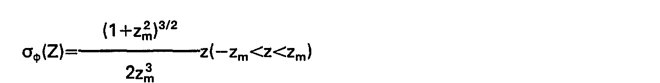
- the winding turns are further disposed so that the angular position (p on the surface of the cylindrical support structure satisfies the relationship determined by the equation where a is the radius of the coil support structure, is the normalized axial position along the axis of the coil, 110 is the permeability of free space, G z is the value of the magnetic field gradient within the interior volume of the coil in a direction parallel to the axis of the coil, I is the current flowing through the winding turns, and ⁇ ⁇ (Z) is a dimensionless shape function characterizing the number of winding turns per unit length of coil as a function of Z.
- the coil further comprises additional electrically conductive winding turns for compensating for variations in the linearity of the magnetic field gradient within the interior volume of the coil which are due to the coil being of finite length.
- An improved nuclear magnetic resonance imaging system utilizes a cylindrical coil in accordance with the instant invention to provide a magnetic field linearly graded in the direction of the central axis of the system.
- the imaging systsem further includes a means for providing a uniform high strength magnetic field along the same central axis, a means for providing linearly graded magnetic fields along two axes substantially orthogonal to the central axis and at a non-zero angle to each other, a means for generating and transmitting radio frequency signals having the required modulation to excite nuclear resonance in the sample being imaged, a means for receiving and processing the resulting NMR signals, and a means for generating images from the processed signals.
- each Cartesian component of the magnetic flux density B, and of the magnetic vector potential A satisfies the Laplace equation. Therefore, each of the Cartesian components can be written as a superposition of solid spherical harmonic functions. Equations have been developed that permit the X, Y, or Z differentiation of any solid spherical harmonic function to produce an expression consisting of solid spherical harmonics of lower order. These equations are presented in Table I. The notation for the spherical harmonics is taken from the textbook of W. D. MacMillan, The Theory of the Potential, Dover, New York, 1958. From an article by J. F. Schenck and M. A.
- a boundary condition is used. The internal vector potential is matched to an external vector potential such that each component of the magnetic vector potential is continuous across the cylindrical surface. The surface current density can be written as where the dimensions of ⁇ are amperes per meter. Using the boundary condition above, or, in vector form (at the cylindrical surface).
- the field produced by these field lines can be conveniently represented by an expression in solid spherical harmonic functions about the center of the coil system as Thus, the field produced is of the form
- a 01 is equal to a constant and A 03 , A 05 , A 07 , etc., all equal zero.
- the expansion coefficients A on are given by Therefore, when integrating the function from zero to infinity, a non-zero value for A 01 should be obtained, but a value of zero should be obtained for all higher terms.
- Equation 16 and 17 The current density given by Equations 16 and 17 is for a continuous distribution of current on the surface of the cylinder.
- the desired current density can be closely approximated by spirally winding a continuous wire around the outside surface of the cylinder.
- the best location for a discrete wire approximation to the desired continuous current density is to place the wires along the streamlines of the continuous distribution.
- the location of the wires is then the spiral path determined by integrating the differential equation Substituting Equations 16 and 17 into Equation 24, With Equation 23 rewritten as and combining Equation 26 with Equation 25, the result is obtained that With the normalization given by Equation 22, the shape function ⁇ ⁇ (Z) is With the shape function given by Equation 28, the magnetic field gradient is progressively more linear as the coil length is increased. In the limit, as Z m goes to infinity, the field gradient becomes perfectly linear.
- the coil In practice, the coil must be terminated. Many methods exist for terminating the coil in order to preserve the linearity of the field as much as possible. For Z m >1 the non-linearity in the magnetic field is due mostly to the A 03 term. Thus, the linearity can be greatly improved by superimposing on the linear winding density a coil a discrete winding located so as to cancel that term. If this discrete coil is located at Z>1 it will have relatively little effect on the higher order terms A 05 , A 07 , etc. They will remain near the low value produced by the linear coil. To analyze the properties of an elementary circular coil, z is used for the field coordinate and Z o is used as the source coordinate. Variables denoted by capital letters are again used for the normalized variables.
- Equation 32 represents the desired gradient field and all of the higher order terms are undesirable contaminants.
- the current density of the linear winding density coil can be expressed as where the constant a has the dimensions of amperes per meter.
- the coil is assumed to extend from -Z m to Z m along the z-axis.
- a strip of width ⁇ z will cary a current given by It is useful to define an effective ampere-turn count for the coil by the formula
- the field of the linear winding density coil can be found by using Z o as a weighting factor and integrating Equation 29, so that The result is which can be expanded as
- the magnetic field gradient can be found by differentiating Equation 41, so that which can be expanded as
- the value of the gradient at the origin is It is again seen that, if Z m were permitted to become very large, all of the terms in Equations 43 and 44 except for the first would go to zero, and the field gradient would be a constant.
- the coil inductance L is an important parameter, and it can be expressed as where the modulus k is defined by and where the functions K and E are the complete elliptic integrals of the first and second kind, referred to at pages 291 and 335 of the aforementioned reference Static and Dynamic Electricity.
- the inductance of the current sheet that comprises the linear gradient magnetic field coil can be calculated directly. However, doing so involves the double integration of elliptic functions, and the result is not especially useful.
- the inductance can also be calculated accurately by a less cumbersome method using a summation over loops of wire whose spacing is adjusted to correspond to the ideal current density of the coil.
- the spacing of discrete loops which corresponds to a surface current density proportional to z can be expressed as The inductance of such an array of discrete loops can be calculated as a double sum in the form In Equation 53 L o is the self inductance of an individual turn and M ⁇ is the mutual inductance of turns i and j. Taking the radius of the wire from which the loop is wound to be a o The plus sign for M ij is to be used if the two loops are on the same side of the origin; otherwise, the minus sign is to be used.
- winding turns 104 are wound on the outer surface of cylindrical coil support structure 102 so that the axial density of winding turns 104 is at a minimum at the center of the length of coil support structure 102 and increases linearly from the center to each axial end of the coil.
- Winding turns 104 are wound so that they are symmetrically located about the center of coil support structure 102.
- winding turns 104 may be wound on support structure 102 by spirally winding wire from one axial end of support structure 102 to the other axial end thereof. The wire is wound so that the density of the winding turns decreases from each axial end of support structure 102 to the center of the length thereof.
- Winding turns 104 are electrically insulated from each other in order to provide the desired current paths around the outer surface of cylindrical coil support structure 102.
- Terminal connection means 108 are used to connect wire winding turns 104 with a power supply (not shown in Figure 1).
- Winding turns 104 may be made from any electrically conductive material, such as, for example, copper.
- Coil support structure 102 may be made from any material having sufficient strength and rigidity to be formed into a cylinder of the size required for a particular application.
- support structure 102 may comprise glass fiber material.
- winding turns 104 are further disposed so that the angular position ⁇ of the spiral path of winding turns 104 on the surface of cylindrical support structure 102 satisfies the relationship determined by the equation - where a is the outer radius of coil support structure 102, is the normalized axial position along the axis of coil support structure 102, p o is the permeability of free space, G z is the value of the magnetic field gradient within the interior volume of coil support structure 102 in a direction parallel to the axis of the coil, I us the current flowing through winding turns 104, and ⁇ ⁇ (Z) is a dimensionless shape function characterizing the number of winding turns 104 per unit length of coil support structure 102 as a function of the normalized position along the length of coil support structure 102.
- the coil illustrated by Figure 1 provides a magnetic field having a substantially linear gradient in a direction parallel to the axis of coil support structure 102 when where Z m is half the length of coil support structure 102 divided by its radius.
- a particularly useful coil may be made when G z is about 0.01 Tesla per meter, I is about 30 amperes, a is about 0.327 meters and Z m is about 2, such that the coil is characterized by equal to about 356 ⁇ ⁇ (Z), ⁇ ⁇ (Z) equal to about 0.72, ⁇ equal to about 124 Z 2 , and Z equal to about 0.09 ⁇ , and such that a total of about 160 of winding turns 104 are disposed symmetrically about the center of cylindrical support structure 102, with about 80 each of winding turns 104 located between the center of the length of coil support structure 102 and each axial end thereof.
- Figure 2 illustrates a coil having additional electrically conductive winding turns for compensating for variations in the linearity of the magnetic field gradient due to the finite length of the coil.
- the coil is essentially the same as the coil shown in Figure 1, with the addition of compensating winding turns 202 and 204.
- Compensating winding turns 202 and 204 are spirally wound around the outer surface of coil support structure 102 such that the winding turn density of compensating winding turns 202 and 204 is constant for the portion of the length of coil support structure 102 where compensating winding turns are located.
- compensating winding turns 202 and 204 are wound in opposite directions around coil support structure 102, so that compensating winding turns 202 and 204 are each wound in the same direction as winding turns 104.
- compensating winding turns 202 and 204 may be wound in other directions as long as the current flowing through compensating winding turns 202 is oppositely directed from the current flowing through compensating winding turns 204.
- compensating winding turns 202 and 204 are each wound around coil support structure 102 before winding turns 104 are wound.
- compensating winding turns 202 and 204 may also be wound after winding turns 104 are wound.
- Compensating winding turns 202 are electrically insulated from each other and from compensating winding turns 204 and winding turns 104.
- Compensating winding turns 202 and 204 may be made from any electrically conductive material, such-as, for example, copper.
- Compensating terminal connection means 206 connect compensating winding turns 202 to a power supply (not shown in Figure 2).
- compensating terminal connection means 208 connect compensating winding turns 204 to a separate power supply (also not shown).
- the preferred method of including compensating winding turns in the coil is illustrated by Figure 3.
- the compensating winding turns are integrally incorporated with winding turns 104, so that current flows from one axial end of coil support structure 102 to the other by passing through both the winding turns and the compensating winding turns.
- the winding turns and the compensating winding turns are both spirally wound from the same wire, by winding the wire from one axial end of support structure 102 to the other axial end thereof.
- the winding turn density of winding turns 104 in Figure 3 decreases from each axial end of support structure 102 to the center thereof, where the direction of winding is reversed.
- the winding turn density is increased in order to provide a compensating B z field similar to that provided by separate compensating winding turns 202 and 204 shown in Figure 2.
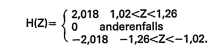
- the compensating winding turns are further disposed so that the angular position ⁇ of the spiral path of the windings on the surface of coil support structure 102 satisfies the relationship determined by Equation 55 above, where the winding turn density is described by the shape function and where
- one especially useful coil may be made when G z is about 0.01 Tesla per meter, I is about 30 amperes, a is about 0.327 meters, and Z m is about 1.5, such that the coil is characterized by equal to about 181Z+356H(Z), and by ⁇ equal to about 90Z 2 for IZI ⁇ 1.02, about 90Z 2 +719Z-733 for 1.02 ⁇
- ⁇ 1.26, and about 90Z 2 +173 for 1.26 ⁇ IZI ⁇ 1.50, and such that the coil has a total of about 120 winding turns disposed symmetrically about the center of the coil, with about 15 winding turns located on each side of Z 0 between the points along the length of the coil which correspond to Z
- the electrically conductive windings comprise a uniform diameter wire having a diameter between about and where w a is a shape-dependent coil parameter proportional to the gradient strength, defined as and where N t is the total number of winding turns and ⁇ ⁇ max is the largest value of ⁇ ⁇ (Z) in the range -Z, ⁇ Z ⁇ Zm. If the wire diameter is too large it is preferable to wind the coil in multiple layers. If the wire diameter is too small, the inductance is increased above that calculated when it is assumed that the surface current density varies smoothly with position. Also, if the total number of turns N t is too small, then the smaller variations in ⁇ ⁇ (Z) are not faithfully approximated.
- N t the total number of turns N t . If n. is the number of turns per unit length, then Using Equation 16 To accurately represent some feature of ⁇ ⁇ (Z) that has a width I and an average value ⁇ ⁇ >, the number of turns should be chosen such that For a particular value of N t , a single layer winding can be produced and the expected inductance achieved if the wire diameter d is
- the coils embodied by the present invention have reduced electrical inductance as compared to the inductance of a discrete pair of coils such as the Maxwell pair, because the total inductance of a distributed coil of the type employed in the instant invention is less than that of a discrete pair of coils.
- the coils embodied by the present invention may also include a protective material which covers the winding turns and the surface of the cylindrical coil support structure.
- protective coating 110 typically covers winding turns 104 which are wound around coil support structure 102.
- Protective material 110 may be made from any material suitable to meet the requirements of a particular application, and may comprise, for example, epoxy.
- FIG. 5 illustrates one embodiment of the manner in which the coils of the present invention may be used in a magnetic field generating system for nuclear magnetic resonance imaging.
- Cylindrical structure 302 represents a means for providing a uniform high strength magnetic field along the central axis of the system.
- structure 302 may comprise a superconducting magnet.
- coil structure 306 Inside of cylindrical structure 302, and separated therefrom by gap 304, is coil structure 306.
- Coil structure 306 contains one of the coils embodied by the present invention as a means for providing a linearly graded magnetic field in the direction of the central axis of the magnetic field generating system.
- Coil structure 306 also includes means for providing linearly graded magnetic fields along two axes which are substantially orthogonal to the central axis and which are at a non-zero angle relative to each other.
- the means employed to provide these two orthogonal fields typically comprise saddle coils of the type shown and described in the technical report by P. A. Bottomley, "Instrumentation for Whole-Body NMG Imaging", General Electric Report No. 82 CRD 203, 1982.
- FIG. 6 is a simplified block diagram showing the major components of an NMR imaging apparatus suitable for use with the magnetic field gradient coils of the present invention.
- the overall data handling system generally designated 400, comprises general purpose computer 401 which is functionally coupled to disc storage unit 403, and interface unit 405.
- RF transmitter 402, signal averager 404, and gradient power supplies 406, 408, and 410 are coupled to computer 401 through interface unit 405.
- the three gradient power supplies are used for energizing, respectively, a set of X, Y, and Z gradient coils 416, 418 and 420.
- RF transmitter 402 is gated with pulse envelopes from computer 401 to generate RF pulses having the required modulation to excite resonance in the sample being studied (imaged or spectroscopically analyzed).
- the RF pulses are amplified in RF power amplifier 412 to levels varying from 100 watts to several kilowatts, depending on the imaging method, and are applied to transmitter coil 424. Relatively high power levels are necessary for large sample volumes such as are encountered in whole body imaging, and where short duration pulses are required to excite large NMR frequency bandwidths.
- the resulting NMR signal is sensed by receiver coil 426, amplified in low noise preamplifier 422, and thereafter routed to receiver 414 for further amplification, detection, and filtering.
- This NMR signal may then be digitized and averaged by signal averager 404, and routed to computer 401 for further processing.
- the processed signals are routed from computer 401 through interface 405 to display control unit 430 where they are stored, reformatted and applied to display unit 432.
- the display unit 432 may comprise CRT displays of the direct viewing storage tube (DVST) types, as well as conventional black and white or color television-like cathode ray tubes, which may include directly viewable calibration, traces and the like.
- DVD direct viewing storage tube
- Preamplifier 422 and receiver 414 are protected from the RF pulses during transmission by active disabling gating and/or by passive filtering.
- Computer 401 provides gating and envelope modulation for the NMR pulses, blanking for the preamplifier and RF power amplifier, and voltage waveforms for the gradient power supplies.
- Computer 401 also performs data processing such as Fourier transforms, image reconstruction, data filtering, image display, and storage functions, most of which are well known and do not form an intrinsic part of the present invention.
- Transmitter and receiver RF coils may be configured as a single coil. Alternatively, two separate coils that are electrically orthogonal may be used. The latter configuration has the advantage of reduced RF pulse breakthrough into the receiver during the pulse transmission. In both cases, the coils are orthogonal to the direction of the static magnetic field B o produced by magnet 428. The coils are isolated from the remainder of the system by enclosure in an RF shielded cage (not shown). Three typical RF coil designs are illustrated as Figures 11 a, 11b, and 11C in co-pending U.S. Patent Application Serial No. 345,444, filed February 3, 1982, which is assigned to the instant assignee.
- All of the coils depicted therein produce RF magnetic fields in the x direction, and the coil designs illustrated in Figures 11b and 11c are suitable for magnetic geometries for which the axis of the sample chamber is parallel to the main field B o .
- the coil design illustrated in Figure 11 a is applicable to geometries for which the sample chamber axis is perpendicular to main field B o .
- Magnetic field gradient coils 416,418 and 420 are necessary to provide the G,,, Gy and G z gradient fields rspectively. As discussed above, the gradient fields should be monotonic and linear over the sample volume. Nonmonotonic gradient fields can cause a degradation in the NMR signal data, known as aliasing, which can lead to image artifacts. Nonlinear gradients can cause geometric distortions of the image. Coils . embodied by the instant invention are employed to produce the G z gradient field.
- the gradient G x is produced by a set of coils such as the sets 300 and 302 depicted in Figure 12a of the aforementioned application Serial No. 345,444.
- the coil sets for producing gradient Gy are rotated 90 degrees around the cylindrical axis of the sample chamber relative to the coil that produces the gradient G x .
- the foregoing describes a cylindrical coil for providing a magnetic field having a substantially linear gradient in an axial direction within the volume of the cylinder.
- the coil described uses distributed windings and has low electrical inductance.
- the present invention provides a cylindrical magnetic field gradient coil especially suitable for use with NMR apparatus.
Claims (13)


Applications Claiming Priority (2)
| Application Number | Priority Date | Filing Date | Title |
|---|---|---|---|
| US529431 | 1983-09-06 | ||
| US06/529,431 US4617516A (en) | 1983-09-06 | 1983-09-06 | Axial magnetic field gradient coil suitable for use with NMR apparatus |
Publications (3)
| Publication Number | Publication Date |
|---|---|
| EP0136536A2 EP0136536A2 (de) | 1985-04-10 |
| EP0136536A3 EP0136536A3 (en) | 1986-04-23 |
| EP0136536B1 true EP0136536B1 (de) | 1989-05-31 |
Family
ID=24109884
Family Applications (1)
| Application Number | Title | Priority Date | Filing Date |
|---|---|---|---|
| EP84110256A Expired EP0136536B1 (de) | 1983-09-06 | 1984-08-29 | Axiale Magnetfeld-Gradientenspule zur Anwendung in einem magnetischen Kernresonanzapparat |
Country Status (7)
| Country | Link |
|---|---|
| US (1) | US4617516A (de) |
| EP (1) | EP0136536B1 (de) |
| JP (1) | JPS6094705A (de) |
| KR (1) | KR880001362B1 (de) |
| DE (1) | DE3478504D1 (de) |
| FI (1) | FI88078C (de) |
| IL (1) | IL72723A (de) |
Cited By (1)
| Publication number | Priority date | Publication date | Assignee | Title |
|---|---|---|---|---|
| CZ302564B6 (cs) * | 2010-05-18 | 2011-07-13 | Ceské vysoké ucení technické v Praze - fakulta | Zapojení feromagnetické sondy pro merení gradientu magnetického pole |
Families Citing this family (51)
| Publication number | Priority date | Publication date | Assignee | Title |
|---|---|---|---|---|
| USRE36782E (en) * | 1983-11-11 | 2000-07-18 | Oxford Medical Limited | Magnet assembly for use in NMR apparatus |
| ATE132350T1 (de) | 1985-03-19 | 1996-01-15 | Randell L Mills | Verfahren und system zur erzielung einer lokalen mössbauer-absorption in einem organischen medium |
| US4689563A (en) * | 1985-06-10 | 1987-08-25 | General Electric Company | High-field nuclear magnetic resonance imaging/spectroscopy system |
| DE3585534D1 (de) * | 1985-07-25 | 1992-04-09 | Gen Electric | Supraleitende spulen zur magnetfeldkorrektur fuer hohe homogenitaet. |
| US4737716A (en) * | 1986-02-06 | 1988-04-12 | General Electric Company | Self-shielded gradient coils for nuclear magnetic resonance imaging |
| GB8615854D0 (en) * | 1986-06-28 | 1986-08-06 | Turner R | Magnetic field coils |
| FR2621125B1 (fr) * | 1987-09-28 | 1989-12-08 | Thomson Cgr | Systeme de bobines de gradient pour machine de rmn |
| FR2622303B1 (fr) * | 1987-10-27 | 1990-03-02 | Schlumberger Prospection | Procede et dispositif pour la detection de vibrations acoustiques dans un puits |
| US4794338A (en) * | 1987-11-25 | 1988-12-27 | General Electric Company | Balanced self-shielded gradient coils |
| US5289151A (en) * | 1987-12-11 | 1994-02-22 | British Technology Group Limited | Electrical coils |
| GB8729037D0 (en) * | 1987-12-11 | 1988-01-27 | Turner R | Improvements in/relating to electrical coils |
| US4949043A (en) * | 1988-04-18 | 1990-08-14 | Resonance Research Inc. | Apparatus for rendering a static magnetic field uniform |
| GB2221995B (en) * | 1988-08-19 | 1992-12-09 | Picker Int Ltd | Magnetic resonance methods and apparatus |
| US5036282A (en) * | 1989-06-16 | 1991-07-30 | Picker International, Inc. | Biplanar gradient coil for magnetic resonance imaging systems |
| US5177441A (en) * | 1989-06-16 | 1993-01-05 | Picker International, Inc. | Elliptical cross section gradient oil |
| DE4029477C2 (de) * | 1989-09-29 | 1994-06-01 | Siemens Ag | Tesserale Gradientenspule für Kernspin-Tomographiegeräte |
| JPH04332530A (ja) * | 1991-05-09 | 1992-11-19 | Toshiba Corp | Mri用傾斜磁場発生装置 |
| DE4210217C2 (de) * | 1992-03-28 | 1994-03-24 | Bruker Analytische Messtechnik | Verfahren zum Bau einer optimierten Magnetspulenanordnung |
| US5365173A (en) * | 1992-07-24 | 1994-11-15 | Picker International, Inc. | Technique for driving quadrature dual frequency RF resonators for magnetic resonance spectroscopy/imaging by four-inductive loop over coupling |
| US5289129A (en) * | 1992-10-13 | 1994-02-22 | The Trustees Of The University Of Pennsylvania | Multiple winding MRI gradient coil |
| US5357958A (en) * | 1993-03-18 | 1994-10-25 | The Regents Of The University Of California | Interventional MRI system and RF coils therefore |
| US5545996A (en) * | 1994-03-15 | 1996-08-13 | Picker International, Inc. | Gradient coil with cancelled net thrust force |
| US5581185A (en) * | 1994-03-15 | 1996-12-03 | Picker International, Inc. | Torque-balanced gradient coils for magnetic resonance imaging |
| US5485087A (en) * | 1994-08-05 | 1996-01-16 | Picker International, Inc. | Magnetic resonance insert gradient coils with parabolic returns for improved access |
| US5655533A (en) * | 1994-06-30 | 1997-08-12 | Picker International, Inc. | Actively shielded orthogonal gradient coils for wrist imaging |
| GB9801622D0 (en) * | 1998-01-23 | 1998-03-25 | Inst Of Food Research | Improvements in and relating to magnetic resonance imaging |
| IL126210A (en) * | 1998-07-01 | 2002-12-01 | Israel Aircraft Ind Ltd | Lightweight and low-excitation magnetoturker |
| KR20010095775A (ko) * | 2000-04-12 | 2001-11-07 | 장용호 | 높은 라디오주파수 자기장 균일도를 갖는 핵자기 공명또는 핵자기 영상 코일 |
| US6456076B1 (en) | 2001-01-31 | 2002-09-24 | The Trustees Of The University Of Pennsylvania | Z gradient shielding coil for canceling eddy currents |
| US6538443B2 (en) | 2001-03-20 | 2003-03-25 | Koninklijke Philips Electronics N.V. | MRI gradient coil with variable field of view and apparatus and methods employing the same |
| DE10151667C2 (de) * | 2001-10-19 | 2003-10-16 | Siemens Ag | Verfahren zur Berechnung eines schaltbaren Gradientensystems für ein Magnet-Resonanz-Tomographiegerät |
| US6885194B2 (en) | 2002-05-03 | 2005-04-26 | Ge Medical Systems Global Technology Company, Llc | Method and apparatus for minimizing gradient coil and rf coil coupling |
| CN1307663C (zh) * | 2003-05-14 | 2007-03-28 | 达方电子股份有限公司 | 变压器结构 |
| US7230426B2 (en) * | 2003-06-20 | 2007-06-12 | General Electric Company | Split-shield gradient coil with improved fringe-field |
| US7141974B2 (en) * | 2003-08-25 | 2006-11-28 | William A Edelstein | Active-passive electromagnetic shielding to reduce MRI acoustic noise |
| JP4632363B2 (ja) * | 2005-12-28 | 2011-02-16 | Necトーキン株式会社 | 磁界発生コイル |
| US7375526B2 (en) * | 2006-10-20 | 2008-05-20 | Edelstein William A | Active-passive electromagnetic shielding to reduce MRI acoustic noise |
| JP5295799B2 (ja) * | 2008-01-30 | 2013-09-18 | 株式会社東芝 | 傾斜磁場コイル、磁気共鳴イメージング装置、及び傾斜磁場コイルの製造方法 |
| JP4551946B2 (ja) * | 2008-04-21 | 2010-09-29 | 株式会社東芝 | Mri傾斜磁場発生用コイル |
| US8487729B2 (en) * | 2009-02-02 | 2013-07-16 | Northrop Grumman Guidance & Electronics | Magnetic solenoid for generating a substantially uniform magnetic field |
| US8970217B1 (en) | 2010-04-14 | 2015-03-03 | Hypres, Inc. | System and method for noise reduction in magnetic resonance imaging |
| US8698497B2 (en) * | 2010-09-23 | 2014-04-15 | General Electric Company | Multi-field-of-view gradient coil |
| FR2978834B1 (fr) | 2011-08-01 | 2014-05-16 | Commissariat Energie Atomique | Procede et systeme de generation de gradients de champ magnetique pour machine d'imagerie a rmn |
| BR112015015426A2 (pt) * | 2013-03-01 | 2017-07-11 | Halliburton Energy Services Inc | analisador de amostra de ressonância magnética nuclear (nmr) |
| US20160005530A1 (en) * | 2014-07-02 | 2016-01-07 | Analog Devices Global | Inductive component for use in an integrated circuit, a transformer and an inductor formed as part of an integrated circuit |
| US10295630B2 (en) * | 2015-08-28 | 2019-05-21 | General Electric Company | Gradient coil with variable dimension |
| EP3397978A1 (de) | 2015-12-31 | 2018-11-07 | Koninklijke Philips N.V. | Magnetfeldgradientenspulen mit dicht gepackten wicklungen und verfahren zur herstellung davon |
| DE102018113765B4 (de) | 2017-06-09 | 2023-11-02 | Analog Devices International Unlimited Company | Transformator mit einer durchkontaktierung für einen magnetkern |
| IL309321A (en) | 2017-12-01 | 2024-02-01 | Deka Products Lp | System and method for bioreactor fluid characterization using a magnetic resonance device |
| EP4105671A1 (de) * | 2021-06-16 | 2022-12-21 | Siemens Healthcare GmbH | Verfahren zur ermittlung eines magnetfeldes zumindest einer magnetspuleneinheit einer magnetresonanzvorrichtung, magnetresonanzvorrichtung und computerprogrammprodukt |
| CN116794586B (zh) * | 2023-08-02 | 2023-11-21 | 宁波健信超导科技股份有限公司 | 一种梯度线圈线性度的测量方法及测量系统 |
Family Cites Families (12)
| Publication number | Priority date | Publication date | Assignee | Title |
|---|---|---|---|---|
| DE322499C (de) * | 1918-12-15 | 1920-07-02 | Drahtlose Telegraphie M B H Ge | Unterteilte Selbstinduktionsspule fuer die Zwecke der drahtlosen Telegraphie |
| US2929017A (en) * | 1956-10-09 | 1960-03-15 | John W Seaton | Quadripole magnetic amplifier |
| US3113280A (en) * | 1960-02-01 | 1963-12-03 | Hobley Peter | Electro-magnetic means for measuring a mechanical excursion |
| US4157495A (en) * | 1976-08-14 | 1979-06-05 | Litton Systems, Inc. | Nuclear magnetic resonance gyro |
| GB1596160A (en) * | 1976-12-15 | 1981-08-19 | Nat Res Dev | Nuclear magnetic resonance apparatus and methods |
| US4319190A (en) * | 1980-03-06 | 1982-03-09 | Bell Telephone Laboratories, Incorporated | Nuclear magnetic resonance imaging in space and frequency coordinates |
| DE3131946A1 (de) * | 1981-08-12 | 1983-03-17 | Siemens AG, 1000 Berlin und 8000 München | "hochfrequenz-magnetsystem in einer einrichtung der kernspinresonanz-technik" |
| DE3133933A1 (de) * | 1981-08-27 | 1983-03-17 | Siemens AG, 1000 Berlin und 8000 München | "gradientenspulen-system einer einrichtung der kernspinresonanz-technik" |
| DE3133873A1 (de) * | 1981-08-27 | 1983-03-17 | Siemens AG, 1000 Berlin und 8000 München | Gradientenspulen-system fuer eine einrichtung der kernspinresonanz-technik |
| US4456881A (en) * | 1982-01-18 | 1984-06-26 | Technicare Corporation | Gradient-coil apparatus for a magnetic resonance system |
| US4480228A (en) * | 1982-10-15 | 1984-10-30 | General Electric Company | Selective volume method for performing localized NMR spectroscopy |
| GB8321236D0 (en) * | 1983-08-05 | 1983-09-07 | Technicare Corp | Gradient null displacement coil |
-
1983
- 1983-09-06 US US06/529,431 patent/US4617516A/en not_active Expired - Lifetime
-
1984
- 1984-08-03 FI FI843065A patent/FI88078C/fi not_active IP Right Cessation
- 1984-08-20 IL IL72723A patent/IL72723A/xx not_active IP Right Cessation
- 1984-08-29 EP EP84110256A patent/EP0136536B1/de not_active Expired
- 1984-08-29 DE DE8484110256T patent/DE3478504D1/de not_active Expired
- 1984-09-06 JP JP59185487A patent/JPS6094705A/ja active Granted
- 1984-09-06 KR KR1019840005459A patent/KR880001362B1/ko not_active IP Right Cessation
Cited By (1)
| Publication number | Priority date | Publication date | Assignee | Title |
|---|---|---|---|---|
| CZ302564B6 (cs) * | 2010-05-18 | 2011-07-13 | Ceské vysoké ucení technické v Praze - fakulta | Zapojení feromagnetické sondy pro merení gradientu magnetického pole |
Also Published As
| Publication number | Publication date |
|---|---|
| KR880001362B1 (ko) | 1988-07-28 |
| FI88078B (fi) | 1992-12-15 |
| EP0136536A3 (en) | 1986-04-23 |
| FI843065A0 (fi) | 1984-08-03 |
| IL72723A (en) | 1988-12-30 |
| FI843065A (fi) | 1985-03-07 |
| IL72723A0 (en) | 1984-11-30 |
| US4617516A (en) | 1986-10-14 |
| JPH0320056B2 (de) | 1991-03-18 |
| EP0136536A2 (de) | 1985-04-10 |
| FI88078C (fi) | 1993-03-25 |
| DE3478504D1 (en) | 1989-07-06 |
| KR850002324A (ko) | 1985-05-10 |
| JPS6094705A (ja) | 1985-05-27 |
Similar Documents
| Publication | Publication Date | Title |
|---|---|---|
| EP0136536B1 (de) | Axiale Magnetfeld-Gradientenspule zur Anwendung in einem magnetischen Kernresonanzapparat | |
| US4737716A (en) | Self-shielded gradient coils for nuclear magnetic resonance imaging | |
| US5378989A (en) | Open gradient coils for magnetic resonance imaging | |
| US4456881A (en) | Gradient-coil apparatus for a magnetic resonance system | |
| CA1253916A (en) | Nuclear magnetic resonance apparatus | |
| EP0601101B1 (de) | Methode zum Entwurf einer magnetisch abgeschirmten elektromagnetischen Spulenanordnung | |
| US5177442A (en) | Transverse gradient coils for imaging the head | |
| JP3682627B2 (ja) | 磁気共鳴撮像装置 | |
| US6342787B1 (en) | Real-time multi-axis gradient distortion correction using an interactive shim set | |
| US6078177A (en) | Flared gradient coil set with a finite shield current | |
| EP0177855B1 (de) | Hochfrequenzfeldspulenanordnung für die magnetische Kernresonanz | |
| US5655533A (en) | Actively shielded orthogonal gradient coils for wrist imaging | |
| EP0695950A2 (de) | Anordnungen von Gradientenspulen für Gerät zur Bilderzeugung durch magnetische Resonanz | |
| JPS6145959A (ja) | 磁気共鳴装置 | |
| EP0154996B1 (de) | Vorrichtung mit Trimmspulen-Korrektur zur Bilderzeugung mittels magnetischer Resonanz | |
| US6084497A (en) | Superconducting magnets | |
| US6100692A (en) | Gradient coil set with a finite shield current | |
| EP0210289B1 (de) | Supraleitende Spulen zur Magnetfeldkorrektur für hohe Homogenität | |
| US5128643A (en) | Method and apparatus for producing a region of low magnetic field | |
| Hillenbrand et al. | High-order MR shimming: a simulation study of the effectiveness of competing methods, using an established susceptibility model of the human head | |
| Zevenhoven | Solving transient problems in ultra-low-field MRI | |
| Ogle et al. | Design optimization method for a ferromagnetically self-shield MR magnet | |
| US4873503A (en) | Electrical coils | |
| US6593742B1 (en) | Biplanar homogeneous field electromagnets and method for making same | |
| AU773894B2 (en) | Asymmetric superconducting magnets for magnetic resonance imaging |
Legal Events
| Date | Code | Title | Description |
|---|---|---|---|
| PUAI | Public reference made under article 153(3) epc to a published international application that has entered the european phase |
Free format text: ORIGINAL CODE: 0009012 |
|
| AK | Designated contracting states |
Designated state(s): CH DE FR GB IT LI NL SE |
|
| PUAL | Search report despatched |
Free format text: ORIGINAL CODE: 0009013 |
|
| AK | Designated contracting states |
Kind code of ref document: A3 Designated state(s): CH DE FR GB IT LI NL SE |
|
| 17P | Request for examination filed |
Effective date: 19861002 |
|
| 17Q | First examination report despatched |
Effective date: 19880706 |
|
| GRAA | (expected) grant |
Free format text: ORIGINAL CODE: 0009210 |
|
| AK | Designated contracting states |
Kind code of ref document: B1 Designated state(s): CH DE FR GB IT LI NL SE |
|
| REF | Corresponds to: |
Ref document number: 3478504 Country of ref document: DE Date of ref document: 19890706 |
|
| ET | Fr: translation filed | ||
| ITF | It: translation for a ep patent filed |
Owner name: SAIC BREVETTI S.R.L. |
|
| PLBE | No opposition filed within time limit |
Free format text: ORIGINAL CODE: 0009261 |
|
| STAA | Information on the status of an ep patent application or granted ep patent |
Free format text: STATUS: NO OPPOSITION FILED WITHIN TIME LIMIT |
|
| 26N | No opposition filed | ||
| ITTA | It: last paid annual fee | ||
| PGFP | Annual fee paid to national office [announced via postgrant information from national office to epo] |
Ref country code: FR Payment date: 19920709 Year of fee payment: 9 |
|
| PGFP | Annual fee paid to national office [announced via postgrant information from national office to epo] |
Ref country code: CH Payment date: 19920714 Year of fee payment: 9 |
|
| PGFP | Annual fee paid to national office [announced via postgrant information from national office to epo] |
Ref country code: SE Payment date: 19920716 Year of fee payment: 9 |
|
| PGFP | Annual fee paid to national office [announced via postgrant information from national office to epo] |
Ref country code: GB Payment date: 19920720 Year of fee payment: 9 |
|
| PGFP | Annual fee paid to national office [announced via postgrant information from national office to epo] |
Ref country code: NL Payment date: 19920831 Year of fee payment: 9 |
|
| REG | Reference to a national code |
Ref country code: GB Ref legal event code: 746 |
|
| REG | Reference to a national code |
Ref country code: FR Ref legal event code: DL |
|
| PG25 | Lapsed in a contracting state [announced via postgrant information from national office to epo] |
Ref country code: GB Effective date: 19930829 |
|
| PG25 | Lapsed in a contracting state [announced via postgrant information from national office to epo] |
Ref country code: SE Effective date: 19930830 |
|
| PG25 | Lapsed in a contracting state [announced via postgrant information from national office to epo] |
Ref country code: LI Effective date: 19930831 Ref country code: CH Effective date: 19930831 |
|
| PG25 | Lapsed in a contracting state [announced via postgrant information from national office to epo] |
Ref country code: NL Effective date: 19940301 |
|
| NLV4 | Nl: lapsed or anulled due to non-payment of the annual fee | ||
| GBPC | Gb: european patent ceased through non-payment of renewal fee |
Effective date: 19930829 |
|
| PG25 | Lapsed in a contracting state [announced via postgrant information from national office to epo] |
Ref country code: FR Effective date: 19940429 |
|
| REG | Reference to a national code |
Ref country code: CH Ref legal event code: PL |
|
| REG | Reference to a national code |
Ref country code: FR Ref legal event code: ST |
|
| EUG | Se: european patent has lapsed |
Ref document number: 84110256.9 Effective date: 19940310 |
|
| PGFP | Annual fee paid to national office [announced via postgrant information from national office to epo] |
Ref country code: DE Payment date: 20030930 Year of fee payment: 20 |