EP0136503A2 - Bürstenhalterungsanordnung - Google Patents
Bürstenhalterungsanordnung Download PDFInfo
- Publication number
- EP0136503A2 EP0136503A2 EP84109809A EP84109809A EP0136503A2 EP 0136503 A2 EP0136503 A2 EP 0136503A2 EP 84109809 A EP84109809 A EP 84109809A EP 84109809 A EP84109809 A EP 84109809A EP 0136503 A2 EP0136503 A2 EP 0136503A2
- Authority
- EP
- European Patent Office
- Prior art keywords
- brush
- lead wire
- draw
- retaining device
- out hole
- Prior art date
- Legal status (The legal status is an assumption and is not a legal conclusion. Google has not performed a legal analysis and makes no representation as to the accuracy of the status listed.)
- Granted
Links
Images
Classifications
-
- H—ELECTRICITY
- H01—ELECTRIC ELEMENTS
- H01R—ELECTRICALLY-CONDUCTIVE CONNECTIONS; STRUCTURAL ASSOCIATIONS OF A PLURALITY OF MUTUALLY-INSULATED ELECTRICAL CONNECTING ELEMENTS; COUPLING DEVICES; CURRENT COLLECTORS
- H01R39/00—Rotary current collectors, distributors or interrupters
- H01R39/02—Details for dynamo electric machines
- H01R39/38—Brush holders
- H01R39/40—Brush holders enabling brush movement within holder during current collection
Definitions
- the present invention relates to a brush-retaining device for a generator, a motor and so on. More particularly, it relates to an improvement in a brush holder for receiving and holding brushes in a movable manner.
- a brush which is a structural element of the brush-retaining device is made in slide-contact with a slip ring rotated along with a rotor and is received in a brush holder in a movable manner.
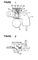
- FIGS 1 and 2 show a conventional brush-retaining device.
- a brush-retaining device 11 comprises a base plate lla and a brush holder 12 fixed to the base plate lla.
- the brush holder 12 is formed by molding a thermosetting resin, in which a cavity 12a for receiving a conducting brush 21 and a conducting lead wire 22 so that they are movable in the cavity 12a, and a draw-out hole 12b for drawing out the lead wire 12b are formed.
- the lead wire 22 has its one end connected to the brusn 21 and the other end connected to a connecting terminal 23. For allowing movement of the brush 21 in the brush holder 12, there is a gap 51 between the inner wall of the brush holder 12 and the brush 21.
- the draw-out hole 12b for the lead wire 22 is left opened, with the consequence that foreign substance such as salt water, muddy water and so on is apt to enter into the brush holder 12.
- the salt water or the muddy water easily reaches the gap 51 between the holder 12 and the brush 21, and causes the inner wall of the brush holder 12 and the outer surface of the brush 21 to be rusted and fixed to each other. Consequently, the brush 21 ceases to slide within the brush holder 12. Further, since there is no measure to make the lead wire 22 immovable other than the brush which holds one end of the lead wire 22 and the connecting terminal 23 which holds the other end, the lead wire may be broken due to resonance vibration caused by an external force.
- a brush-retaining device comprising a conducting brush being in slide-contact with a rotating conduction part, a conducting lead wire having one end connected to the conducting brush and the other end connected to a connecting terminal, a brush holder provided with a cavity for receiving the brush and the lead wire in a movable manner and a draw-out hole for lead wire and an insulating cover for covering the entire region of the draw-out hole for lead wire and at least a part of the lead wire, the insulating cover being provided with an elastically engaging part to be fitted to the draw-out hole for lead wire.
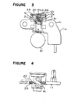
- a brush holder 12 made of synthetic resin is provided with a cavity 12a which receives a conducting brush 21 and a conducting lead wire 22 in a movable manner and a draw-out hole 12b for lead wire.
- An annular projection 12c is integrally formed in a circular inner wall of the draw-out hole 12b.
- a spring 31 extends in the cavity 12a to urge the brush 21 to a slip ring 61 which constitutes a rotating conduction part and the brush 21 is in slide-contact with it.
- the brush 21 is a sintered body of a mixture of copper and natural graphite.
- an insulating cover 41 formed by molding a insulative resinous material such as Nylon 66 comprises a flat plate portion 41a which covers the entire region of the draw-out hole 12b and at least a part of lead wires 22 and two elastically engaging parts 41b of a generally cylindrical shape which are formed integrally with the flat plate portion 41a and are repectively engaged with the annular projections 12c formed in the inner walls of the draw-out holes 12b.
- Each of the elastically engaging parts 41b is provided with four vertical slits which are respectively formed by dividing a circle at a given interval so that the elastically engaging part 41b can be easily bent inwardly.
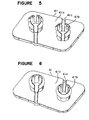
- the brush-retaininc device of the present invention may be provided with two brush holders 12 each having an elastically engaging part 41b and a groove for lead wire 41c.
- a brush 21 and a lead wire 22 connected to the brush 21 at its one end are put in the brush holder 12 from an opening at the side of the slip ring 61. Then, the other end of the lead wire 22 is drawn-out from the draw-out hole 12b to connect to the connecting terminal 23 and thereafter, the engaging part 41b of the insulating cover 41 is engaged with the annular projection 12c while the lead wire 22 is led into the groove 41c formed in the cover 41, whereby the cover 41 is secured to the brush holder 12.
- the draw-out hole 12b is completely covered by the insulating cover 41 to prevent entrance of salt water or muddy water into the brush holder 12 from the outside.
- the lead wire 22 is immovably held in the groove 41c in association with the lower surface of the insulating cover 41 and the upper surface of the brush holder 12. As a result, there is no risk of resonance vibration due to an external force, and the lead wire 22 is prevented from breaking.
- the insulating cover can be easily fitted to the brush holder 12 because the engaging part 41b is divided into four parts which are arranged at a given interval in a circle and each of the divided parts of the engaging part 41b is easily bent inwardly.
- the engaging part 41b is divided into four parts. However, it is possible to divide it into more than or less than four. Further, it is possible to form the elastically engaging part 41b to have an annular form without dividing it and a part of the annular part may be cut so as to pass the lead wire 22 as shown in Figure 6.
Landscapes
- Motor Or Generator Current Collectors (AREA)
- Motor Or Generator Frames (AREA)
Applications Claiming Priority (2)
| Application Number | Priority Date | Filing Date | Title |
|---|---|---|---|
| JP1983139367U JPS6048364U (ja) | 1983-09-06 | 1983-09-06 | ブラシホルダ |
| JP139367/83U | 1983-09-06 |
Publications (3)
| Publication Number | Publication Date |
|---|---|
| EP0136503A2 true EP0136503A2 (de) | 1985-04-10 |
| EP0136503A3 EP0136503A3 (en) | 1987-12-16 |
| EP0136503B1 EP0136503B1 (de) | 1990-10-31 |
Family
ID=15243673
Family Applications (1)
| Application Number | Title | Priority Date | Filing Date |
|---|---|---|---|
| EP84109809A Expired EP0136503B1 (de) | 1983-09-06 | 1984-08-17 | Bürstenhalterungsanordnung |
Country Status (4)
| Country | Link |
|---|---|
| US (1) | US4554476A (de) |
| EP (1) | EP0136503B1 (de) |
| JP (1) | JPS6048364U (de) |
| DE (1) | DE3483505D1 (de) |
Cited By (1)
| Publication number | Priority date | Publication date | Assignee | Title |
|---|---|---|---|---|
| US5070270A (en) * | 1987-03-04 | 1991-12-03 | Mitsubishi Denki K.K. | Brush device |
Families Citing this family (12)
| Publication number | Priority date | Publication date | Assignee | Title |
|---|---|---|---|---|
| US4744017A (en) * | 1987-08-24 | 1988-05-10 | Grady John K | High tension power supply with means for preventing transformer saturation |
| JP2599778B2 (ja) * | 1988-12-14 | 1997-04-16 | 三菱電機株式会社 | 直流機 |
| JPH0732569B2 (ja) * | 1989-08-31 | 1995-04-10 | 株式会社三ツ葉電機製作所 | 電動モータにおける刷子ホルダの構造および該刷子ホルダ製造用の金型構造 |
| US5266022A (en) * | 1989-08-31 | 1993-11-30 | Mitsuba Electric Manufacturing Co., Ltd. | Mold structure for manufacturing brush holder as part of an integrated molding process for an electric motor gear frame housing |
| US5227688A (en) * | 1990-09-27 | 1993-07-13 | Mitsubishi Denki K. K. | Brush holder for vehicular A.C. generator |
| JPH0755034B2 (ja) * | 1990-09-27 | 1995-06-07 | 三菱電機株式会社 | 車両用交流発電機のブラシ保持器 |
| JP3004809B2 (ja) * | 1992-05-25 | 2000-01-31 | アスモ株式会社 | 直流機 |
| US5231322A (en) * | 1992-08-07 | 1993-07-27 | Ford Motor Company | Cartridge brush with integral filter inductor |
| US5373210A (en) * | 1993-03-05 | 1994-12-13 | Shop Vac Corporation | Motor brush spring subassembly |
| JP3908096B2 (ja) | 2002-06-12 | 2007-04-25 | 三菱電機株式会社 | 回転電機 |
| DE102006000496A1 (de) * | 2006-09-29 | 2008-04-03 | Hilti Ag | Kohlebürste mit Verschleissschutzmitteln |
| DE102021115993A1 (de) | 2021-06-21 | 2022-12-22 | Bayerische Motoren Werke Aktiengesellschaft | Stromübertragungs-Teilvorrichtung einer stromerregten Synchronmaschine als Antriebsmotor in einem Hybrid- oder Elektrofahrzeug |
Family Cites Families (13)
| Publication number | Priority date | Publication date | Assignee | Title |
|---|---|---|---|---|
| US1457896A (en) * | 1921-08-12 | 1923-06-05 | Domestic Electric Company | Motor brush holder |
| US2852710A (en) * | 1955-07-18 | 1958-09-16 | Majik Ironers Inc | Brush holder |
| US2857540A (en) * | 1955-09-22 | 1958-10-21 | Gen Electric | Electric contact brush assembly |
| US3159763A (en) * | 1960-03-07 | 1964-12-01 | Gen Motors Corp | Brush rigging |
| BE672364A (de) * | 1964-11-17 | |||
| US3579007A (en) * | 1969-10-30 | 1971-05-18 | Sunbeam Corp | Commutator brush structure for electric motor |
| DE7025828U (de) * | 1970-07-09 | 1972-02-03 | Bosch Gmbh Robert | Buerstenhalter fuer elektrische motoren, insbesondere andrehmotoren fuer kraftfahrzeuge. |
| US3654504A (en) * | 1971-03-29 | 1972-04-04 | Gen Electric | Brush mechanism |
| JPS4815281U (de) * | 1971-06-26 | 1973-02-21 | ||
| US3735172A (en) * | 1971-12-22 | 1973-05-22 | Gen Signal Corp | Motor brush holder |
| JPS5497716A (en) * | 1978-01-20 | 1979-08-02 | Hitachi Ltd | Commutator motor |
| IT8035721U1 (it) * | 1980-05-02 | 1981-11-02 | Fabbrica Italiana Magneti Marelli S P A | Disco porta spazzole di motorini di avviamento, particolarmente per autovetture |
| JPS57110053A (en) * | 1980-12-26 | 1982-07-08 | Nippon Denso Co Ltd | Brush holder |
-
1983
- 1983-09-06 JP JP1983139367U patent/JPS6048364U/ja active Granted
-
1984
- 1984-08-17 EP EP84109809A patent/EP0136503B1/de not_active Expired
- 1984-08-17 DE DE8484109809T patent/DE3483505D1/de not_active Expired - Lifetime
- 1984-08-20 US US06/642,210 patent/US4554476A/en not_active Expired - Lifetime
Cited By (1)
| Publication number | Priority date | Publication date | Assignee | Title |
|---|---|---|---|---|
| US5070270A (en) * | 1987-03-04 | 1991-12-03 | Mitsubishi Denki K.K. | Brush device |
Also Published As
| Publication number | Publication date |
|---|---|
| DE3483505D1 (en) | 1990-12-06 |
| EP0136503A3 (en) | 1987-12-16 |
| US4554476A (en) | 1985-11-19 |
| EP0136503B1 (de) | 1990-10-31 |
| JPH0514706Y2 (de) | 1993-04-19 |
| JPS6048364U (ja) | 1985-04-05 |
Similar Documents
| Publication | Publication Date | Title |
|---|---|---|
| EP0142237B1 (de) | Komponenten elektrischer Motoren | |
| EP0136503A2 (de) | Bürstenhalterungsanordnung | |
| US4355253A (en) | Combination end bell and brush holder for a dynamoelectric machine | |
| US3745393A (en) | Brush holder for dynamoelectric machine | |
| EP0236254B1 (de) | Bürstenhalter für dynamoelektrische Maschine | |
| US5440186A (en) | Motor with isolated brush card assembly | |
| US3967148A (en) | Brush holder assembly | |
| US4746828A (en) | Molded electric motor housing and brush holder unit | |
| US3210577A (en) | Encapsulated electric motor | |
| US4041339A (en) | Dynamoelectric machine with brush holding structure | |
| US3735172A (en) | Motor brush holder | |
| US4429243A (en) | Compartmentized lead wire terminal housing for electric motor | |
| CA2062647A1 (en) | Structure for coupling field windings to motor brushes | |
| US5736805A (en) | Brush retaining clip and electrical connection | |
| US3525891A (en) | Brush mounting arrangement for dynamoelectric machines | |
| ES2007520A6 (es) | Motor electrico con interruptor de proteccion. | |
| US3867659A (en) | Brush holder assembly | |
| US5679996A (en) | Assembled commutator | |
| US4876474A (en) | Commutator | |
| JPS6412068B2 (de) | ||
| US5563467A (en) | Electromotor brush holders using a punched grid | |
| KR100876070B1 (ko) | 전기기계의 하나 또는 다수의 기능소자를 포함하는 하우징 | |
| US4356420A (en) | Brush holder for rotating electrical machines | |
| US3187214A (en) | Brush retaining means for electric motor | |
| GB2178248A (en) | Brush holder for commutator type starter motors |
Legal Events
| Date | Code | Title | Description |
|---|---|---|---|
| PUAI | Public reference made under article 153(3) epc to a published international application that has entered the european phase |
Free format text: ORIGINAL CODE: 0009012 |
|
| AK | Designated contracting states |
Designated state(s): DE FR GB IT |
|
| PUAL | Search report despatched |
Free format text: ORIGINAL CODE: 0009013 |
|
| AK | Designated contracting states |
Kind code of ref document: A3 Designated state(s): DE FR GB IT |
|
| 17P | Request for examination filed |
Effective date: 19880114 |
|
| 17Q | First examination report despatched |
Effective date: 19890811 |
|
| GRAA | (expected) grant |
Free format text: ORIGINAL CODE: 0009210 |
|
| AK | Designated contracting states |
Kind code of ref document: B1 Designated state(s): DE FR GB IT |
|
| ITF | It: translation for a ep patent filed | ||
| REF | Corresponds to: |
Ref document number: 3483505 Country of ref document: DE Date of ref document: 19901206 |
|
| ET | Fr: translation filed | ||
| ITTA | It: last paid annual fee | ||
| PLBE | No opposition filed within time limit |
Free format text: ORIGINAL CODE: 0009261 |
|
| STAA | Information on the status of an ep patent application or granted ep patent |
Free format text: STATUS: NO OPPOSITION FILED WITHIN TIME LIMIT |
|
| 26N | No opposition filed | ||
| REG | Reference to a national code |
Ref country code: GB Ref legal event code: IF02 |
|
| PGFP | Annual fee paid to national office [announced via postgrant information from national office to epo] |
Ref country code: FR Payment date: 20030808 Year of fee payment: 20 |
|
| PGFP | Annual fee paid to national office [announced via postgrant information from national office to epo] |
Ref country code: GB Payment date: 20030813 Year of fee payment: 20 |
|
| PGFP | Annual fee paid to national office [announced via postgrant information from national office to epo] |
Ref country code: DE Payment date: 20030828 Year of fee payment: 20 |
|
| PG25 | Lapsed in a contracting state [announced via postgrant information from national office to epo] |
Ref country code: GB Free format text: LAPSE BECAUSE OF EXPIRATION OF PROTECTION Effective date: 20040816 |
|
| REG | Reference to a national code |
Ref country code: GB Ref legal event code: PE20 |