EP0136503A2 - Brush-retaining device - Google Patents
Brush-retaining device Download PDFInfo
- Publication number
- EP0136503A2 EP0136503A2 EP84109809A EP84109809A EP0136503A2 EP 0136503 A2 EP0136503 A2 EP 0136503A2 EP 84109809 A EP84109809 A EP 84109809A EP 84109809 A EP84109809 A EP 84109809A EP 0136503 A2 EP0136503 A2 EP 0136503A2
- Authority
- EP
- European Patent Office
- Prior art keywords
- brush
- lead wire
- draw
- retaining device
- out hole
- Prior art date
- Legal status (The legal status is an assumption and is not a legal conclusion. Google has not performed a legal analysis and makes no representation as to the accuracy of the status listed.)
- Granted
Links
- WABPQHHGFIMREM-UHFFFAOYSA-N lead(0) Chemical compound [Pb] WABPQHHGFIMREM-UHFFFAOYSA-N 0.000 claims abstract description 43
- 239000000126 substance Substances 0.000 abstract description 3
- XLYOFNOQVPJJNP-UHFFFAOYSA-N water Substances O XLYOFNOQVPJJNP-UHFFFAOYSA-N 0.000 description 8
- 150000003839 salts Chemical class 0.000 description 4
- 238000000465 moulding Methods 0.000 description 2
- RYGMFSIKBFXOCR-UHFFFAOYSA-N Copper Chemical compound [Cu] RYGMFSIKBFXOCR-UHFFFAOYSA-N 0.000 description 1
- 229920002302 Nylon 6,6 Polymers 0.000 description 1
- 238000010276 construction Methods 0.000 description 1
- 229910052802 copper Inorganic materials 0.000 description 1
- 239000010949 copper Substances 0.000 description 1
- JEIPFZHSYJVQDO-UHFFFAOYSA-N iron(III) oxide Inorganic materials O=[Fe]O[Fe]=O JEIPFZHSYJVQDO-UHFFFAOYSA-N 0.000 description 1
- 239000000203 mixture Substances 0.000 description 1
- 229910021382 natural graphite Inorganic materials 0.000 description 1
- 229920005989 resin Polymers 0.000 description 1
- 239000011347 resin Substances 0.000 description 1
- 239000012260 resinous material Substances 0.000 description 1
- 229920003002 synthetic resin Polymers 0.000 description 1
- 239000000057 synthetic resin Substances 0.000 description 1
- 229920001187 thermosetting polymer Polymers 0.000 description 1
Images
Classifications
-
- H—ELECTRICITY
- H01—ELECTRIC ELEMENTS
- H01R—ELECTRICALLY-CONDUCTIVE CONNECTIONS; STRUCTURAL ASSOCIATIONS OF A PLURALITY OF MUTUALLY-INSULATED ELECTRICAL CONNECTING ELEMENTS; COUPLING DEVICES; CURRENT COLLECTORS
- H01R39/00—Rotary current collectors, distributors or interrupters
- H01R39/02—Details for dynamo electric machines
- H01R39/38—Brush holders
- H01R39/40—Brush holders enabling brush movement within holder during current collection
Definitions
- the present invention relates to a brush-retaining device for a generator, a motor and so on. More particularly, it relates to an improvement in a brush holder for receiving and holding brushes in a movable manner.
- a brush which is a structural element of the brush-retaining device is made in slide-contact with a slip ring rotated along with a rotor and is received in a brush holder in a movable manner.
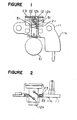
- FIGS 1 and 2 show a conventional brush-retaining device.
- a brush-retaining device 11 comprises a base plate lla and a brush holder 12 fixed to the base plate lla.
- the brush holder 12 is formed by molding a thermosetting resin, in which a cavity 12a for receiving a conducting brush 21 and a conducting lead wire 22 so that they are movable in the cavity 12a, and a draw-out hole 12b for drawing out the lead wire 12b are formed.
- the lead wire 22 has its one end connected to the brusn 21 and the other end connected to a connecting terminal 23. For allowing movement of the brush 21 in the brush holder 12, there is a gap 51 between the inner wall of the brush holder 12 and the brush 21.
- the draw-out hole 12b for the lead wire 22 is left opened, with the consequence that foreign substance such as salt water, muddy water and so on is apt to enter into the brush holder 12.
- the salt water or the muddy water easily reaches the gap 51 between the holder 12 and the brush 21, and causes the inner wall of the brush holder 12 and the outer surface of the brush 21 to be rusted and fixed to each other. Consequently, the brush 21 ceases to slide within the brush holder 12. Further, since there is no measure to make the lead wire 22 immovable other than the brush which holds one end of the lead wire 22 and the connecting terminal 23 which holds the other end, the lead wire may be broken due to resonance vibration caused by an external force.
- a brush-retaining device comprising a conducting brush being in slide-contact with a rotating conduction part, a conducting lead wire having one end connected to the conducting brush and the other end connected to a connecting terminal, a brush holder provided with a cavity for receiving the brush and the lead wire in a movable manner and a draw-out hole for lead wire and an insulating cover for covering the entire region of the draw-out hole for lead wire and at least a part of the lead wire, the insulating cover being provided with an elastically engaging part to be fitted to the draw-out hole for lead wire.
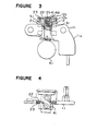
- a brush holder 12 made of synthetic resin is provided with a cavity 12a which receives a conducting brush 21 and a conducting lead wire 22 in a movable manner and a draw-out hole 12b for lead wire.
- An annular projection 12c is integrally formed in a circular inner wall of the draw-out hole 12b.
- a spring 31 extends in the cavity 12a to urge the brush 21 to a slip ring 61 which constitutes a rotating conduction part and the brush 21 is in slide-contact with it.
- the brush 21 is a sintered body of a mixture of copper and natural graphite.
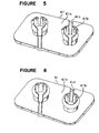
- an insulating cover 41 formed by molding a insulative resinous material such as Nylon 66 comprises a flat plate portion 41a which covers the entire region of the draw-out hole 12b and at least a part of lead wires 22 and two elastically engaging parts 41b of a generally cylindrical shape which are formed integrally with the flat plate portion 41a and are repectively engaged with the annular projections 12c formed in the inner walls of the draw-out holes 12b.
- Each of the elastically engaging parts 41b is provided with four vertical slits which are respectively formed by dividing a circle at a given interval so that the elastically engaging part 41b can be easily bent inwardly.
- the brush-retaininc device of the present invention may be provided with two brush holders 12 each having an elastically engaging part 41b and a groove for lead wire 41c.
- a brush 21 and a lead wire 22 connected to the brush 21 at its one end are put in the brush holder 12 from an opening at the side of the slip ring 61. Then, the other end of the lead wire 22 is drawn-out from the draw-out hole 12b to connect to the connecting terminal 23 and thereafter, the engaging part 41b of the insulating cover 41 is engaged with the annular projection 12c while the lead wire 22 is led into the groove 41c formed in the cover 41, whereby the cover 41 is secured to the brush holder 12.
- the draw-out hole 12b is completely covered by the insulating cover 41 to prevent entrance of salt water or muddy water into the brush holder 12 from the outside.
- the lead wire 22 is immovably held in the groove 41c in association with the lower surface of the insulating cover 41 and the upper surface of the brush holder 12. As a result, there is no risk of resonance vibration due to an external force, and the lead wire 22 is prevented from breaking.
- the insulating cover can be easily fitted to the brush holder 12 because the engaging part 41b is divided into four parts which are arranged at a given interval in a circle and each of the divided parts of the engaging part 41b is easily bent inwardly.
- the engaging part 41b is divided into four parts. However, it is possible to divide it into more than or less than four. Further, it is possible to form the elastically engaging part 41b to have an annular form without dividing it and a part of the annular part may be cut so as to pass the lead wire 22 as shown in Figure 6.
Landscapes
- Motor Or Generator Current Collectors (AREA)
- Motor Or Generator Frames (AREA)
Abstract
Description
- The present invention relates to a brush-retaining device for a generator, a motor and so on. More particularly, it relates to an improvement in a brush holder for receiving and holding brushes in a movable manner.
- Various types of brush-retaining device have been proposed to use them in rotating machines such as generators and motors. A brush which is a structural element of the brush-retaining device is made in slide-contact with a slip ring rotated along with a rotor and is received in a brush holder in a movable manner.
- Figures 1 and 2 show a conventional brush-retaining device. In Figures 1 and 2, a brush-retaining
device 11 comprises a base plate lla and abrush holder 12 fixed to the base plate lla. Thebrush holder 12 is formed by molding a thermosetting resin, in which a cavity 12a for receiving a conductingbrush 21 and a conductinglead wire 22 so that they are movable in the cavity 12a, and a draw-outhole 12b for drawing out thelead wire 12b are formed. Thelead wire 22 has its one end connected to thebrusn 21 and the other end connected to a connectingterminal 23. For allowing movement of thebrush 21 in thebrush holder 12, there is agap 51 between the inner wall of thebrush holder 12 and thebrush 21. - In the conventional brush-retaining device having the construction as above-mentioned, the draw-out
hole 12b for thelead wire 22 is left opened, with the consequence that foreign substance such as salt water, muddy water and so on is apt to enter into thebrush holder 12. The salt water or the muddy water easily reaches thegap 51 between theholder 12 and thebrush 21, and causes the inner wall of thebrush holder 12 and the outer surface of thebrush 21 to be rusted and fixed to each other. Consequently, thebrush 21 ceases to slide within thebrush holder 12. Further, since there is no measure to make thelead wire 22 immovable other than the brush which holds one end of thelead wire 22 and the connectingterminal 23 which holds the other end, the lead wire may be broken due to resonance vibration caused by an external force. - It is the main object of the present invention to provide a brush-retaining device for preventing entrance of foreign substances such as salt water, muddy water and so on as well as breakage of the lead wire.
- It is another object of the present invention to provide a brush-retaining device allowing easy assembly.
- The foregoing and the other objects of the present invention nave been attained by providing a brush-retaining device comprising a conducting brush being in slide-contact with a rotating conduction part, a conducting lead wire having one end connected to the conducting brush and the other end connected to a connecting terminal, a brush holder provided with a cavity for receiving the brush and the lead wire in a movable manner and a draw-out hole for lead wire and an insulating cover for covering the entire region of the draw-out hole for lead wire and at least a part of the lead wire, the insulating cover being provided with an elastically engaging part to be fitted to the draw-out hole for lead wire.
- The invention is described in more detail at hand of the accompanying drawings, in which
- Figure 1 is a front view partly cross-sectioned of a conventional brush-retaining device;
- Figure 2 is a plan view of the brush-retaining device shown in Figure 1;
- Figure 3 is a front view partly cross-sectioned of an embodiment of the brush-retaining device of the present invention;
- Figure 4 is a plan view of the brush-retaining device shown in Figure 3; and
- Figures 5 and 6 are respectively perspective views of embodiments of an insulating cover used for the brush-retaining device of the present invention.
- An embodiment of the present invention will be described with reference to Figures 3 - 5. In Figures 3 and 4, a
brush holder 12 made of synthetic resin is provided with a cavity 12a which receives a conductingbrush 21 and a conductinglead wire 22 in a movable manner and a draw-outhole 12b for lead wire. Anannular projection 12c is integrally formed in a circular inner wall of the draw-outhole 12b. Aspring 31 extends in the cavity 12a to urge thebrush 21 to aslip ring 61 which constitutes a rotating conduction part and thebrush 21 is in slide-contact with it. Thebrush 21 is a sintered body of a mixture of copper and natural graphite. As shown in Figure 5, an insulatingcover 41 formed by molding a insulative resinous material such as Nylon 66 comprises a flat plate portion 41a which covers the entire region of the draw-outhole 12b and at least a part oflead wires 22 and two elastically engaging parts 41b of a generally cylindrical shape which are formed integrally with the flat plate portion 41a and are repectively engaged with theannular projections 12c formed in the inner walls of the draw-outholes 12b. Each of the elastically engaging parts 41b is provided with four vertical slits which are respectively formed by dividing a circle at a given interval so that the elastically engaging part 41b can be easily bent inwardly.Grooves 41c are formed in the flat plate portion 41a to let thelead wire 22 to pass from the engaging part 41b. As snown in Figure 5, the brush-retaininc device of the present invention may be provided with twobrush holders 12 each having an elastically engaging part 41b and a groove forlead wire 41c. - In this embodiment, a
brush 21 and alead wire 22 connected to thebrush 21 at its one end are put in thebrush holder 12 from an opening at the side of theslip ring 61. Then, the other end of thelead wire 22 is drawn-out from the draw-outhole 12b to connect to the connectingterminal 23 and thereafter, the engaging part 41b of theinsulating cover 41 is engaged with theannular projection 12c while thelead wire 22 is led into thegroove 41c formed in thecover 41, whereby thecover 41 is secured to thebrush holder 12. Thus, the draw-outhole 12b is completely covered by the insulatingcover 41 to prevent entrance of salt water or muddy water into thebrush holder 12 from the outside. Accordingly, there takes place no rust on the inner wall of the brush holder and the outer surface of thebrush 21, hence difficulty of sliding movement of thebrush 21 is eliminated. Further, thelead wire 22 is immovably held in thegroove 41c in association with the lower surface of theinsulating cover 41 and the upper surface of thebrush holder 12. As a result, there is no risk of resonance vibration due to an external force, and thelead wire 22 is prevented from breaking. - In this embodiment, the insulating cover can be easily fitted to the
brush holder 12 because the engaging part 41b is divided into four parts which are arranged at a given interval in a circle and each of the divided parts of the engaging part 41b is easily bent inwardly. - In the embodiment, the engaging part 41b is divided into four parts. However, it is possible to divide it into more than or less than four. Further, it is possible to form the elastically engaging part 41b to have an annular form without dividing it and a part of the annular part may be cut so as to pass the
lead wire 22 as shown in Figure 6.
Claims (4)
Applications Claiming Priority (2)
| Application Number | Priority Date | Filing Date | Title |
|---|---|---|---|
| JP139367/83U | 1983-09-06 | ||
| JP1983139367U JPS6048364U (en) | 1983-09-06 | 1983-09-06 | brush holder |
Publications (3)
| Publication Number | Publication Date |
|---|---|
| EP0136503A2 true EP0136503A2 (en) | 1985-04-10 |
| EP0136503A3 EP0136503A3 (en) | 1987-12-16 |
| EP0136503B1 EP0136503B1 (en) | 1990-10-31 |
Family
ID=15243673
Family Applications (1)
| Application Number | Title | Priority Date | Filing Date |
|---|---|---|---|
| EP84109809A Expired EP0136503B1 (en) | 1983-09-06 | 1984-08-17 | Brush-retaining device |
Country Status (4)
| Country | Link |
|---|---|
| US (1) | US4554476A (en) |
| EP (1) | EP0136503B1 (en) |
| JP (1) | JPS6048364U (en) |
| DE (1) | DE3483505D1 (en) |
Cited By (1)
| Publication number | Priority date | Publication date | Assignee | Title |
|---|---|---|---|---|
| US5070270A (en) * | 1987-03-04 | 1991-12-03 | Mitsubishi Denki K.K. | Brush device |
Families Citing this family (12)
| Publication number | Priority date | Publication date | Assignee | Title |
|---|---|---|---|---|
| US4744017A (en) * | 1987-08-24 | 1988-05-10 | Grady John K | High tension power supply with means for preventing transformer saturation |
| JP2599778B2 (en) * | 1988-12-14 | 1997-04-16 | 三菱電機株式会社 | DC machine |
| US5266022A (en) * | 1989-08-31 | 1993-11-30 | Mitsuba Electric Manufacturing Co., Ltd. | Mold structure for manufacturing brush holder as part of an integrated molding process for an electric motor gear frame housing |
| JPH0732569B2 (en) * | 1989-08-31 | 1995-04-10 | 株式会社三ツ葉電機製作所 | Structure of brush holder in electric motor and mold structure for manufacturing the brush holder |
| US5227688A (en) * | 1990-09-27 | 1993-07-13 | Mitsubishi Denki K. K. | Brush holder for vehicular A.C. generator |
| JPH0755034B2 (en) * | 1990-09-27 | 1995-06-07 | 三菱電機株式会社 | Brush retainer for vehicle alternator |
| JP3004809B2 (en) * | 1992-05-25 | 2000-01-31 | アスモ株式会社 | DC machine |
| US5231322A (en) * | 1992-08-07 | 1993-07-27 | Ford Motor Company | Cartridge brush with integral filter inductor |
| US5373210A (en) * | 1993-03-05 | 1994-12-13 | Shop Vac Corporation | Motor brush spring subassembly |
| JP3908096B2 (en) | 2002-06-12 | 2007-04-25 | 三菱電機株式会社 | Rotating electric machine |
| DE102006000496A1 (en) * | 2006-09-29 | 2008-04-03 | Hilti Ag | Carbon brush with anti-wear agents |
| DE102021115993A1 (en) | 2021-06-21 | 2022-12-22 | Bayerische Motoren Werke Aktiengesellschaft | Power transmission sub-device of a current-excited synchronous machine as a drive motor in a hybrid or electric vehicle |
Citations (3)
| Publication number | Priority date | Publication date | Assignee | Title |
|---|---|---|---|---|
| GB1134227A (en) * | 1964-11-17 | 1968-11-20 | Philips Electronic Associated | Improvements in and relating to closure means for brush-holders for electric motors |
| FR2100361A7 (en) * | 1970-07-09 | 1972-03-17 | Bosch | |
| US3735172A (en) * | 1971-12-22 | 1973-05-22 | Gen Signal Corp | Motor brush holder |
Family Cites Families (10)
| Publication number | Priority date | Publication date | Assignee | Title |
|---|---|---|---|---|
| US1457896A (en) * | 1921-08-12 | 1923-06-05 | Domestic Electric Company | Motor brush holder |
| US2852710A (en) * | 1955-07-18 | 1958-09-16 | Majik Ironers Inc | Brush holder |
| US2857540A (en) * | 1955-09-22 | 1958-10-21 | Gen Electric | Electric contact brush assembly |
| US3159763A (en) * | 1960-03-07 | 1964-12-01 | Gen Motors Corp | Brush rigging |
| US3579007A (en) * | 1969-10-30 | 1971-05-18 | Sunbeam Corp | Commutator brush structure for electric motor |
| US3654504A (en) * | 1971-03-29 | 1972-04-04 | Gen Electric | Brush mechanism |
| JPS4815281U (en) * | 1971-06-26 | 1973-02-21 | ||
| JPS5497716A (en) * | 1978-01-20 | 1979-08-02 | Hitachi Ltd | Commutator motor |
| IT8035721V0 (en) * | 1980-05-02 | 1980-05-02 | Magneti Marelli Spa | BRUSH HOLDER DISK FOR STARTER MOTORS, PARTICULARLY FOR CARS |
| JPS57110053A (en) * | 1980-12-26 | 1982-07-08 | Nippon Denso Co Ltd | Brush holder |
-
1983
- 1983-09-06 JP JP1983139367U patent/JPS6048364U/en active Granted
-
1984
- 1984-08-17 EP EP84109809A patent/EP0136503B1/en not_active Expired
- 1984-08-17 DE DE8484109809T patent/DE3483505D1/en not_active Expired - Lifetime
- 1984-08-20 US US06/642,210 patent/US4554476A/en not_active Expired - Lifetime
Patent Citations (3)
| Publication number | Priority date | Publication date | Assignee | Title |
|---|---|---|---|---|
| GB1134227A (en) * | 1964-11-17 | 1968-11-20 | Philips Electronic Associated | Improvements in and relating to closure means for brush-holders for electric motors |
| FR2100361A7 (en) * | 1970-07-09 | 1972-03-17 | Bosch | |
| US3735172A (en) * | 1971-12-22 | 1973-05-22 | Gen Signal Corp | Motor brush holder |
Cited By (1)
| Publication number | Priority date | Publication date | Assignee | Title |
|---|---|---|---|---|
| US5070270A (en) * | 1987-03-04 | 1991-12-03 | Mitsubishi Denki K.K. | Brush device |
Also Published As
| Publication number | Publication date |
|---|---|
| DE3483505D1 (en) | 1990-12-06 |
| US4554476A (en) | 1985-11-19 |
| JPH0514706Y2 (en) | 1993-04-19 |
| EP0136503B1 (en) | 1990-10-31 |
| EP0136503A3 (en) | 1987-12-16 |
| JPS6048364U (en) | 1985-04-05 |
Similar Documents
| Publication | Publication Date | Title |
|---|---|---|
| EP0142237B1 (en) | Components for electric motors | |
| EP0136503A2 (en) | Brush-retaining device | |
| US4355253A (en) | Combination end bell and brush holder for a dynamoelectric machine | |
| EP0236254B1 (en) | Brush holder for dynamoelectric machines | |
| US5440186A (en) | Motor with isolated brush card assembly | |
| US3967148A (en) | Brush holder assembly | |
| US3210577A (en) | Encapsulated electric motor | |
| US4746828A (en) | Molded electric motor housing and brush holder unit | |
| US3603824A (en) | Wiring harness for electrical rotary machines | |
| US3735172A (en) | Motor brush holder | |
| US4429243A (en) | Compartmentized lead wire terminal housing for electric motor | |
| US5736805A (en) | Brush retaining clip and electrical connection | |
| CA2062647A1 (en) | Structure for coupling field windings to motor brushes | |
| US3525891A (en) | Brush mounting arrangement for dynamoelectric machines | |
| US3867659A (en) | Brush holder assembly | |
| ES2007520A6 (en) | Electric motor having a protector switch | |
| US3493802A (en) | Electrical machine | |
| US5679996A (en) | Assembled commutator | |
| JPS6412068B2 (en) | ||
| US4876474A (en) | Commutator | |
| EP0175992B1 (en) | Process for the manufacture of a support for the brushes of a commutator machine | |
| US4356420A (en) | Brush holder for rotating electrical machines | |
| US3187214A (en) | Brush retaining means for electric motor | |
| GB2178248A (en) | Brush holder for commutator type starter motors | |
| KR100876070B1 (en) | Housing containing one or more functional elements of electric machine |
Legal Events
| Date | Code | Title | Description |
|---|---|---|---|
| PUAI | Public reference made under article 153(3) epc to a published international application that has entered the european phase |
Free format text: ORIGINAL CODE: 0009012 |
|
| AK | Designated contracting states |
Designated state(s): DE FR GB IT |
|
| PUAL | Search report despatched |
Free format text: ORIGINAL CODE: 0009013 |
|
| AK | Designated contracting states |
Kind code of ref document: A3 Designated state(s): DE FR GB IT |
|
| 17P | Request for examination filed |
Effective date: 19880114 |
|
| 17Q | First examination report despatched |
Effective date: 19890811 |
|
| GRAA | (expected) grant |
Free format text: ORIGINAL CODE: 0009210 |
|
| AK | Designated contracting states |
Kind code of ref document: B1 Designated state(s): DE FR GB IT |
|
| ITF | It: translation for a ep patent filed | ||
| REF | Corresponds to: |
Ref document number: 3483505 Country of ref document: DE Date of ref document: 19901206 |
|
| ET | Fr: translation filed | ||
| ITTA | It: last paid annual fee | ||
| PLBE | No opposition filed within time limit |
Free format text: ORIGINAL CODE: 0009261 |
|
| STAA | Information on the status of an ep patent application or granted ep patent |
Free format text: STATUS: NO OPPOSITION FILED WITHIN TIME LIMIT |
|
| 26N | No opposition filed | ||
| REG | Reference to a national code |
Ref country code: GB Ref legal event code: IF02 |
|
| PGFP | Annual fee paid to national office [announced via postgrant information from national office to epo] |
Ref country code: FR Payment date: 20030808 Year of fee payment: 20 |
|
| PGFP | Annual fee paid to national office [announced via postgrant information from national office to epo] |
Ref country code: GB Payment date: 20030813 Year of fee payment: 20 |
|
| PGFP | Annual fee paid to national office [announced via postgrant information from national office to epo] |
Ref country code: DE Payment date: 20030828 Year of fee payment: 20 |
|
| PG25 | Lapsed in a contracting state [announced via postgrant information from national office to epo] |
Ref country code: GB Free format text: LAPSE BECAUSE OF EXPIRATION OF PROTECTION Effective date: 20040816 |
|
| REG | Reference to a national code |
Ref country code: GB Ref legal event code: PE20 |