EP0135999B1 - Wind separation and classification equipment for tobacco leaves and the like - Google Patents
Wind separation and classification equipment for tobacco leaves and the like Download PDFInfo
- Publication number
- EP0135999B1 EP0135999B1 EP19840304885 EP84304885A EP0135999B1 EP 0135999 B1 EP0135999 B1 EP 0135999B1 EP 19840304885 EP19840304885 EP 19840304885 EP 84304885 A EP84304885 A EP 84304885A EP 0135999 B1 EP0135999 B1 EP 0135999B1
- Authority
- EP
- European Patent Office
- Prior art keywords
- separation
- classification equipment
- area
- wind
- equipment according
- Prior art date
- Legal status (The legal status is an assumption and is not a legal conclusion. Google has not performed a legal analysis and makes no representation as to the accuracy of the status listed.)
- Expired
Links
Images

Classifications
-
- A—HUMAN NECESSITIES
- A24—TOBACCO; CIGARS; CIGARETTES; SIMULATED SMOKING DEVICES; SMOKERS' REQUISITES
- A24B—MANUFACTURE OR PREPARATION OF TOBACCO FOR SMOKING OR CHEWING; TOBACCO; SNUFF
- A24B5/00—Stripping tobacco; Treatment of stems or ribs
- A24B5/10—Stripping tobacco; Treatment of stems or ribs by crushing the leaves with subsequent separating
-
- A—HUMAN NECESSITIES
- A24—TOBACCO; CIGARS; CIGARETTES; SIMULATED SMOKING DEVICES; SMOKERS' REQUISITES
- A24B—MANUFACTURE OR PREPARATION OF TOBACCO FOR SMOKING OR CHEWING; TOBACCO; SNUFF
- A24B1/00—Preparation of tobacco on the plantation
- A24B1/04—Sifting, sorting, cleaning or removing impurities from tobacco
-
- B—PERFORMING OPERATIONS; TRANSPORTING
- B07—SEPARATING SOLIDS FROM SOLIDS; SORTING
- B07B—SEPARATING SOLIDS FROM SOLIDS BY SIEVING, SCREENING, SIFTING OR BY USING GAS CURRENTS; SEPARATING BY OTHER DRY METHODS APPLICABLE TO BULK MATERIAL, e.g. LOOSE ARTICLES FIT TO BE HANDLED LIKE BULK MATERIAL
- B07B11/00—Arrangement of accessories in apparatus for separating solids from solids using gas currents
- B07B11/04—Control arrangements
-
- B—PERFORMING OPERATIONS; TRANSPORTING
- B07—SEPARATING SOLIDS FROM SOLIDS; SORTING
- B07B—SEPARATING SOLIDS FROM SOLIDS BY SIEVING, SCREENING, SIFTING OR BY USING GAS CURRENTS; SEPARATING BY OTHER DRY METHODS APPLICABLE TO BULK MATERIAL, e.g. LOOSE ARTICLES FIT TO BE HANDLED LIKE BULK MATERIAL
- B07B4/00—Separating solids from solids by subjecting their mixture to gas currents
- B07B4/02—Separating solids from solids by subjecting their mixture to gas currents while the mixtures fall
- B07B4/025—Separating solids from solids by subjecting their mixture to gas currents while the mixtures fall the material being slingered or fled out horizontally before falling, e.g. by dispersing elements
Definitions
- This invention relates to a wind separation and classification equipment for tobacco leaves and the like.
- the present invention intends to improve such prior art.
- the object of the present invention therefore is to increase the sharpness of separation of a wind separation and classification equipment and decrease the number of separation equipments interconnected each other in the prior art.
- Another object of the present invention is to decrease the amount of wind to be used for classification per a certain amount of to-be-processed raw material.
- a wind separation and classification equipment for tobacco leaves and the like comprising a vertically cylindrical shell defining a separation chamber therein and having an air outlet formed on its upper portion; a supply cylinder having a raw material supply port on a part of its upper end portion accommodated within said vertically cylindrical shell and attached to the top portion thereof at its one end, the other end thereof being extended halfway downward in said separation chamber; a swollen portion of an abacus bead configuration connected to the extended lower end portion of said supply cylinder and forming substantially a part thereof; a rotary shaft rotatably mounted on the top portion of said vertically cylindrical shell at its one end, the other end thereof being extended downward through the inside of -said supply cylinder as well as said swollen portion, a dispersion board mounted on the lower end portion of said rotary shaft, said dispersion board being positioned under said swollen portion in such a manner as that the upper surface of the former is spacedly adjacent to the lowest portion of the latter
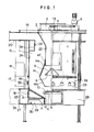
- a supply cylinder 2 is vertically provided at the center of the upper portion of a cylindrical separation chamber 1.
- a rotary shaft 4 is rotatably supported by a support member 3 at the center of said supply cylinder 2.
- Said rotary shaft 4 is driven by a variable speed electric motor or all speed motor 5 positioned in the upper portion of said supply cylinder 2.
- a preliminary dispersion board 6 is provided within said supply cylinder 2, and a dispersion board 8 is provided in a position under said supply cylinder 2 and above a discharge cylinder 7 for remainder after completion of wind classification as will be described hereunder.
- Said preliminary dispersion board 6 is in a conical configuration (the vertical angle is 90° in this embodiment) and an ejector plate 9 is provided on its declined surface radially and in parallel with the generatrix.
- Said dispersion board 8 is in a conical configuration with an umbrella shape at its center.
- the end portion 10 of said dispersion board 8 is raised upward outwardly (30° to 45° with respect to the horizontal line in this embodiment), and an ejector 11 is provided on its declined surface of the central portion thereof radially and in parallel with the generatrix.
- a vane 12 is provided at the under surface of the end portion 10 around its periphery in such a manner as to extend downward there- form.
- Said supply cylinder 2 forms a supply port 13 for raw material at a part of its upper end portion, and is formed with an annularly swollen portion or abacus bead shaped annularly swollen portion 14 having tapered over and under surfaces 14a and 14b at its lower portion in such a manner as that after the diameter thereof once becomes large around said preliminary dispersion board 6, it becomes smaller again as it goes downward.
- the separation chamber 1 is defined as an acceleration area 16 around the area where said supply cylinder 2 becomes large in its diameter to form said abacus bead shaped swollen portion 14.
- the upper area of said swollen portion 14 is defined as a separation area 15 and the lower area but above a ventilation member 18 is defined as a drop area 17.
- An air outlet 19 is provided at the upper portion of the separation area 15 of said separation chamber 1 and connected to an intake of a fan 22 by way of a tangential separator 21 through a duct 20.
- the discharge cylinder 7 for remainder after completion of wind classification is disposed generally in the vertical direction so that the upper end portion thereof is positioned under said dispersion board 8.
- the ventilation member 18 is interposed between said discharge cylinder 7 for remainder after completion of wind classification and the side wall 24 of the separation chamber 1.
- the upper end surface of the ventilation member 18 is extended downward (30° to 40° with respect to the horizontal line in this embodiment) gradually and inwardly between the side wall 24 of the separation chamber 1 and the upper end portion of said discharge cylinder 7. for remainder after completion of wind classification.
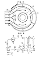
- the opened area of the ventilation member 18 is limited to a few percent of the total area of the ventilation member 18 in order to obtain an even speed of air flow.
- a chamber 25 is defined between the side wall 24 of separation chamber 1 at the lower portion of the ventilation member 18 and the side wall 23 of the discharge cylinder 7 for remainder after completion of wind classification.
- An annular chamber 28 having an air inlet 27 connecting to a duct 26 of the outlet of the fan 22 is provided on the periphery of said chamber 25.
- a plurality of ducts 29 are inserted from said annular chamber 28 into the inside of said chamber 25 toward the vicinity of the side wall 23 of said discharge cylinder 7 for remainder after completion of said wind classification for intercommunication.
- the total opened area of said ducts 29 is kept less than a half of the area of said air inlet 27, and a damper 30 for controlling air amount is disposed within the duct 29 in order to obtain an even air flow from the annular chamber 28 to the chamber 25.
- a rectification plate 31 which is annularly apertured is provided intermediate between the upper surface of the duct 29 of the chamber 25 and the ventilation member 18 in order to equalize the wind speed distribution both in the axial and peripheral directions.
- Dampers 32 and 33 are provided at the inlet and outlet of the fan 22 in order to balance the wind amount and the air resistance of the air circulation system for wind classification.
- the abacus bead shaped swollen portion 14 of the raw material supply cylinder 2 in the separation chamber 1 is vertically movably arranged in order to obtain the best separation condition according to the characteristic of the raw material in such a manner as that the distance between the abacus bead shaped swollen portion 14 and the dispersion board 8 is adjusted to shift the position of the acceleration area 16.
- an annularly protruded partition panel 34 adapted to define the air outlet 19 on the side wall of the separation chamber 1 is vertically adjustably disposed.
- the mounting position of the dispersion board 8 is vertically shiftable to a suitable position with respect to the acceleration area 16 and not to disturb the smooth flow of the raw material from the ventilation member 8 to the discharge cylinder 7 for remainder after completion of wind classification.
- the rotary shaft 4 on which the dispersion board 8 and the preliminary dispersion board 6 is mounted is made speed-variable in order to obtain desirable dispersion and spread of the raw material supplied into the separation chamber 1 from the supply cylinder 2.
- the vane, which is mounted on the under surface of the peripheral end portion 10 of said dispersion board 8, has such a configuration and number of blades as to compensate the scattering of the wind speed in the peripheral direction in the separation chamber 1 and maintain the floating time of the raw material adequately in the separation chamber 1, and also to circulate slightly the air in the separation chamber 1 to enhance the smooth flow of the raw material toward the discharge cylinder 7 for remainder after completion of wind classification from the above area of the ventilation member 18 without stagnancy.
- the air outlet 19 provided at the upper portion of the separation area 15 within the separation chamber 1 is divided into several portions (divided into 4 portions in this embodiment) in order to discharge the air without disturbing the distribution of the wind speed in the cylindrical separation chamber 1 and each of them is provided with a damper 3 for controlling the air amount.
- a plurality of secondary air intakes 36 are provided at the lower portion of the side wall 24 of the separation area 15 in the separation chamber 1 and each of them is provided with a damper for controlling the secondary air amount.
- the duct 26 of the outlet of the fan 22 is provided with an exhaust duct 37 in order to purify the circulation air within the ventilation system and enhance the smooth introduction of the secondary air into the separation chamber 1 and the air amount of exhaust air is controlled by a damper 38.
- the ventilation system is supported by the circulation system, and a balance of the air resistance and the wind amount is maintained so that no air- locker is required to shut out the flowing in-and- out of the air at the supply cylinder 2 of the separation chamber 1 and the discharge port 7 for remainder after completion of wind classification.
- the tobacco leaves (hereinafter referred to as the "raw material") supplied from the supply port 2 is unfastened and dispersed by means of the preliminary dispersion board 6 which is rotated by means of the rotary shaft 4.
- Said ejector plate 9 is useful for said unfastening and dispersion.
- the raw material is dropped toward the center of the dispersion board 8 along the side wall 23 of the supply cylinder 2 and evenly dispersed all over the periphery in the separation chamber 1 by the centrifugal force of said dispersion board 8.
- the ejector plate 11 and the raised up peripheral end portion 10 are useful for said dispersion.
- the peripheral end portion 10 renders a component force to the raw material in the upward direction.
- the air flow for separating and classifying the raw material dispersed within the separation chamber 1 is blown out by means of the ventilation member 18 to regulate the wind speed such that it is lower along the side wall 24 of the separation chamber 1 and the side wall 23 of the supply cylinder 2 than intermediate 24 of the separation chamber 1 and the side wall of the area.
- the raw material once blown up passing the acceleration area 16 is gradually reduced its speed in the separation area 15. Although the light weight raw material continues to climb upward, the heavy weight raw material starts dropping along the side wall 24 of the separation chamber 1 and the side wall 23 of the supply cylinder 2, and is dropped into the discharge cylinder 7 for remainder after completion of wind classification for separation.
- the configuration of the abacus bead shaped swollen portion 14 of the supply cylinder 2 forming the acceleration area 16 and the separation area 15 as well as the relationship of the portions between the abacus bead shaped swollen portion 14 and the dispersion board 8 and the positions between the dispersion board 8 and the ventilation member 18 are useful for said separation.
- Secondary air introduced from the secondary air intakes 36 formed on the side wall 24 of the separation chamber 1 affects the raw material dropping along the side wall 24 and blows up once again the light weight raw material accompanied by the heavy weight raw material.
- the slight air circulation within the separation chamber 1 by means of the vane 12 of the dispersion board 8 is useful for said separation because it improves the floating condition of the raw material.
- the light weight raw material climbed up the separation area 15 of the separation chamber 1 is guided to said tangential separator 21 through the upper air outlet 19 for collection.
- the present invention is constituted as mentioned in the foregoing, a comparatively light weight material to be separated, which is once blown up to the separation chamber by a wind speed and is dropped downward accompanied by a comparatively heavy weight material to be separated, is once again returned to the separation chamber by secondary air for re-classification.
- the present invention enables to improve the sharpness of separation considerably when compared with the prior art.
- the width of the separation area and that of the acceleration area are adjustably constituted, the best separation condition can be created depending on the characteristic of particular material to be separated.
Landscapes
- Life Sciences & Earth Sciences (AREA)
- Agronomy & Crop Science (AREA)
- Combined Means For Separation Of Solids (AREA)
- Sorting Of Articles (AREA)
- Manufacture Of Tobacco Products (AREA)
Applications Claiming Priority (2)
| Application Number | Priority Date | Filing Date | Title |
|---|---|---|---|
| JP13197883A JPS6025575A (ja) | 1983-07-21 | 1983-07-21 | たばこ葉等の風選分離装置 |
| JP131978/83 | 1983-07-21 |
Publications (2)
| Publication Number | Publication Date |
|---|---|
| EP0135999A1 EP0135999A1 (en) | 1985-04-03 |
| EP0135999B1 true EP0135999B1 (en) | 1987-07-08 |
Family
ID=15070677
Family Applications (1)
| Application Number | Title | Priority Date | Filing Date |
|---|---|---|---|
| EP19840304885 Expired EP0135999B1 (en) | 1983-07-21 | 1984-07-18 | Wind separation and classification equipment for tobacco leaves and the like |
Country Status (3)
| Country | Link |
|---|---|
| EP (1) | EP0135999B1 (OSRAM) |
| JP (1) | JPS6025575A (OSRAM) |
| DE (1) | DE3464545D1 (OSRAM) |
Families Citing this family (8)
| Publication number | Priority date | Publication date | Assignee | Title |
|---|---|---|---|---|
| US5263589A (en) * | 1992-09-18 | 1993-11-23 | Philip Morris Incorporated | Method of recovering tobacco from stemmery discard |
| CN103750536B (zh) * | 2011-12-31 | 2016-11-23 | 贵州中烟工业有限责任公司 | 梗丝分离系统 |
| CN104028465A (zh) * | 2014-06-24 | 2014-09-10 | 福建中烟工业有限责任公司 | 就地风选机及其循环风参数的控制方法和装置 |
| US9999892B2 (en) | 2015-09-03 | 2018-06-19 | Drsw, Llc | Method and apparatus of processing whole tobacco plants |
| EP3492184A1 (en) * | 2017-12-04 | 2019-06-05 | Klingmill AB | An apparatus for separating particles of different sizes |
| CN113017136B (zh) * | 2019-12-25 | 2024-08-30 | 秦皇岛烟草机械有限责任公司 | 一种打叶风分设备 |
| CN111765922B (zh) * | 2020-07-08 | 2021-07-06 | 昆明理工大学 | 一种基于打叶精细分风的叶片实时监测系统及监测方法 |
| CN113243547B (zh) * | 2021-05-11 | 2022-09-13 | 河北白沙烟草有限责任公司 | 一种烟丝加香滚筒自动调速方法及系统 |
Family Cites Families (4)
| Publication number | Priority date | Publication date | Assignee | Title |
|---|---|---|---|---|
| GB1030467A (en) * | 1964-03-28 | 1966-05-25 | Insinooritoimisto Engineering | An improved pneumatic classifier |
| DE1932361A1 (de) * | 1969-06-26 | 1971-01-14 | Hauni Werke Koerber & Co Kg | Verfahren und Vorrichtung zum pneumatischen Sichten von Tabakblatteilen aus einem Gemisch gerissener Tabakblaetter |
| JPS585655B2 (ja) * | 1980-01-11 | 1983-02-01 | 日本たばこ産業株式会社 | たばこ葉の風選式分離装置 |
| BE892501A (fr) * | 1982-03-15 | 1982-07-01 | Cbr Cementbedrijven Nv | Classificateur centrifuge pneumatique de solides pulverulents |
-
1983
- 1983-07-21 JP JP13197883A patent/JPS6025575A/ja active Granted
-
1984
- 1984-07-18 EP EP19840304885 patent/EP0135999B1/en not_active Expired
- 1984-07-18 DE DE8484304885T patent/DE3464545D1/de not_active Expired
Also Published As
| Publication number | Publication date |
|---|---|
| JPH0118713B2 (OSRAM) | 1989-04-06 |
| DE3464545D1 (en) | 1987-08-13 |
| EP0135999A1 (en) | 1985-04-03 |
| JPS6025575A (ja) | 1985-02-08 |
Similar Documents
| Publication | Publication Date | Title |
|---|---|---|
| CA1249245A (en) | Particle classifier | |
| US4689141A (en) | Separator for sorting particulate material, with a plurality of separately adjustable guide vane sets | |
| EP2020266B1 (en) | Powder classifying device | |
| US5622321A (en) | Mill classifier | |
| EP0172731B1 (en) | Classifier and controller for vertical mill | |
| CA1160993A (en) | Method and apparatus for classifying particles | |
| EP0135999B1 (en) | Wind separation and classification equipment for tobacco leaves and the like | |
| GB2041251A (en) | Pneumatic classifier | |
| US6273269B1 (en) | Air classifier with centrifugal action pneumatic separator having centrifugal action | |
| US4792393A (en) | Spiral air sifter having air regulation | |
| EP0060572B1 (en) | Drier, particularly for plastic material | |
| US6213307B1 (en) | Fluid-bed cleaner and grades sorter for particle form materials | |
| US4689140A (en) | Separator for sorting particulate material | |
| GB2163070A (en) | Separator for sorting particulate material | |
| CA2055124C (en) | Material dispersion apparatus | |
| EP3907437B1 (en) | Air cleaner | |
| US5791490A (en) | Separator for particulate materials | |
| GB2193448A (en) | Air classifier for granular materials | |
| EP0128392B1 (en) | A separator device for the separation of the components of edible meals or the like | |
| US2331850A (en) | Granular material classieier or purifier | |
| SU1316718A1 (ru) | Пневмосепаратор | |
| JP3132125B2 (ja) | 竪型ミル | |
| JPH0116543Y2 (OSRAM) | ||
| SU1609519A2 (ru) | Пневматический сортировальный стол | |
| CN119073650A (zh) | 一种梗签风分装置 |
Legal Events
| Date | Code | Title | Description |
|---|---|---|---|
| PUAI | Public reference made under article 153(3) epc to a published international application that has entered the european phase |
Free format text: ORIGINAL CODE: 0009012 |
|
| AK | Designated contracting states |
Designated state(s): DE GB IT |
|
| 17P | Request for examination filed |
Effective date: 19850430 |
|
| RAP1 | Party data changed (applicant data changed or rights of an application transferred) |
Owner name: JAPAN TOBACCO INC. |
|
| GRAA | (expected) grant |
Free format text: ORIGINAL CODE: 0009210 |
|
| ITF | It: translation for a ep patent filed | ||
| AK | Designated contracting states |
Kind code of ref document: B1 Designated state(s): DE GB IT |
|
| REF | Corresponds to: |
Ref document number: 3464545 Country of ref document: DE Date of ref document: 19870813 |
|
| PLBE | No opposition filed within time limit |
Free format text: ORIGINAL CODE: 0009261 |
|
| STAA | Information on the status of an ep patent application or granted ep patent |
Free format text: STATUS: NO OPPOSITION FILED WITHIN TIME LIMIT |
|
| 26N | No opposition filed | ||
| ITTA | It: last paid annual fee | ||
| PGFP | Annual fee paid to national office [announced via postgrant information from national office to epo] |
Ref country code: GB Payment date: 19990714 Year of fee payment: 16 |
|
| PGFP | Annual fee paid to national office [announced via postgrant information from national office to epo] |
Ref country code: DE Payment date: 19990716 Year of fee payment: 16 |
|
| PG25 | Lapsed in a contracting state [announced via postgrant information from national office to epo] |
Ref country code: GB Free format text: LAPSE BECAUSE OF NON-PAYMENT OF DUE FEES Effective date: 20000718 |
|
| GBPC | Gb: european patent ceased through non-payment of renewal fee |
Effective date: 20000718 |
|
| PG25 | Lapsed in a contracting state [announced via postgrant information from national office to epo] |
Ref country code: DE Free format text: LAPSE BECAUSE OF NON-PAYMENT OF DUE FEES Effective date: 20010501 |