EP0135687B1 - Gas evolving metal electrode - Google Patents
Gas evolving metal electrode Download PDFInfo
- Publication number
- EP0135687B1 EP0135687B1 EP84107873A EP84107873A EP0135687B1 EP 0135687 B1 EP0135687 B1 EP 0135687B1 EP 84107873 A EP84107873 A EP 84107873A EP 84107873 A EP84107873 A EP 84107873A EP 0135687 B1 EP0135687 B1 EP 0135687B1
- Authority
- EP
- European Patent Office
- Prior art keywords
- profiles
- electrode
- curvature
- gas
- metal electrode
- Prior art date
- Legal status (The legal status is an assumption and is not a legal conclusion. Google has not performed a legal analysis and makes no representation as to the accuracy of the status listed.)
- Expired
Links
- 229910052751 metal Inorganic materials 0.000 title claims description 19
- 239000002184 metal Substances 0.000 title claims description 19
- 238000005868 electrolysis reaction Methods 0.000 claims description 14
- 239000003513 alkali Substances 0.000 claims description 3
- QSHDDOUJBYECFT-UHFFFAOYSA-N mercury Chemical compound [Hg] QSHDDOUJBYECFT-UHFFFAOYSA-N 0.000 claims description 3
- 229910052753 mercury Inorganic materials 0.000 claims description 3
- 239000007787 solid Substances 0.000 claims description 2
- 239000007789 gas Substances 0.000 description 22
- RTAQQCXQSZGOHL-UHFFFAOYSA-N Titanium Chemical compound [Ti] RTAQQCXQSZGOHL-UHFFFAOYSA-N 0.000 description 20
- 239000010936 titanium Substances 0.000 description 18
- 229910052719 titanium Inorganic materials 0.000 description 18
- 238000010276 construction Methods 0.000 description 15
- 238000004519 manufacturing process Methods 0.000 description 13
- 239000004020 conductor Substances 0.000 description 9
- 238000009826 distribution Methods 0.000 description 9
- 239000000243 solution Substances 0.000 description 9
- 210000004027 cell Anatomy 0.000 description 7
- 238000000034 method Methods 0.000 description 7
- 230000008569 process Effects 0.000 description 7
- ZAMOUSCENKQFHK-UHFFFAOYSA-N Chlorine atom Chemical compound [Cl] ZAMOUSCENKQFHK-UHFFFAOYSA-N 0.000 description 5
- 239000000460 chlorine Substances 0.000 description 5
- 229910052801 chlorine Inorganic materials 0.000 description 5
- 239000000463 material Substances 0.000 description 5
- 230000008901 benefit Effects 0.000 description 4
- 150000002739 metals Chemical class 0.000 description 4
- 229910000510 noble metal Inorganic materials 0.000 description 4
- 229910000497 Amalgam Inorganic materials 0.000 description 3
- 230000004913 activation Effects 0.000 description 3
- 229910052782 aluminium Inorganic materials 0.000 description 3
- XAGFODPZIPBFFR-UHFFFAOYSA-N aluminium Chemical compound [Al] XAGFODPZIPBFFR-UHFFFAOYSA-N 0.000 description 3
- 230000000694 effects Effects 0.000 description 3
- 239000008151 electrolyte solution Substances 0.000 description 3
- 238000000926 separation method Methods 0.000 description 3
- OKTJSMMVPCPJKN-UHFFFAOYSA-N Carbon Chemical compound [C] OKTJSMMVPCPJKN-UHFFFAOYSA-N 0.000 description 2
- VEXZGXHMUGYJMC-UHFFFAOYSA-M Chloride anion Chemical compound [Cl-] VEXZGXHMUGYJMC-UHFFFAOYSA-M 0.000 description 2
- 239000002585 base Substances 0.000 description 2
- 230000001914 calming effect Effects 0.000 description 2
- 238000013461 design Methods 0.000 description 2
- 238000004090 dissolution Methods 0.000 description 2
- 239000003792 electrolyte Substances 0.000 description 2
- 229910002804 graphite Inorganic materials 0.000 description 2
- 239000010439 graphite Substances 0.000 description 2
- 239000007788 liquid Substances 0.000 description 2
- 238000012545 processing Methods 0.000 description 2
- 230000008439 repair process Effects 0.000 description 2
- 238000012546 transfer Methods 0.000 description 2
- 238000003466 welding Methods 0.000 description 2
- 229920001817 Agar Polymers 0.000 description 1
- RYGMFSIKBFXOCR-UHFFFAOYSA-N Copper Chemical compound [Cu] RYGMFSIKBFXOCR-UHFFFAOYSA-N 0.000 description 1
- 230000001133 acceleration Effects 0.000 description 1
- 239000008186 active pharmaceutical agent Substances 0.000 description 1
- 239000012300 argon atmosphere Substances 0.000 description 1
- 230000001680 brushing effect Effects 0.000 description 1
- 238000005266 casting Methods 0.000 description 1
- 210000002421 cell wall Anatomy 0.000 description 1
- 230000008859 change Effects 0.000 description 1
- 229910052802 copper Inorganic materials 0.000 description 1
- 239000010949 copper Substances 0.000 description 1
- 238000012937 correction Methods 0.000 description 1
- 230000007423 decrease Effects 0.000 description 1
- 230000008021 deposition Effects 0.000 description 1
- 238000007598 dipping method Methods 0.000 description 1
- 238000005265 energy consumption Methods 0.000 description 1
- 238000005516 engineering process Methods 0.000 description 1
- 230000007717 exclusion Effects 0.000 description 1
- 238000000605 extraction Methods 0.000 description 1
- 230000002349 favourable effect Effects 0.000 description 1
- 239000012212 insulator Substances 0.000 description 1
- 230000008018 melting Effects 0.000 description 1
- 238000010309 melting process Methods 0.000 description 1
- 150000002736 metal compounds Chemical class 0.000 description 1
- 238000003825 pressing Methods 0.000 description 1
- 238000004080 punching Methods 0.000 description 1
- 238000005096 rolling process Methods 0.000 description 1
- 238000005507 spraying Methods 0.000 description 1
- 238000007751 thermal spraying Methods 0.000 description 1
- 230000007704 transition Effects 0.000 description 1
Images
Classifications
-
- C—CHEMISTRY; METALLURGY
- C25—ELECTROLYTIC OR ELECTROPHORETIC PROCESSES; APPARATUS THEREFOR
- C25B—ELECTROLYTIC OR ELECTROPHORETIC PROCESSES FOR THE PRODUCTION OF COMPOUNDS OR NON-METALS; APPARATUS THEREFOR
- C25B11/00—Electrodes; Manufacture thereof not otherwise provided for
- C25B11/02—Electrodes; Manufacture thereof not otherwise provided for characterised by shape or form
Definitions
- the present invention relates to a gas-evolving metal electrode, e.g. can be used in particular as an anode in amalgam cells for chlor-alkali electrolysis.
- the use of titanium as the electrode base material allows a large number of different geometrical designs in comparison to graphite in order to fulfill the required function as a gas-generating electrode.
- the production of very flat electrode surfaces (+ 1 mm difference / m 2 electrode surface) has become possible. This in turn allows the distance from the anode to the cathode to be significantly reduced.
- the electrolyte solution in the case of chloralkali electrolysis the NaCI solution, has an electrical resistance, the aim is to reduce the voltage or energy losses caused thereby to a minimum by keeping the distance between the electrodes as small as possible.
- OE-AS 20 41 250 an electrode construction is described in which the working electrode surface, that of the cathode, e.g. in chlorine production using the amalgam process, the mercury cathode, made of expanded metal, perforated sheet metal, wire mesh or the like. is formed.
- a U-shaped conductor rail is used for uniform current distribution, which must also give the expanded metal the necessary mechanical rigidity in order to achieve the required planarity. It is easy to see that the production of such a conductor rail is very problematic, since titanium sheets have to be pressed into a U-shape and titanium tends to “spring back” after such a pressing process.
- notches have to be incorporated into this conductor rail , which reduce the stresses that occur when the expanded metal is welded to the rail, and also allow subsequent correction of the working surface of the anode in order to achieve a better planarity of the electrode surface
- the gas bubbles formed are now discharged upwards through the openings in the expanded metal, perforated plate, etc.
- openings must therefore also be worked into the relatively large conductor rail
- Conductor rails can also be fixed with stable cross struts.
- the titanium sheathing of the aluminum must be absolutely tight at all points, in particular also at the weld seams, since with the slightest damage to the titanium sheath, the electrode is rapidly destroyed by the anodic dissolution of the aluminum which takes place in the presence of chloride.
- US Pat. No. 4,055,847 describes a complicated structure for achieving the necessary strength of the electrode surface and for achieving a good current distribution. It consists of a spider-shaped power distribution system, in which additional support ribs are required. As stated in the patent specification, melting and casting processes are necessary to produce the corresponding structures. However, as is generally known, these are complex and expensive in the processing of metals, in particular titanium or valve metals, since valve metals can only be melted in an argon atmosphere with a strict exclusion of air for metallurgical reasons. Another possible solution is shown in DE-OS 29 49 495. However, this construction also requires a primary and secondary power distribution system, which - analogous to that of DE-OS 1814 567 - require high manufacturing and material costs. Due to the relatively open construction of this system from flat profiles, however, gas bubble tearing and mass transfer on the electrode surface are to be improved.
- DE-OS 30 08 116 describes an electrode construction which has only a primary distribution system, but which is also relatively complex.
- the oval profiles used here are created by flattening the round bars. This should achieve a ratio of working to projected electrode area of> 1.
- no attention is paid here cf. J. Cramer, Chem. Ing. Techn. 52, 1980, pp. 48-51 that the solution to be electrolyzed opposes the passage of the electric current, so that the electrode surfaces are all the less to the course of the electrolysis reaction, ie Gas evolution contribute the further away they are from the counter electrode.
- the reason for this is the fact that the streamlines are looking for the shortest possible route as they pass through the solution to be electrolyzed.
- German utility model 72 07 894 describes a gas-developing electrode which consists of a plate which is interspersed with channels which widen near and to a surface of the electrode. These channels can be continuously conical or venturi-like. This is intended to achieve an improved electrolyte circulation. Apart from the fact that this electrode can only be produced with complex manufacturing technology, this electrode has not found any technical use, since plate-shaped electrodes in particular have disadvantages with regard to gas removal.
- a gas-developing metal electrode for electrolysis cells in particular anode for amalgam cells for chloralkali electrolysis, which consists of profiles arranged parallel to one another in a horizontal plane, the effective electrode surface facing the counterelectrode being curved and the profiles having a transverse profile with it a power supply provided power supply are connected to each other, which is characterized in that the curvature of the effective electrode surface in the area of the gaps into one with a smaller radius (r) passes, the radius (R) determining the curvature of the effective electrode surface being from 7 to 180 mm and the smaller radius (r) being 0.5 to 4 mm, and the profiles being closed off at the top by two side surfaces which emerge tangentially from the curvature (22, 25), which form an angle (alpha) of 20 to 120 ° at their intersection.
- Solid or hollow profiles can be used as profiles for the electrodes according to the invention.
- full profiles more titanium is required than with hollow profiles, but this disadvantage is offset by the advantage that the resistance is reduced and the voltage drop is reduced.
- full profiles are easier to process.
- the effective electrode area i.e. the surface which can be projected onto the counterelectrode is curved in such a way that the curvature increases from the center towards the edges.
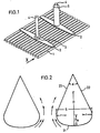
- FIG. 1 is a perspective view
- FIG. 2 in which two profiles are shown enlarged from viewing direction X.
- the effective electrode surface consists of profiles arranged parallel to each other.
- the mechanical and electrical connection of these electrode profiles to one another is carried out by welding with one or more titanium webs (2) which have a shape specially developed for the purpose described. Titanium bodies (5) with an internal thread are attached to these webs.
- the internal thread serves to receive a power supply (4), e.g. a copper bolt. If necessary, this can be protected from the electrolyte solution (and thus anodic dissolution) by a welded-on titanium tube (5).
- the power supply to the individual electrode profiles takes place exclusively through a simple primary conductor system made of titanium webs (2). This is easy to manufacture from commercially available titanium sheets of appropriate thickness (matched to the current load) by simply punching them out.
- FIG. 2 two hollow electrode profiles according to the invention, according to viewing direction X from FIG. 1, are shown schematically, enlarged compared to FIG.
- the work surface 21, i.e. the surface which can be projected onto the counterelectrode is curved according to the invention in such a way that the curvature on the sides, i.e. to the neighboring profile or to the cell wall becomes stronger.
- the curvature is determined by the radius R and the two smaller radii r.
- the hollow profile is closed at the top by the two meeting side surfaces 22 and 25, which are continued tangentially from the curved working surface.
- the cross section of the gap zone between two profiles is given the profile of a nozzle-shaped rounded inlet zone and a calming zone which widens upward like a diffuser.
- the gas bubbles formed on the work surface move towards the edges of the profiles and, due to the intensifying curvature, experience a desired uniform acceleration in contrast to an abrupt tearing off of the gas bubbles on an edge-shaped profile, which results in a higher pressure loss connected is.
- the gas is brought to the speed required to pass the narrowest point of the gap between two profiles with a minimal pressure loss. Due to the lower pressure drop, the gas bubbles reach a higher speed, which entrains a larger amount of liquid.
- the profiles should have certain geometric dimensions have, which are selected depending on the cell conditions.
- the work surface has less curvature in the middle than at the edges.
- the curvature in the central part is determined by a circular line whose radius R is 7-180 mm, preferably 15 to 25 mm, while on both sides the curvature becomes stronger and in a circular line with a radius r of 0.5 to 4 mm passes.
- the two radii should be chosen so that R / r i: 5.
- the inventive design of the work surface ensures that, due to the relatively large radius of the circular line in the central region, an almost optimal, uniform distance of the work surface from the counter-cathode is ensured, the relatively small curvature of which, however, is already sufficient for rapid removal of the gas bubbles formed. Due to the stronger rounding at the transition of the work surface into the tangential side surfaces, edges are avoided at this point, which, as is known, are subject to increased wear.
- the height of the circular arc results (ie the greatest distance between the web width S and the working surface 21), which, however, should meet the condition that is from 5 to 1800.
- the inclination of the side surfaces can also be varied within wide limits. This inclination is determined by the angle with which they meet and which can expediently be from 20 ° to 120 °.
- the technical outlay for producing the metal electrodes according to the invention is low.
- the individual electrode profiles (5) need only be welded continuously to the distributor webs (2). Notches into which the profiles are inserted can be incorporated into these webs for better fixation.
- the relatively long weld seam ensures good current transfer from the distributor web to the profiles.
- the electrode construction according to the invention is characterized by an extraordinarily simple structure, its mechanical strength is excellent, essentially also due to the cross-sectional shape of the profiles according to the invention.
- the electrodes are also very easy to repair. If a profile is damaged, e.g. by short-circuiting, the respective electrode profiles can easily be exchanged individually or brought to the required planarity by corresponding messages.
- the claimed electrode From the description of the claimed electrode it also follows that only the actually effective surface of the electrode base body has to be provided with an active layer, since here there is a construction in which different partial areas of the profiles are each optimized with regard to the task to be performed.
- the side opposite the counterelectrode is so designed that the working electrode surface can optimally fulfill its function in the electrolysis process.
- the other sections of the electrode profile are optimized according to hydrodynamic criteria and simple manufacture.
- the construction is therefore very suitable for applying the activation solution by dipping, rolling or brushing. Since it is relatively easy to coat only the working electrode surface (which is desirable but not a requirement), the amount of activation solution required is reduced to a minimum. This is particularly advantageous when using activation solutions which contain expensive noble metals or noble metal compounds, for example in the case of the known Ru0 2- containing active layers for anodic chlorine deposition.
- this construction can be coated very well with the aid of spraying processes - in particular thermal spraying processes - since the working electrode surface has no sharp edges and since it is not necessary to coat side surfaces which are difficult to access.
Description
Die vorliegende Erfindung betrifft eine gasentwickelnde Metallelektrode, die z.B. insbesondere als Anode in Amalgamzellen für die Chloralkali-Elektrolyse eingesetzt werden kann.The present invention relates to a gas-evolving metal electrode, e.g. can be used in particular as an anode in amalgam cells for chlor-alkali electrolysis.
Bei der Herstellung von z.B. Chlor durch Elektrolyse wäßriger Alkalichloridlösungen werden heute im allgemeinen Titananoden mit edelmetallhaltigen Aktivschichten eingesetzt. Diese sogenannten dimensionsstabilen Anoden haben gegenüber den vorher hauptsächlich eingesetzten Graphitelektroden den Vorteil, daß sich die äußeren Abmessungen während des Betriebs nicht ändern. Der Nachteil dieser Anoden liegt in den relativ hohen Herstellungskosten, bedingt durch den hohen Preis des Titans und dessen aufwendige Bearbeitung sowie auch durch die Verwendung von Edelmetall in der Aktivschicht.In the manufacture of e.g. Chlorine by electrolysis of aqueous alkali chloride solutions are generally used today titanium anodes with active layers containing noble metals. These so-called dimensionally stable anodes have the advantage over the previously mainly used graphite electrodes that the external dimensions do not change during operation. The disadvantage of these anodes lies in the relatively high production costs, due to the high price of titanium and its complex processing, as well as the use of noble metal in the active layer.
Die Verwendung von Titan als Elektrodengrundmaterial erlaubt jedoch im Vergleich zu Graphit eine Vielzahl unterschiedlicher geometrischer Konstruktionen, um die erforderliche Funktion als gaserzeugende Elektrode zu erfüllen. Insbesondere ist die Herstellung sehr ebener Elektrodenflächen (+ 1 mm Differenz/m2 Elektrodenfläche) möglich geworden. Dies erlaubt wiederum, den Abstand von Anode zu Kathode deutlich zu verringern. Da die Elektrolytlösung, im Fall der Chloralkalielektrolyse die NaCI-Lösung, einen elsktrischen Widerstand besitzt, strebt man danach, die hierdurch verursachten Spannungs- bzw. Energieverluste auf ein Mindestmaß zu reduzieren, indem der Abstand zwischen den Elektroden möglichst klein gehalten wird.However, the use of titanium as the electrode base material allows a large number of different geometrical designs in comparison to graphite in order to fulfill the required function as a gas-generating electrode. In particular, the production of very flat electrode surfaces (+ 1 mm difference / m 2 electrode surface) has become possible. This in turn allows the distance from the anode to the cathode to be significantly reduced. Since the electrolyte solution, in the case of chloralkali electrolysis the NaCI solution, has an electrical resistance, the aim is to reduce the voltage or energy losses caused thereby to a minimum by keeping the distance between the electrodes as small as possible.
Gleichzeitig muß jedoch ein gewisser Mindestabstand zur Durchführung der Elektrolysereaktion gewährleistet werden, der auch sicherstellt, daß nach Möglichkeit keine Kurzschlüsse erfolgen können.At the same time, however, a certain minimum distance must be ensured for carrying out the electrolysis reaction, which also ensures that, if possible, no short circuits can occur.
In der OE-AS 20 41 250 wird eine Elektrodenkonstruktion beschrieben, bei der die arbeitende Elektrodenfläche, die der Kathode, z.B. bei der Chlorherstellung nach dem Amalgamverfahren der Quecksilberkathode, gegenübersteht, aus Streckmetall, Lochblech, Orahtnetz o.a. gebildet wird. Zur gleichmäßigen Stromverteilung dient eine U-förmige Leiterschiene, die dem Streckmetall auch die notwendige mechanische Steifigkeit verleihen muß, um die geforderte Planarität zu erreichen. Es ist leicht ersichtlich, daß die Herstellung einer derartigen Leiterschiene sehr problematisch ist, da zu deren Herstellung Titanbleche in eine U-Form gepreßt werden müssen und Titan nach einem solchen Preßvorgang gerne 'zurückfedert". Darüber hinaus ist es erforderlich, in diese Leiterschiene Kerben einzuarbeiten, die eine Verringerung der Spannungen, die beim Anschweißen des Streckmetalls an die Schiene entstehen, bewirken. Sie sollen auch eine nachträgliche Korrektur der Arbeitsfläche der Anode zur Erzielung einer besseren Planarität der Elektrodenfläche erlauben. Nachteilig ist außerdem, daß für diese Konstruktion der Leiterschiene große Mengen an Titan verbraucht werden. Während der Elektrolysereaktion werden nun die gebildeten Gasblasen durch die Öffnungen im Streckmetall, Lochblech usw. nach oben abgeleitet. Zur weiteren Gasableitung müssen deshalb auch in die relativ großflächige Leiterschiene Öffnungen eingearbeitet werden. Bei größeren Elektrodenflächen müssen die einzelnen Leiterschienen zusätzlich durch stabile Querverstrebungen fixiert werden.In OE-AS 20 41 250 an electrode construction is described in which the working electrode surface, that of the cathode, e.g. in chlorine production using the amalgam process, the mercury cathode, made of expanded metal, perforated sheet metal, wire mesh or the like. is formed. A U-shaped conductor rail is used for uniform current distribution, which must also give the expanded metal the necessary mechanical rigidity in order to achieve the required planarity. It is easy to see that the production of such a conductor rail is very problematic, since titanium sheets have to be pressed into a U-shape and titanium tends to “spring back” after such a pressing process. In addition, notches have to be incorporated into this conductor rail , which reduce the stresses that occur when the expanded metal is welded to the rail, and also allow subsequent correction of the working surface of the anode in order to achieve a better planarity of the electrode surface During the electrolysis reaction, the gas bubbles formed are now discharged upwards through the openings in the expanded metal, perforated plate, etc. For further gas discharge, openings must therefore also be worked into the relatively large conductor rail Conductor rails can also be fixed with stable cross struts.
Ein gutes Entweichen der Gasblasen soll bei der in der DE-OS 1814 567 beschriebenen Konstruktion durch ein aufwendiges System aus Primär- und Sekundärleiterschienen bewirkt werden, wobei dieses System auch der arbeitenden Elektrodenfläche die nötige Festigkeit (und somit Planarität) verleihen soll. Diese Lösung muß mit hohem Material- und Herstellungsaufwand erkauft werden, vor allen Dingen, da viele Schweißvorgänge und eine exakte Justierung der Einzelteile erforderlich sind.A good escape of the gas bubbles in the construction described in DE-OS 1814 567 is to be brought about by a complex system of primary and secondary conductor rails, this system also giving the working electrode surface the necessary strength (and thus planarity). This solution has to be bought with high material and manufacturing costs, especially since many welding processes and an exact adjustment of the individual parts are required.
Eine ähnliche Konstruktion wird in der DE-OS 20 45 560 beschrieben. Hier wird die Festigkeit der Elektrodenfläche, die aus einer im wesentlichen sich horizontal erstreckenden durchbrochenen Titanstruktur besteht, durch parallel im Abstand auf der Struktur angeordnete runde Stäbe erhöht, die auch die Stromverteilung sicherstellen. Diese Rundstäbe sind mit quer hierzu angeordneten rechteckigen Schienen verbunden, die die Aufgabe der Stromzuführung übernehmen. Der Kern dieser Stäbe und Schienen besteht aus Aluminium, das wiederum von Titan umgeben ist. Auch diese Anodenzusammenstellung basiert auf einem aufwendigen Herstellungsverfahren. Darüber hinaus muß die Titanummantelung des Aluminiums an allen Stellen, insbesondere auch an den Schweißnähten, absolut dicht sein, da bei der geringsten Beschädigung des Titanmantels eine rasche Zerstörung der Elektrode durch die in Gegenwart von Chlorid ablaufende anodische Auflösung des Aluminiums erfolgt.A similar construction is described in DE-OS 20 45 560. Here, the strength of the electrode surface, which consists of a substantially horizontally extending perforated titanium structure, is increased by round rods which are arranged in parallel at a distance on the structure and which also ensure the current distribution. These round bars are connected to rectangular rails arranged transversely thereto, which take on the task of supplying power. The core of these rods and rails is made of aluminum, which in turn is surrounded by titanium. This anode assembly is also based on a complex manufacturing process. In addition, the titanium sheathing of the aluminum must be absolutely tight at all points, in particular also at the weld seams, since with the slightest damage to the titanium sheath, the electrode is rapidly destroyed by the anodic dissolution of the aluminum which takes place in the presence of chloride.
Eine ähnliche Konstruktion wird in der DE-DS 27 21 958 beschrieben, bei der zur Verbesserung der Stromleitung und Einsparung von teurem Titan wesentliche Bestandteile der Elektrode aus Titanteilen bestehen, deren Kern aus Stäben aus anderen Metallen gefüllt ist, die in einem unter Betriebstemperatur vorwiegend flüssigen, stromleitenden Material eingebettet sind.A similar construction is described in DE-DS 27 21 958, in which essential components of the electrode consist of titanium parts, the core of which is filled with rods made of other metals, which are predominantly liquid at operating temperature, in order to improve the power conduction and save expensive titanium , conductive material are embedded.
Um eine gute Gasableitung zu erzielen, werden in der DE-OS 25 25 497 vertikal angeordnete Titanstege mit rechteckigem Querschnitt in einem bestimmten Abstand so miteinander verbunden, daß der Gasblasenabzug durch die resultierenden Spalte erfolgen kann. Darüber hinaus wird gefordert, daß diese Stege auch an den Seiten aktiviert werden, damit auch hier eine Chlorabscheidung stattfinden kann. Dies soll die effektiv wirksame Elektrodenfläche erhöhen, da die der Hg-Kathode gegenüberliegenden horizontalen Abschnitte der Stege - verglichen mit der geometrischen Fläche der gesamten Elektrode - nur einen geringen Flächenanteil ausmachen. Wie neuere Untersuchungen ergeben haben (Chem. Ing. Techn. 52 (1980), 48-51), kann jedoch als gesichert angesehen werden, daß diese Seitenflächen aufgrund ihres größeren Abstandes von der Gegenelektrode keine relevanten Beiträge zur Chlorabscheidung liefern können. Außerdem müssen die an der horizontalen Fläche abgeschiedenen, elektrisch isolierende Gasblasen diese Zwischenräume passieren, was den Stromfluß in diesem Bereich zusätzlich behindert.In order to achieve good gas discharge, in DE-OS 25 25 497 vertically arranged titanium webs with a rectangular cross-section are connected to one another at a certain distance so that the gas bubbles can be drawn off through the resulting gaps. In addition, it is required that these webs are also activated on the sides so that chlorine separation can also take place here. This is said to increase the effective electrode area since the horizontal sections of the webs opposite the mercury cathode make up only a small proportion of the area compared to the geometrical area of the entire electrode. However, as recent studies have shown (Chem. Ing. Techn. 52 (1980), 48-51), it can be considered certain that these side surfaces cannot make any relevant contributions to chlorine separation due to their greater distance from the counterelectrode. In addition, the electrically insulating gas bubbles deposited on the horizontal surface must pass through these spaces, which additionally impedes the flow of current in this area.
In der US-Patentschrift 4 055 847 wird eine komplizierte Struktur zur Erzielung der notwendigen Festigkeit der Elektrodenfläche und zur Erzielung einer guten Stromverteilung beschrieben. Sie besteht aus einem spinnenförmigen Stromverteilersystem, bei dem noch zusätzlich Trägerrippen notwendig sind. Wie in der Patentschrift ausgeführt, sind zur Herstellung der entsprechenden Strukturen Schmelz- und Gießvorgänge notwendig. Diese sind jedoch, wie allgemein bekannt, bei der Verarbeitung von Metallen, insbesondere Titan bzw. Ventilmetallen, aufwendig und teuer, da Ventilmetalle aus metallurgischen Gründen nur unter strengem Luftausschluß in Argonatmosphäre geschmolzen werden können. Eine weitere Lösungsmöglichkeit wird in der DE-OS 29 49 495 aufgezeigt. Diese Konstruktion erfordert jedoch ebenfalls ein primäres und sekundäres Stromverteilungssystem, die - analog zu demjenigen der DE-OS 1814 567 - hohen Herstellungs- und Materialaufwand erfordern. Durch die relativ offene Konstruktion dieses Systems aus Flachprofilen soll jedoch der Gasblasenabriß und Stoffaustausch an der Elektrodenoberfläche verbessert werden.US Pat. No. 4,055,847 describes a complicated structure for achieving the necessary strength of the electrode surface and for achieving a good current distribution. It consists of a spider-shaped power distribution system, in which additional support ribs are required. As stated in the patent specification, melting and casting processes are necessary to produce the corresponding structures. However, as is generally known, these are complex and expensive in the processing of metals, in particular titanium or valve metals, since valve metals can only be melted in an argon atmosphere with a strict exclusion of air for metallurgical reasons. Another possible solution is shown in DE-OS 29 49 495. However, this construction also requires a primary and secondary power distribution system, which - analogous to that of DE-OS 1814 567 - require high manufacturing and material costs. Due to the relatively open construction of this system from flat profiles, however, gas bubble tearing and mass transfer on the electrode surface are to be improved.
In der DE-OS 30 08 116 wird eine Elektrodenkonstruktion beschrieben, die nur ein primäres Verteilersystem besitzt, das jedoch ebenfalls relativ aufwendig ist. Die hier verwendeten Ovalprofile entstehen durch Abplatten der Rundstäbe. Hierdurch soll ein Verhältnis von arbeitender zu projezierter Elektrodenfläche von > 1 erreicht werden. Hierbei wird jedoch nicht beachtet (vgl. J. Cramer, Chem. Ing. Techn. 52,1980, S. 48-51), daß die zu elektrolysierende Lösung dem Durchtritt des elektrischen Stromes einen Widerstand entgegensetzt, so daß die Elektrodenflächen um so weniger zum Ablauf der Elektrolysereaktion, d.h. Gasentwicklung beitragen, je weiter sie von der Gegenelektrode entfernt sind. Begründung hierfür ist die Tatsache, daß sich die Stromlinien bei ihrem Durchgang durch die zu elektrolysierende Lösung nach Möglichkeit den kürzesten Weg suchen. Dieser Sachverhalt soll in folgenden Ausführungen noch weiter verdeutlicht werden: Sicher erfolgt bei dieser Konstruktion die Gasblasenabführung von der arbeitenden Elektrodenfläche infolge der starken Krümmung rascher als bei den in der DE-OS 29 49 495 verwendeten Flachprofilen, jedoch haben diese relativ kleinen Krümmungsgradien den Nachteil, daß in den Bereichen, die der Kathode am nächsten liegen, bei der Elektrolyse sehr hohe Stromdichten herrschen. Dies verursacht höhere Abscheidepotentiale und somit auch eine höhere Zellspannung bzw. Energieverbrauch. Die von der Kathode weiter entfernt liegenden Bereiche sind durch eine dickere Elektrolytschicht mit entsprechend höherem elektrischen Widerstand benachteiligt. Auch dies wirkt sich auf die Zellspannung ungünstig aus.DE-OS 30 08 116 describes an electrode construction which has only a primary distribution system, but which is also relatively complex. The oval profiles used here are created by flattening the round bars. This should achieve a ratio of working to projected electrode area of> 1. However, no attention is paid here (cf. J. Cramer, Chem. Ing. Techn. 52, 1980, pp. 48-51) that the solution to be electrolyzed opposes the passage of the electric current, so that the electrode surfaces are all the less to the course of the electrolysis reaction, ie Gas evolution contribute the further away they are from the counter electrode. The reason for this is the fact that the streamlines are looking for the shortest possible route as they pass through the solution to be electrolyzed. This fact should be clarified in the following explanations: In this construction, the gas bubble removal from the working electrode surface takes place more quickly due to the strong curvature than with the flat profiles used in DE-OS 29 49 495, but these relatively small degrees of curvature have the disadvantage that that in the areas closest to the cathode, there are very high current densities during electrolysis. This causes higher separation potentials and thus also a higher cell voltage or energy consumption. The areas further away from the cathode are disadvantaged by a thicker electrolyte layer with a correspondingly higher electrical resistance. This also has an unfavorable effect on the cell voltage.
In dem deutschen Gebrauchsmuster 72 07 894 ist schließlich eine gasentwickelnde Elektrode beschrieben, die aus einer Platte besteht, die mit nahe der und zu einer Oberfläche der Elektrode hin sich erweiternden Kanälen durchsetzt ist. Diese Kanäle können durchgehend konisch oder venturiartig ausgebildet sein. Hierdurch soll eine verbesserte Elektrolytzirkulation erzielt werden. Abgesehen davon, daß diese Elektrode fertigungstechnisch nur aufwendig zu realisieren ist, hat diese Elektrode keine technische Verwendung gefunden, da gerade plattenförmige Elektroden bezüglich der Gasabführung prinzipielle Nachteile aufweisen.Finally, German utility model 72 07 894 describes a gas-developing electrode which consists of a plate which is interspersed with channels which widen near and to a surface of the electrode. These channels can be continuously conical or venturi-like. This is intended to achieve an improved electrolyte circulation. Apart from the fact that this electrode can only be produced with complex manufacturing technology, this electrode has not found any technical use, since plate-shaped electrodes in particular have disadvantages with regard to gas removal.
Der vorliegenden Erfindung lag nun die Aufgabe zugrunde, eine Form für eine gasentwickelnde Metallelektrode zu entwickeln, die folgende Eigenschaften besitzen sollte:
- - Möglichst geringer Materialeinsatz zur Herstellung des Elektrodenkörpers.
- - Trotz vereinfachter Konstruktion gute mechanische Festigkeit bei gleichzeitig hoher Reparaturfreundlichkeit und guter Planarität der Elektrodenoberfläche.
- - Die Elektrodenprofile sollten nach Möglichkeit keine Kanten aufweisen, da an diesen Stellen erhöhter Verschleiß der Aktivschicht auftritt.
- - Der Gasblasenabriß sollte durch neue Profilquerschnitte, die nach hydrodynamischen Gesichtspunkten gestaltet sind, verbessert werden. Da Gasblasen für den Stromdurchgang 'Isolatoren" darstellen, dient deren rascher Abtransport einer Erniedrigung des Energiebedarfs für die Elektrolyse.
- - Die Verteilung der Stromlinien auf der arbeitenden Elektrodenfläche sollte möglichst gleichmäßig sein.
- - As little material as possible for the manufacture of the electrode body.
- - Despite the simplified construction, good mechanical strength combined with high ease of repair and good planarity of the electrode surface.
- - If possible, the electrode profiles should have no edges, as increased wear of the active layer occurs at these points.
- - The gas bubble tear should be improved by new profile cross sections, which are designed according to hydrodynamic aspects. Since gas bubbles represent 'insulators' for the passage of current, their rapid removal serves to lower the energy requirement for electrolysis.
- - The distribution of the current lines on the working electrode surface should be as even as possible.
Diese Aufgabe wird gelöst durch eine gasentwickelnde Metallelektrode für Elektrolysezellen, insbesondere Anode für Amalgamzellen für die Chloralkalielektrolyse, die aus in einer horizontalen Ebene parallel zueinander angeordneten Profilen besteht, wobei die der Gegenelektrode zugekehrte wirksame Elektrodenfläche gekrümmt ist und die Profile mit quer da zu verlaufenden, mit einer Stromzuführung versehenen Stromverteilern miteinander verbunden sind, die dadurch gekennzeichnet ist, daß die Krümmung der wirksamen Elektrodenfläche im Bereich der Spalte in eine solche mit kleinerem Radius (r) übergeht, wobei der die Krümmung der wirksamen Elektrodenfläche bestimmende Radius (R) von 7 bis 180 mm und der kleinere Radius (r) 0,5 bis 4 mm beträgt, und daß die Profile nach oben abgeschlossen werden durch zwei aus der Krümmung tangential hervorgehenden Seitenflächen (22, 25), die an ihrem Schnittpunkt einen Winkel (alpha) von 20 bis 120° einschließen.This object is achieved by a gas-developing metal electrode for electrolysis cells, in particular anode for amalgam cells for chloralkali electrolysis, which consists of profiles arranged parallel to one another in a horizontal plane, the effective electrode surface facing the counterelectrode being curved and the profiles having a transverse profile with it a power supply provided power supply are connected to each other, which is characterized in that the curvature of the effective electrode surface in the area of the gaps into one with a smaller radius (r) passes, the radius (R) determining the curvature of the effective electrode surface being from 7 to 180 mm and the smaller radius (r) being 0.5 to 4 mm, and the profiles being closed off at the top by two side surfaces which emerge tangentially from the curvature (22, 25), which form an angle (alpha) of 20 to 120 ° at their intersection.
Bei den erfindungsgemäßen Elektroden können als Profile Voll- oder Hohlprofile eingesetzt werden. Bei Verwendung von Vollprofilen wird zwar mehr Titan benötigt als bei Hohlprofilen, diesem Nachteil steht jedoch der Vorteil gegenüber, daß der Widerstand herabgesetzt und der Spannungsabfall verringert wird. Darüber hinaus lassen sich Vollprofile leichter verarbeiten.Solid or hollow profiles can be used as profiles for the electrodes according to the invention. When using full profiles, more titanium is required than with hollow profiles, but this disadvantage is offset by the advantage that the resistance is reduced and the voltage drop is reduced. In addition, full profiles are easier to process.
Weiterhin ist erfindungsgemäß die wirksame Elektrodenfläche, d.h. die auf die Gegenelektrode projizierbare Fläche in der Weise gekrümmt, daß die Krümmung von der Mitte zu den Rändern hin zunimmt.Furthermore, the effective electrode area, i.e. the surface which can be projected onto the counterelectrode is curved in such a way that the curvature increases from the center towards the edges.
Bei der Krümmung des mittleren Teiles sind zwei gegenläufige Forderungen zu erfüllen, nämlich
- 1) einerseits sollte die Arbeitsfläche möglichst eben sein, wodurch ein gleichmäßiger Abstand Anodenfläche zu Gegenelektrode gewährleistet ist, was für eine gleichmäßige Stromdichteverteilung günstig, für den erforderlichen Gasblasenabtransport jedoch ungünstig ist und
- 2) andererseits sollte die Arbeitsfläche möglichst gekrümmt sein, wodurch sich die oben beschriebenen Vor- bzw. Nachteile umkehren.
- 1) on the one hand, the working surface should be as flat as possible, which ensures a uniform distance between the anode surface and the counterelectrode, which is favorable for a uniform current density distribution, but is unfavorable for the necessary gas bubble removal and
- 2) on the other hand, the work surface should be as curved as possible, which reverses the advantages and disadvantages described above.
Im folgenden sei die erfindungsgemäße gasentwickelnde Metallelektrode an Hand der Figuren 1, die eine perspektivische Ansicht und der Figur 2, in der zwei Profile aus Blickrichtung X vergrößert dargestellt sind, erläutert.In the following, the gas-developing metal electrode according to the invention will be explained with reference to FIG. 1, which is a perspective view and FIG. 2, in which two profiles are shown enlarged from viewing direction X.
Die wirksame Elektrodenfläche besteht aus parallel zueinander angeordneten Profilen. Die mechanische und elektrische Verbindung dieser Elektrodenprofile untereinander erfolgt durch Verschweißen mit einem oder mehreren Titanstegen (2), die eine speziell für den beschriebenen Zweck entwickelte Form besitzen. Auf diesen Stegen werden Titankörper (5) mit einem Innengewinde angebracht. Das Innengewinde dient zur Aufnahme einer Stromzuführung (4), z.B. einem Kupferbolzen. Dieser kann bei Bedarf durch ein aufgeschweißtes Titanrohr (5) vor der Elektrolytlösung (und somit anodischer Auflösung) geschützt werden. Die Stromzuführung zu den einzelnen Elektrodenprofilen erfolgt ausschließlich durch ein einfaches primäres Leitersystem aus Titanstegen (2). Dieses ist aus käuflichen Titanblechen entsprechender Dicke (abgestimmt auf die Strombelastung) durch einfaches Ausstanzen leicht herzustellen. Da mit zunehmendem Abstand von der Kontaktierung durch dieses Leitersystem immer weniger Strom zu den Elektrodenprofilen transportiert werden muß, da die Anzahl der noch zu versorgenden Profile sich verringert, nimmt auch der Leitungsquerschnitt dieses Bauteils ab. In Figur 1 ist dies daran erkenntlich, daß sich die Breite des Titanstegs (2) verringert. Dies trägt ebenfalls zur Minimierung des Materialaufwandes bei.The effective electrode surface consists of profiles arranged parallel to each other. The mechanical and electrical connection of these electrode profiles to one another is carried out by welding with one or more titanium webs (2) which have a shape specially developed for the purpose described. Titanium bodies (5) with an internal thread are attached to these webs. The internal thread serves to receive a power supply (4), e.g. a copper bolt. If necessary, this can be protected from the electrolyte solution (and thus anodic dissolution) by a welded-on titanium tube (5). The power supply to the individual electrode profiles takes place exclusively through a simple primary conductor system made of titanium webs (2). This is easy to manufacture from commercially available titanium sheets of appropriate thickness (matched to the current load) by simply punching them out. Since, with increasing distance from the contacting, less and less current has to be transported to the electrode profiles through this conductor system, since the number of profiles still to be supplied is reduced, the line cross section of this component also decreases. In Figure 1 this can be seen from the fact that the width of the titanium web (2) is reduced. This also helps to minimize the amount of material used.
In Figur 2 sind zwei erfindungsgemäße, entsprechend Blickrichtung X aus Figur 1 nebeneinanderliegende Elektrodenhohlprofile, gegenüber Figur 1 vergrößert, schematisch dargestellt.In FIG. 2, two hollow electrode profiles according to the invention, according to viewing direction X from FIG. 1, are shown schematically, enlarged compared to FIG.
Die Arbeitsfläche 21, d.h. die auf die Gegenelektrode projizierbare Fläche, ist erfindungsgemäß in der Weise gekrümmt, daß die Krümmung an den Seiten, d.h. zum Nachbarprofil bzw. zur Zellenwandung stärker wird. Die Krümmung wird bestimmt durch den Radius R und die beiden kleineren Radien r. Nach oben wird das Hohlprofil abgeschlossen durch die beiden sich zusammentreffenden Seitenflächen 22 und 25, die aus der gekrümmten Arbeitsfläche tangential fortgeführt werden.The
Auf diese Weise erhält der Querschnitt der Spaltzone zwischen zwei Profilen das Profil einer düsenförmig abgerundeten Einlaufzone und nach oben diffusorartig sich erweiternden Beruhigungszone. Die an der Arbeitsfläche gebildeten Gasblasen bewegen sich infolge der leichten Krümmung zu den Rändern der Profile hin und erfahren dort, durch die sich verstärkende Krümmung, eine erwünschte gleichmäßige Beschleunigung im Gegensatz zu einem abrupten Abreißen der Gasblasen an einem kantenförmigen Profil, was mit einem höheren Druckverlust verbunden ist. Hierdurch wird das Gas mit einem minimalen Druckverlust auf die zum Passieren der engsten Stelle des Spaltraumes zwischen zwei Profilen erforderliche Geschwindigkeit gebracht. Bedingt durch den geringeren Druckverlust erreichen die Gasblasen eine höhere Geschwindigkeit, wodurch eine größere Flüssigkeitsmenge mitgerissen wird. Dies führt zu einem verbesserten Austausch der Elektrolytlösung vor der Arbeitsfläche. Unmittelbar anschließend an die engste Stelle strömt das Gas in die sich erweiternde Beruhigungszone, deren Öffnungswinkel so ausgelegt ist, daß die Gasblasen weitgehend ohne Druckverlust ihre normale Auftriebsgeschwindigkeit erreichen.In this way, the cross section of the gap zone between two profiles is given the profile of a nozzle-shaped rounded inlet zone and a calming zone which widens upward like a diffuser. As a result of the slight curvature, the gas bubbles formed on the work surface move towards the edges of the profiles and, due to the intensifying curvature, experience a desired uniform acceleration in contrast to an abrupt tearing off of the gas bubbles on an edge-shaped profile, which results in a higher pressure loss connected is. As a result, the gas is brought to the speed required to pass the narrowest point of the gap between two profiles with a minimal pressure loss. Due to the lower pressure drop, the gas bubbles reach a higher speed, which entrains a larger amount of liquid. This leads to an improved exchange of the electrolyte solution in front of the work surface. Immediately afterwards to the narrowest point, the gas flows into the expanding calming zone, the opening angle of which is designed in such a way that the gas bubbles reach their normal buoyancy speed largely without loss of pressure.
Durch die oben beschriebenen, den Gasabzug begünstigenden Effekte ist es ferner möglich, Profilkonstruktionen mit relativ großen Stegbreiten S zuzulassen, die 6 bis 50 mm betragen können, während die Stegbreiten bei den bisher bekannten Konstruktionen z.T. erheblich unter 6 mm liegen. Der Vorteil der Verwendung eines Profils mit großer Stegbreite liegt auf der Hand, da man bei gegebenen Zellenabmessungen mit weniger Profilen auskommt.Due to the above-described effects that promote gas extraction, it is also possible to allow profile constructions with relatively large web widths S, which can be 6 to 50 mm, while the web widths in some of the previously known constructions. lie significantly below 6 mm. The advantage of using a profile with a large web width is obvious because, given the cell dimensions, fewer profiles are needed.
Damit die oben beschriebenen Wirkungen voll zur Geltung kommen können, sollten die Profile bestimmte geometrische Abmessungen aufweisen, die in Abhängigkeit von den Zellenbedingungen gewählt werden.In order for the effects described above to be fully effective, the profiles should have certain geometric dimensions have, which are selected depending on the cell conditions.
Wie oben bereits erwähnt, weist die Arbeitsfläche in der Mitte eine geringere Krümmung auf als an den Rändern. So wird die Krümmung im mittleren Teil durch eine Kreislinie bestimmt, deren Radius R 7-180 mm, vorzugsweise 15 bis 25 mm, beträgt, während an den beiden Seiten die Krümmung stärker wird und in eine Kreislinie mit dem Radius r von 0,5 bis 4 mm übergeht. Die beiden Radien sollten so gewählt werden, daß R/r i: 5 ist.As mentioned above, the work surface has less curvature in the middle than at the edges. Thus, the curvature in the central part is determined by a circular line whose radius R is 7-180 mm, preferably 15 to 25 mm, while on both sides the curvature becomes stronger and in a circular line with a radius r of 0.5 to 4 mm passes. The two radii should be chosen so that R / r i: 5.
Durch die erfindungsgemäße Ausgestaltung der Arbeitsfläche wird einerseits erreicht, daß infolge des relativ großen Radius der Kreislinie im mittleren Bereich, ein nahezu optimaler gleichmäßiger Abstand der Arbeitsfläche zur Gegenkathode gewährleistet ist, dessen relativ geringe Krümmung aber bereits für einen raschen Abtransport der gebildeten Gasblasen ausreicht. Durch die stärkere Rundung beim Übergang der Arbeitsfläche in die tangential verlaufenden Seitenflächen sind an dieser Stelle Kanten vermieden, die, wie bekannt, einem verstärkten Verschleiß unterliegen.The inventive design of the work surface on the one hand ensures that, due to the relatively large radius of the circular line in the central region, an almost optimal, uniform distance of the work surface from the counter-cathode is ensured, the relatively small curvature of which, however, is already sufficient for rapid removal of the gas bubbles formed. Due to the stronger rounding at the transition of the work surface into the tangential side surfaces, edges are avoided at this point, which, as is known, are subject to increased wear.
In Abhängigkeit von dem Radius R der mittleren Kreislinie und der Stegbreite S ergibt sich die Höhe des Kreisbogens (d.h. der größte Abstand zwischen der Stegbreite S und der Arbeitsfläche 21), die allerdings der Bedingung genügen sollte, daß![]()
![]()
Die Neigung der Seitenflächen kann ebenfalls innerhalb weiter Grenzen variiert werden. Diese Neigung wird bestimmt durch den Winkel, mit dem sie zusammentreffen und der zweckmäßig von 20° bis 120° betragen kann.The inclination of the side surfaces can also be varied within wide limits. This inclination is determined by the angle with which they meet and which can expediently be from 20 ° to 120 °.
Der technische Aufwand zur Herstellung der erfindungsgemäßen Metall-Elektroden, die insbesondere als Anoden für die Chloralkali- Elektrolyse geeignet sind, ist gering. Zu ihrer Herstellung müssen lediglich die einzelnen Elektrodenprofile (5) mit den Verteilerstegen (2) durchgehend verschweißt werden. In diesen Stegen können zur besseren Fixierung Kerben eingearbeitet sein, in die die Profile eingeführt werden. Die relativ lange Schweißnaht sichert einen guten Stromübergang vom Verteilersteg zu den Profilen.The technical outlay for producing the metal electrodes according to the invention, which are particularly suitable as anodes for chloralkali electrolysis, is low. To manufacture them, the individual electrode profiles (5) need only be welded continuously to the distributor webs (2). Notches into which the profiles are inserted can be incorporated into these webs for better fixation. The relatively long weld seam ensures good current transfer from the distributor web to the profiles.
Obwohl die erfindungsgemäße Elektrodenkonstruktion sich durch einen außerordentlich einfachen Aufbau auszeichnet, ist ihre mechanische Festigkeit hervorragend, im wesentlichen auch bedingt durch die Querschnittsform der erfindungsgemäßen Profile. Die Elektroden zeichnen sich damit verbunden auch durch eine große Reparaturfreundlichkeit aus. Bei Beschädigung eines Profiles, z.B. durch Kurzschluß, können die jeweiligen Elektrodenprofile leicht einzeln ausgewechselt werden oder durch entsprechendes Nachrichten auf die erforderliche Planarität gebracht werden.Although the electrode construction according to the invention is characterized by an extraordinarily simple structure, its mechanical strength is excellent, essentially also due to the cross-sectional shape of the profiles according to the invention. The electrodes are also very easy to repair. If a profile is damaged, e.g. by short-circuiting, the respective electrode profiles can easily be exchanged individually or brought to the required planarity by corresponding messages.
Der außerordentlich geringe Verschleiß der Elektroden infolge Fehlens von Kanten ist oben bereits erwähnt worden.The extremely low wear of the electrodes due to the absence of edges has already been mentioned above.
Durch den oben beschriebenen raschen Abtransport der Gasblasen können Profile mit Breiten an wirksamer Elektrodenfläche realisiert werden, wie sie bisher noch nicht bekannt waren. In anderen Worten ausgedrückt kann hierdurch das Verhältnis von wirksamer Elektrodenfläche, in der eine weitgehend gleichmäßige Stromdichtenverteilung gegeben ist, zu geometrischer Elektrodenfläche deutlich verbessert werden.The rapid removal of the gas bubbles as described above enables profiles with widths on an effective electrode surface to be realized which were previously unknown. In other words, the ratio of effective electrode area, in which there is a largely uniform current density distribution, to geometric electrode area can be significantly improved.
Aus der Beschreibung der beanspruchten Elektrode folgt weiterhin, daß vom Elektrodengrundkörper nur die eigentlich wirksame Fläche mit einer Aktivschicht versehen werden muß, da hier eine Konstruktion vorliegt, bei der verschiedene Teilbereiche der Profile jeweils bezüglich der zu erfüllenden Aufgabe optimiert sind. So ist die der Gegenelektrode gegenüberliegende Seite so ausgebildet, daß die arbeitende Elektrodenfläche optimal ihre Funktion im Elektrolysevorgang erfüllen kann. Die anderen Abschnitte des Elektrodenprofils sind nach hydrodynamischen und eine einfache Herstellung betreffenden Kriterien optimiert. Die Konstruktion eignet sich somit sehr gut für ein Aufbringen der Aktivierungslösung durch Tauchen, Walzen oder Streichen. Da es relativ einfach ist, nur die arbeitende Elektrodenfläche zu beschichten (was angestrebt wird, aber nicht Voraussetzung ist), wird die erforderliche Menge an Aktivierungslösung auf ein Mindestmaß reduziert. Dies ist insbesondere bei der Verwendung von Aktivierungslösungen, die teure Edelmetalle bzw. Edelmetallverbindungen enthalten, von Vorteil, z.B. bei den bekannten Ru02 enthaltenden Aktivschichten zur anodischen Chlorabscheidung.From the description of the claimed electrode it also follows that only the actually effective surface of the electrode base body has to be provided with an active layer, since here there is a construction in which different partial areas of the profiles are each optimized with regard to the task to be performed. The side opposite the counterelectrode is so designed that the working electrode surface can optimally fulfill its function in the electrolysis process. The other sections of the electrode profile are optimized according to hydrodynamic criteria and simple manufacture. The construction is therefore very suitable for applying the activation solution by dipping, rolling or brushing. Since it is relatively easy to coat only the working electrode surface (which is desirable but not a requirement), the amount of activation solution required is reduced to a minimum. This is particularly advantageous when using activation solutions which contain expensive noble metals or noble metal compounds, for example in the case of the known Ru0 2- containing active layers for anodic chlorine deposition.
Nicht zuletzt läßt sich diese Konstruktion sehr gut mit Hilfe von Spritzverfahren - insbesondere thermischen Spritzverfahren - beschichten, da die arbeitende Elektrodenfläche keine scharfen Kanten aufweist und da keine schwer zugänglichen Seitenflächen beschichtet werden müssen.Last but not least, this construction can be coated very well with the aid of spraying processes - in particular thermal spraying processes - since the working electrode surface has no sharp edges and since it is not necessary to coat side surfaces which are difficult to access.
Claims (4)

Applications Claiming Priority (4)
| Application Number | Priority Date | Filing Date | Title |
|---|---|---|---|
| DE19833325187 DE3325187A1 (en) | 1983-07-13 | 1983-07-13 | Gas-generating metal electrode |
| DE3325187 | 1983-07-13 | ||
| DE19833345530 DE3345530A1 (en) | 1983-07-13 | 1983-12-16 | GAS-DEVELOPING METAL ELECTRODE FOR ELECTROLYSIS CELLS |
| DE3345530 | 1983-12-16 |
Publications (2)
| Publication Number | Publication Date |
|---|---|
| EP0135687A1 EP0135687A1 (en) | 1985-04-03 |
| EP0135687B1 true EP0135687B1 (en) | 1986-10-15 |
Family
ID=25812249
Family Applications (1)
| Application Number | Title | Priority Date | Filing Date |
|---|---|---|---|
| EP84107873A Expired EP0135687B1 (en) | 1983-07-13 | 1984-07-05 | Gas evolving metal electrode |
Country Status (3)
| Country | Link |
|---|---|
| US (1) | US4557818A (en) |
| EP (1) | EP0135687B1 (en) |
| DE (2) | DE3345530A1 (en) |
Families Citing this family (9)
| Publication number | Priority date | Publication date | Assignee | Title |
|---|---|---|---|---|
| US5087344A (en) * | 1990-09-26 | 1992-02-11 | Heraeus Elektroden Gmbh | Electrolysis cell for gas-evolving electrolytic processes |
| DE4306889C1 (en) * | 1993-03-05 | 1994-08-18 | Heraeus Elektrochemie | Electrode arrangement for gas-forming electrolytic processes in membrane cells and their use |
| DE4419277C2 (en) * | 1994-06-01 | 1998-07-02 | Heraeus Elektrochemie | Electrolytic cell electrode |
| KR970064007U (en) * | 1996-05-28 | 1997-12-11 | Car audio structure | |
| US5849164A (en) * | 1996-06-27 | 1998-12-15 | Eltech Systems Corporation | Cell with blade electrodes and recirculation chamber |
| SK286563B6 (en) * | 1999-01-08 | 2009-01-07 | Moltech Invent S.A. | Aluminium electrowinning cells with oxygen-evolving anodes |
| ATE382722T1 (en) * | 2001-07-13 | 2008-01-15 | Moltech Invent Sa | ANODES STRUCTURES BASED ON ALLOYS FOR THE PRODUCTION OF ALUMINUM |
| US20080041729A1 (en) * | 2004-11-05 | 2008-02-21 | Vittorio De Nora | Aluminium Electrowinning With Enhanced Electrolyte Circulation |
| DE102006054442A1 (en) * | 2006-11-16 | 2008-05-21 | Hydrodivide Ag | Electrode and its use |
Family Cites Families (11)
| Publication number | Priority date | Publication date | Assignee | Title |
|---|---|---|---|---|
| US3409533A (en) * | 1964-03-23 | 1968-11-05 | Asahi Chemical Ind | Mercury-method cell for alkali chloride electrolysis |
| GB1068992A (en) * | 1964-03-31 | 1967-05-17 | Asahi Chemical Ind | Anode assembly |
| US3616445A (en) * | 1967-12-14 | 1971-10-26 | Electronor Corp | Titanium or tantalum base electrodes with applied titanium or tantalum oxide face activated with noble metals or noble metal oxides |
| BE754741A (en) * | 1969-08-14 | 1971-01-18 | Burndy Corp | CABLE SHOCK ABSORBER FOR TRANSMISSION LINES |
| BE755592A (en) * | 1969-09-02 | 1971-03-02 | Ici Ltd | ANODIC ASSEMBLY |
| US3795603A (en) * | 1971-08-26 | 1974-03-05 | Uhde Gmbh | Apparatus for the electrolysis of alkali metal chloride solutions with mercury cathode |
| DE7207894U (en) * | 1972-03-02 | 1972-11-30 | Metallges Ag | ELECTRODE, IN PARTICULAR ANODE |
| US4033847A (en) * | 1973-11-05 | 1977-07-05 | Olin Corporation | Metal anode assembly |
| SU567771A1 (en) * | 1975-04-14 | 1977-08-05 | Предприятие П/Я В-2287 | Diaphragm electrode for producing chlorine and alkali |
| DE2721958A1 (en) * | 1977-05-14 | 1978-11-16 | Hoechst Ag | Metal electrode for electrolytic mfr. of chlorine - has metal bars with high conductivity embedded in tubes with low conductivity |
| DE3008116A1 (en) * | 1980-03-03 | 1981-09-17 | Conradty GmbH & Co Metallelektroden KG, 8505 Röthenbach | GAS-DEVELOPING METAL ELECTRODE FOR ELECTROCHEMICAL PROCESSES |
-
1983
- 1983-12-16 DE DE19833345530 patent/DE3345530A1/en not_active Withdrawn
-
1984
- 1984-07-05 EP EP84107873A patent/EP0135687B1/en not_active Expired
- 1984-07-05 DE DE8484107873T patent/DE3460986D1/en not_active Expired
- 1984-07-12 US US06/630,184 patent/US4557818A/en not_active Expired - Lifetime
Also Published As
| Publication number | Publication date |
|---|---|
| DE3345530A1 (en) | 1985-06-27 |
| US4557818A (en) | 1985-12-10 |
| EP0135687A1 (en) | 1985-04-03 |
| DE3460986D1 (en) | 1986-11-20 |
Similar Documents
| Publication | Publication Date | Title |
|---|---|---|
| DD243516A5 (en) | MONOPOLAR AND BIPOLAR CHLORIN CELLS AND ELECTRODE STRUCTURES FOR THESE | |
| DE2262173C3 (en) | ||
| DE2231196A1 (en) | ANODE SET FOR ELECTROLYTIC CELLS | |
| EP0189535A1 (en) | Electrolysis apparatus | |
| EP0135687B1 (en) | Gas evolving metal electrode | |
| DE2135873B2 (en) | Cell top for amalgam high-load cells | |
| EP0089475A1 (en) | Coated valve metal anode for electrolytical recuperation of metals or metal oxides | |
| DE2923818C2 (en) | ||
| WO1991000379A1 (en) | Electrolytic cell for electrolytic processes in which gas is evolved | |
| DE1467075B2 (en) | Anode for the electrolytic production of chlorine | |
| EP0753604B1 (en) | Anode for the electrowinning of metals | |
| DE3808495C2 (en) | ||
| EP0274138A1 (en) | Electrode arrangement for an electrolyser producing a gas, featuring vertically disposed electrode plates | |
| DE2125941C3 (en) | Bipolar unit and electrolytic cell built up with it | |
| DE2845832A1 (en) | DEVICE FOR DIAPHRAGMA ELECTROLYSIS | |
| EP0035131B1 (en) | Gas developing metal electrode for electrochemical processes | |
| DE2949495A1 (en) | ELECTRODE FOR ELECTROLYSIS CELLS | |
| DD250555A5 (en) | METHOD FOR PRODUCING AN ELECTROLYSIS UNIT | |
| EP0107135B1 (en) | Bipolar electrode | |
| DE2909640A1 (en) | ELECTROLYSIS | |
| DE3406797A1 (en) | COATED VALVE METAL ANODE FOR THE ELECTROLYTIC EXTRACTION OF METALS OR METAL OXIDES | |
| DE3325187A1 (en) | Gas-generating metal electrode | |
| DE3005795C2 (en) | Coated metal anode for the electrolytic extraction of metals | |
| DD242641A5 (en) | COMPLETELY COMPOSED ELECTROCHEMICAL CELL FROM PARTS | |
| DE3406777C2 (en) | Coated valve metal anode for the electrolytic extraction of metals or metal oxides |
Legal Events
| Date | Code | Title | Description |
|---|---|---|---|
| PUAI | Public reference made under article 153(3) epc to a published international application that has entered the european phase |
Free format text: ORIGINAL CODE: 0009012 |
|
| AK | Designated contracting states |
Designated state(s): BE DE FR GB IT NL SE |
|
| 17P | Request for examination filed |
Effective date: 19850329 |
|
| 17Q | First examination report despatched |
Effective date: 19860227 |
|
| GRAA | (expected) grant |
Free format text: ORIGINAL CODE: 0009210 |
|
| AK | Designated contracting states |
Kind code of ref document: B1 Designated state(s): BE DE FR GB IT NL SE |
|
| ITF | It: translation for a ep patent filed |
Owner name: ING. C. GREGORJ S.P.A. |
|
| REF | Corresponds to: |
Ref document number: 3460986 Country of ref document: DE Date of ref document: 19861120 |
|
| ET | Fr: translation filed | ||
| R20 | Corrections of a patent specification |
Effective date: 19870119 |
|
| PLBE | No opposition filed within time limit |
Free format text: ORIGINAL CODE: 0009261 |
|
| STAA | Information on the status of an ep patent application or granted ep patent |
Free format text: STATUS: NO OPPOSITION FILED WITHIN TIME LIMIT |
|
| 26N | No opposition filed | ||
| ITTA | It: last paid annual fee | ||
| EAL | Se: european patent in force in sweden |
Ref document number: 84107873.6 |
|
| PGFP | Annual fee paid to national office [announced via postgrant information from national office to epo] |
Ref country code: FR Payment date: 20000626 Year of fee payment: 17 |
|
| PGFP | Annual fee paid to national office [announced via postgrant information from national office to epo] |
Ref country code: SE Payment date: 20000627 Year of fee payment: 17 Ref country code: NL Payment date: 20000627 Year of fee payment: 17 |
|
| PGFP | Annual fee paid to national office [announced via postgrant information from national office to epo] |
Ref country code: GB Payment date: 20000703 Year of fee payment: 17 |
|
| PGFP | Annual fee paid to national office [announced via postgrant information from national office to epo] |
Ref country code: DE Payment date: 20000714 Year of fee payment: 17 |
|
| PGFP | Annual fee paid to national office [announced via postgrant information from national office to epo] |
Ref country code: BE Payment date: 20000817 Year of fee payment: 17 |
|
| PG25 | Lapsed in a contracting state [announced via postgrant information from national office to epo] |
Ref country code: GB Free format text: LAPSE BECAUSE OF NON-PAYMENT OF DUE FEES Effective date: 20010705 |
|
| PG25 | Lapsed in a contracting state [announced via postgrant information from national office to epo] |
Ref country code: SE Free format text: LAPSE BECAUSE OF NON-PAYMENT OF DUE FEES Effective date: 20010706 |
|
| PG25 | Lapsed in a contracting state [announced via postgrant information from national office to epo] |
Ref country code: DE Free format text: LAPSE BECAUSE OF THE APPLICANT RENOUNCES Effective date: 20010714 |
|
| PG25 | Lapsed in a contracting state [announced via postgrant information from national office to epo] |
Ref country code: BE Free format text: LAPSE BECAUSE OF NON-PAYMENT OF DUE FEES Effective date: 20010731 |
|
| BERE | Be: lapsed |
Owner name: BASF A.G. Effective date: 20010731 |
|
| PG25 | Lapsed in a contracting state [announced via postgrant information from national office to epo] |
Ref country code: NL Free format text: LAPSE BECAUSE OF NON-PAYMENT OF DUE FEES Effective date: 20020201 |
|
| GBPC | Gb: european patent ceased through non-payment of renewal fee |
Effective date: 20010705 |
|
| EUG | Se: european patent has lapsed |
Ref document number: 84107873.6 |
|
| PG25 | Lapsed in a contracting state [announced via postgrant information from national office to epo] |
Ref country code: FR Free format text: LAPSE BECAUSE OF NON-PAYMENT OF DUE FEES Effective date: 20020329 |
|
| NLV4 | Nl: lapsed or anulled due to non-payment of the annual fee |
Effective date: 20020201 |
|
| REG | Reference to a national code |
Ref country code: FR Ref legal event code: ST |