EP0134902A2 - Supra-conducteur renforcé mécaniquement à propriétés améliorées dans des champs magnétiques élévés, et son procédé de fabrication - Google Patents
Supra-conducteur renforcé mécaniquement à propriétés améliorées dans des champs magnétiques élévés, et son procédé de fabrication Download PDFInfo
- Publication number
- EP0134902A2 EP0134902A2 EP84105863A EP84105863A EP0134902A2 EP 0134902 A2 EP0134902 A2 EP 0134902A2 EP 84105863 A EP84105863 A EP 84105863A EP 84105863 A EP84105863 A EP 84105863A EP 0134902 A2 EP0134902 A2 EP 0134902A2
- Authority
- EP
- European Patent Office
- Prior art keywords
- reinforcing
- group
- alloy
- smaller
- matrix
- Prior art date
- Legal status (The legal status is an assumption and is not a legal conclusion. Google has not performed a legal analysis and makes no representation as to the accuracy of the status listed.)
- Granted
Links
Images


Classifications
-
- H—ELECTRICITY
- H10—SEMICONDUCTOR DEVICES; ELECTRIC SOLID-STATE DEVICES NOT OTHERWISE PROVIDED FOR
- H10N—ELECTRIC SOLID-STATE DEVICES NOT OTHERWISE PROVIDED FOR
- H10N60/00—Superconducting devices
- H10N60/20—Permanent superconducting devices
-
- H—ELECTRICITY
- H10—SEMICONDUCTOR DEVICES; ELECTRIC SOLID-STATE DEVICES NOT OTHERWISE PROVIDED FOR
- H10N—ELECTRIC SOLID-STATE DEVICES NOT OTHERWISE PROVIDED FOR
- H10N60/00—Superconducting devices
- H10N60/01—Manufacture or treatment
- H10N60/0184—Manufacture or treatment of devices comprising intermetallic compounds of type A-15, e.g. Nb3Sn
Definitions
- the invention relates to mechanically reinforced superconductors, essentially containing Nb 3 Sn or V 3 Ga or Nb 3 Al with or without alloys as the superconducting material and copper or a copper tin or a copper gallium or a copper beryllium alloy as a matrix for the superconducting material with improved properties at high magnetic fields, as well as a method for producing such superconductors.
- the most common superconducting materials today are Nb 3 Sn, V 3 Ga and Nb 3 Al for magnets with fields> 12 T.
- the critical current density I c of multicore superconductors made of Nb 3 Sn, V 3 Ga or Nb 3 Al shows, above all with Nb 3 Sn, a pronounced dependence on the mechanical stress state.
- the associated elongation value, ⁇ m (also called prestress) is characteristic of the respective manufacturing method and the individual conductor configuration. According to our own measurements, this pressure, ⁇ m , for various Nb 3 Sn conductors is from -0.1 to 1%. The lowest values of ⁇ m were measured for wires manufactured using the ECN method (and containing Cu instead of Cu-Sn bronze): -0.1 to 0.2%. For Nb 3 Sn or V 3 Ga conductors with filaments with> 1 ⁇ m diameter, which were produced by the bronze method, the external diffusion or the "extended mesh" method, ⁇ m is from 0.2 to 0.5 %.
- the bronze and the reinforcement material deform plastically, in the second they should only deform elastically, i.e. with the common reinforcement materials steel, Inconel, by the order of magnitude -0.2%.
- the mechanical expansion ⁇ m associated with the maximum value of the critical current density I cm is shifted to higher values, for example by up to 0.7 or 0.8%, in particular in the case of SL wires with superconducting filaments with diameters of substantially ⁇ 1 ⁇ m.
- This shift from ⁇ m for example from 0.3% to approximately 1%, if steel is used as the reinforcing material, however, the values for the critical current density I c are greatly reduced, for example by a factor of 2.5 with a magnetic field strength of 10 T and by a factor of 10 at 14 T.
- the invention has for its object to provide multi-core superconductors of the type mentioned with a sufficient internal reinforcement, which are also useful for the production of high field magnets and ensure a relatively high critical current density and have a relatively low pre-compression or a relatively low pressure. It is a further object of the invention to provide a method for producing such multi-core superconductors.
- the method for producing such a superconductor with an internal mechanical reinforcement is characterized according to the invention in that two reinforcing materials differing in their expansion coefficients, on the one hand one with a larger a than that of the superconducting material, and on the other hand the effect of the first on the reinforcing material superconducting material compensating material with a smaller than that of the superconducting material can be used.
- Molybdenum can be used as the reinforcement material with a smaller a.
- at least one species from the group Hf, Nb, Ta, W, Re, TZM (0.5% by weight Ti; 0.07% by weight Zr; 0, 05% by weight C; balance Mo) is used.
- at least one reinforcing element made of Mo and at least one reinforcing element made of one or more materials from the group Hf, Nb, Ta, W, Re, TZM can also be used as the reinforcing material with a smaller a.
- An advantageous embodiment of the invention is characterized in that at least one species from the group Ti-V-Al, Cu-Zr, Cu-Si, Cu-Al 2 O 3 or Cu-Be (in the case of use) is used as the reinforcing material with a greater than a of copper or Cu-Sn or bronze or Cu-Ga as matrix material) and as reinforcing material with smaller a molybdenum.
- Another alternative is characterized in that at least one reinforcing element made of steel or Inconel and / or at least one reinforcing element made of one or more materials from the group Ti-V-Al, Cu-Zr, Cu-Si, Cu is used as the reinforcing material with a larger -Al 2 O 3 , Cu-Be and at least one reinforcing element made from one or more materials from the group Hf, Nb, Ta ,, W, Re, TZM can be used as the reinforcing material with a smaller a.
- the reinforcing materials which are combined to form a composite with the superconducting material and the matrix surrounding it, are introduced into the superconductor in an amount which corresponds to a ratio of the sum of the cross-sectional areas of the reinforcing materials to the total cross-sectional area of the superconductor in the range between 1% and 50% corresponds.
- the reinforcing materials are advantageously introduced into the conductor in an amount which corresponds to a ratio of the cross-sectional sum of the materials with a larger a to the cross-sectional sum of the materials with a smaller a in the range from 1 to 5 to 5 to 1.
- Either the material with a smaller a is at least the same distance or a smaller distance from the central line of the conductor as or as the distance of the material with the larger a in the conductor or the material with smaller ⁇ in an at least the same or smaller distance as or as the distance of the material with the larger a from an eccentric line in the conductor.
- the reinforcing material can be introduced into the conductor in the form of one or more composite reinforcing elements, each consisting of material with a smaller a on the inside and material with a larger a on the outside.
- the two reinforcing materials which counteract one another in terms of their expansion properties can be introduced symmetrically into the conductor either as such or the composite reinforcing elements consisting of these.
- Both types of reinforcing materials which counteract one another in their expansion properties, can each be installed in the superconductor on their own as wire, tube, tape or profile or as composite reinforcing elements, these being composed such that the material with the smaller material is combined a inside and the material with the larger a located outside.
- Wire-like reinforcements can also be designed as nets. If the wire or ribbon-shaped reinforcement material with the larger ⁇ is twisted in the superconductor in a certain direction, the corresponding material with the smaller a must be twisted in the opposite direction.
- a particular advantage of the superconductors according to the invention can be seen in the fact that, depending on the larger diameter that results in the manufacture of a high field coil the conditions a predetermined degree of precompression can be set in the superconductor, exclusively by determining selected ratios of the cross-sectional sum of a specific reinforcing material with a larger a to the cross-sectional sum of a specific selected reinforcing material with a smaller a, possibly in conjunction with a predetermined degree of symmetry of the counteracting materials. Virtually any desired value for precompression can thus be set.
- Figures 1 and 2 each show schematically cross sections of composite reinforcement elements with a material 1 with a smaller a (for example made of molybdenum) and a material 2 with a larger a (for example made of steel).
- the cross section in FIG. 1 corresponds to that of a wire, the cross section in FIG. 2 to that of a strip.
- the reinforcement elements shown in FIG. 1 and FIG. 2 in the form of their cross-section can be arranged almost arbitrarily in the superconductor, taking into account a symmetrical distribution.
- FIGS. 3 and 4 also schematically each show a cross section of a superconductor core with a superconductor wire 3 composed of a multiplicity of superconductor filaments in a matrix (for example Nb 3 sn filaments in a bronze matrix) initially surrounded by a tube made of reinforcing material 1 with a smaller one a and surrounded by an outer tube made of a reinforcing material 2 with a larger than that of the material of the superconducting filaments.
- material 1 can be made of molybdenum
- material 2 can be made of steel.
- FIG. 4 shows a ribbon-shaped superconductor core or superconductor without changing the construction principle compared to the superconductor core according to FIG. 3.
- FIG. 5 shows another possible cross section of a superconductor wire with internal reinforcement, consisting of a central superconducting part / of a multiplicity of superconducting filaments in a matrix, initially surrounded by 6 wires 1 made of, for example, TZM in a known stabilizing layer 4 (for example copper, etc.) in a symmetrical arrangement, which are ultimately enclosed by 6 wires 2 made, for example, of Inconel in a likewise known stabilizing layer / 5 made of aluminum, for example, also keeping symmetry.
- the wires 1 and 2 can also be designed as networks.
- Figure 6 shows schematically from a side view the possible structure of a superconductor wire with the same cross section as in Figure 5 with the exception that the wires 1 and 2 (or networks 1 and 2) are twisted in opposite directions.
- FIG. 7 schematically shows a cross section of a superconductor in which the reinforcing materials 1 and 2 (for example tungsten and Ti-V-Al) are arranged in an alternating order around, for example, V 3 Ga filaments / in a Cu-Ga matrix and in a known one Stabilizing material 4 (for example made of copper) are embedded.
- the reinforcing materials 1 and 2 for example tungsten and Ti-V-Al
- the reinforcing materials 1 and 2 for example tungsten and Ti-V-Al
- Stabilizing material 4 for example made of copper
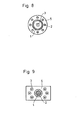
- FIG. 8 schematically shows a superconductor wire in which a multiplicity of filaments 3 made of, for example, Nb 3Al in a copper matrix is enclosed by a tube made of reinforcing material 1 (e.g. made of tantalum), around which in turn a layer made of a known stabilizing material 5, for example made of aluminum, with 8 embedded wires 2 (eg made of Cu-A1203).
- a multiplicity of filaments 3 made of, for example, Nb 3Al in a copper matrix is enclosed by a tube made of reinforcing material 1 (e.g. made of tantalum), around which in turn a layer made of a known stabilizing material 5, for example made of aluminum, with 8 embedded wires 2 (eg made of Cu-A1203).
- reinforcing material 1 e.g. made of tantalum
- FIG. 9 is a schematic illustration of the cross section of a superconductor, in the center of which there is a composite reinforcement element in the form of a wire with a core made of material 1 (for example molybdenum) and with an outer layer of material 2 (for example steel).
- a composite reinforcement element in the form of a wire with a core made of material 1 (for example molybdenum) and with an outer layer of material 2 (for example steel).
- 6 superconductor wires 3 for example, from a large number of Nb 3 Sn filaments in a bronze matrix
- a stabilizing material 4 eg made of aluminum
- Figure 10 shows schematically a cross section of a superconductor, which is constructed similarly to that in Figure 9.
- the composite reinforcing element has the shape of a band around which a larger number of superconductor wires 3, embedded in one of the thermal and electrical stabilizing material 5 (made of copper, for example).
- FIG. 11 schematically shows a cross section of a superconductor which contains a multiplicity of superconductor wires 3 / with spaces 6 through which liquid helium of approx. 4 K can flow, with a composite reinforcing element formed as a sheath from an inner layer made of material 1 and an outer layer made of material 2.
- the superconductor wires can consist of a large number of Nb 3 sn filaments in a Cu-Sn matrix, the composite reinforcement element on the inside of molybdenum and on the outside of Inconel.
- FIG. 12 is a graphic representation, the curves 7 to 11 of which show the effect of the superconductors according to the invention or of the reinforcement materials used according to the invention in high critical magnetic fields in comparison to prior art superconductors which have been reinforced exclusively with steel.
- Nb 3 Sn bronze wires with a diameter of 0.62 mm and with an internal reinforcement were used, which were subjected to a final heat treatment at 973 ° K for 64 hours .
Landscapes
- Engineering & Computer Science (AREA)
- Manufacturing & Machinery (AREA)
- Superconductors And Manufacturing Methods Therefor (AREA)
Applications Claiming Priority (2)
| Application Number | Priority Date | Filing Date | Title |
|---|---|---|---|
| DE19833329390 DE3329390A1 (de) | 1983-08-13 | 1983-08-13 | Mechanisch verstaerkte supraleiter mit verbesserten eigenschaften bei hohen magnetfeldern und verfahren zu deren herstellung |
| DE3329390 | 1983-08-13 |
Publications (3)
| Publication Number | Publication Date |
|---|---|
| EP0134902A2 true EP0134902A2 (fr) | 1985-03-27 |
| EP0134902A3 EP0134902A3 (en) | 1985-09-25 |
| EP0134902B1 EP0134902B1 (fr) | 1988-07-20 |
Family
ID=6206547
Family Applications (1)
| Application Number | Title | Priority Date | Filing Date |
|---|---|---|---|
| EP84105863A Expired EP0134902B1 (fr) | 1983-08-13 | 1984-05-23 | Supra-conducteur renforcé mécaniquement à propriétés améliorées dans des champs magnétiques élévés, et son procédé de fabrication |
Country Status (2)
| Country | Link |
|---|---|
| EP (1) | EP0134902B1 (fr) |
| DE (1) | DE3329390A1 (fr) |
Cited By (1)
| Publication number | Priority date | Publication date | Assignee | Title |
|---|---|---|---|---|
| EP0389940A3 (fr) * | 1989-03-31 | 1991-01-16 | General Electric Company | Méthode de recuit pour conducteur Nb-Sn en longueur stabilisé |
Families Citing this family (2)
| Publication number | Priority date | Publication date | Assignee | Title |
|---|---|---|---|---|
| DE3824042A1 (de) * | 1988-07-15 | 1990-01-18 | Bruker Analytische Messtechnik | Wicklungsanordnung fuer einen kryomagneten |
| DE102007018269A1 (de) | 2007-04-18 | 2008-10-30 | European Advanced Superconductors Gmbh & Co. Kg | Multifilamentsupraleiter sowie Verfahren zu dessen Herstellung |
Family Cites Families (6)
| Publication number | Priority date | Publication date | Assignee | Title |
|---|---|---|---|---|
| NL6614866A (fr) * | 1965-11-08 | 1967-05-09 | ||
| GB1206472A (en) * | 1967-05-23 | 1970-09-23 | British Insulated Callenders | Improvements in electric conductors and electric power cables incorporating them |
| FR2132994A5 (fr) * | 1971-04-05 | 1972-11-24 | Comp Generale Electricite | |
| DE2925638A1 (de) * | 1979-06-05 | 1980-12-11 | Bbc Brown Boveri & Cie | Supraleitendes kabel |
| DE3035220A1 (de) * | 1980-09-18 | 1982-04-29 | Kernforschungszentrum Karlsruhe Gmbh, 7500 Karlsruhe | Supraleitende draehte auf der basis von bronze-nb (pfeil abwaerts)3(pfeil abwaerts)sn und verfahren zu deren herstellung |
| DE3112372A1 (de) * | 1981-03-28 | 1982-10-07 | Kernforschungszentrum Karlsruhe Gmbh, 7500 Karlsruhe | Stabilisierte multifilament-supraleiter aus sproeden, vorreagierten nb(pfeil abwaerts)(pfeil abwaerts)3(pfeil abwaerts)(pfeil abwaerts)sn-filamenten in bronze-matrix |
-
1983
- 1983-08-13 DE DE19833329390 patent/DE3329390A1/de active Granted
-
1984
- 1984-05-23 EP EP84105863A patent/EP0134902B1/fr not_active Expired
Cited By (1)
| Publication number | Priority date | Publication date | Assignee | Title |
|---|---|---|---|---|
| EP0389940A3 (fr) * | 1989-03-31 | 1991-01-16 | General Electric Company | Méthode de recuit pour conducteur Nb-Sn en longueur stabilisé |
Also Published As
| Publication number | Publication date |
|---|---|
| DE3329390C2 (fr) | 1989-06-15 |
| EP0134902B1 (fr) | 1988-07-20 |
| DE3329390A1 (de) | 1985-02-21 |
| EP0134902A3 (en) | 1985-09-25 |
Similar Documents
| Publication | Publication Date | Title |
|---|---|---|
| DE69301963T2 (de) | Verfahren zur Herstellung einer Hochspannungsleitung | |
| DE3430159C2 (fr) | ||
| DE4109781A1 (de) | Supraleitfaehige litze fuer wechselstrom | |
| DE3112372C2 (fr) | ||
| DE3531769A1 (de) | Verfahren zur herstellung von multifilament-supraleiterdraehten aus nb(pfeil abwaerts)3(pfeil abwaerts)sn- oder v(pfeil abwaerts)3(pfeil abwaerts)ga-filamenten, eingebettet in einer cu- oder cu-legierungs-matrix, welche metallische zusatzelemente enthalten, mit vorbestimmten supraleitenden eigenschaften | |
| EP1983582A2 (fr) | Supraconducteur multifilaments et son procédé de fabrication | |
| DE2412573A1 (de) | Verfahren zur herstellung eines unterteilten supraleitenden drahtes | |
| DE10140109A1 (de) | Supraleitender Draht auf Nb¶3¶Sn-Basis | |
| DE3531770A1 (de) | Multifilament-supraleiterdraehte, bestehend aus mit kupfer oder mit kupfer-legierung umgebenen filamenten aus nb(pfeil abwaerts)3(pfeil abwaerts)sn oder v(pfeil abwaerts)3(pfeil abwaerts)ga mit zusaetzen sowie verfahren zu deren herstellung | |
| EP0223137B1 (fr) | Supraconducteur composite à filaments multiples et son procédé de fabrication | |
| DE69403362T2 (de) | Draht für Nb3X Supraleiterdraht | |
| DE102007018268A1 (de) | Multifilamentsupraleiter sowie Verfahren zu dessen Herstellung | |
| EP0134902B1 (fr) | Supra-conducteur renforcé mécaniquement à propriétés améliorées dans des champs magnétiques élévés, et son procédé de fabrication | |
| DE69217681T2 (de) | Supraleitender Draht mit supraleitendem Oxidwerkstoff | |
| DE7602004U1 (de) | Supraleiter | |
| DE69421197T2 (de) | Verfahren zur Herstellung eines Nb3X supraleitenden Drahtes | |
| DE4317703C2 (de) | Supraleitender Draht aus einer Nb-Ti-Legierung und ein Verfahren zu dessen Herstellung | |
| DE2826810C2 (fr) | ||
| DE3245903C2 (fr) | ||
| EP0196473B1 (fr) | Supraconducteur à armature pour champ élevé ainsi que procédé de fabrication et application de ce supraconducteur | |
| DE69120685T2 (de) | Supraleiter und herstellungsverfahren | |
| DE69608078T2 (de) | Mehradriger supraleitender Nb3Al-Draht | |
| DE602004006368T2 (de) | Nb3Sn-Supraleiterelement | |
| DE2723744C3 (de) | Volltransponierter bandförmiger Leiter | |
| DE2602729A1 (de) | Supraleiter |
Legal Events
| Date | Code | Title | Description |
|---|---|---|---|
| PUAI | Public reference made under article 153(3) epc to a published international application that has entered the european phase |
Free format text: ORIGINAL CODE: 0009012 |
|
| AK | Designated contracting states |
Designated state(s): CH GB IT LI NL |
|
| 17P | Request for examination filed |
Effective date: 19850208 |
|
| PUAL | Search report despatched |
Free format text: ORIGINAL CODE: 0009013 |
|
| AK | Designated contracting states |
Designated state(s): CH GB IT LI NL |
|
| 17Q | First examination report despatched |
Effective date: 19861118 |
|
| GRAA | (expected) grant |
Free format text: ORIGINAL CODE: 0009210 |
|
| AK | Designated contracting states |
Kind code of ref document: B1 Designated state(s): CH GB IT LI NL |
|
| ITF | It: translation for a ep patent filed | ||
| GBT | Gb: translation of ep patent filed (gb section 77(6)(a)/1977) | ||
| PLBE | No opposition filed within time limit |
Free format text: ORIGINAL CODE: 0009261 |
|
| STAA | Information on the status of an ep patent application or granted ep patent |
Free format text: STATUS: NO OPPOSITION FILED WITHIN TIME LIMIT |
|
| 26N | No opposition filed | ||
| ITTA | It: last paid annual fee | ||
| REG | Reference to a national code |
Ref country code: GB Ref legal event code: IF02 |
|
| PGFP | Annual fee paid to national office [announced via postgrant information from national office to epo] |
Ref country code: GB Payment date: 20030225 Year of fee payment: 20 |
|
| PGFP | Annual fee paid to national office [announced via postgrant information from national office to epo] |
Ref country code: CH Payment date: 20030429 Year of fee payment: 20 |
|
| PGFP | Annual fee paid to national office [announced via postgrant information from national office to epo] |
Ref country code: NL Payment date: 20030528 Year of fee payment: 20 |
|
| PG25 | Lapsed in a contracting state [announced via postgrant information from national office to epo] |
Ref country code: LI Free format text: LAPSE BECAUSE OF EXPIRATION OF PROTECTION Effective date: 20040522 Ref country code: CH Free format text: LAPSE BECAUSE OF EXPIRATION OF PROTECTION Effective date: 20040522 Ref country code: GB Free format text: LAPSE BECAUSE OF EXPIRATION OF PROTECTION Effective date: 20040522 |
|
| PG25 | Lapsed in a contracting state [announced via postgrant information from national office to epo] |
Ref country code: NL Free format text: LAPSE BECAUSE OF EXPIRATION OF PROTECTION Effective date: 20040523 |
|
| REG | Reference to a national code |
Ref country code: CH Ref legal event code: PL |
|
| REG | Reference to a national code |
Ref country code: GB Ref legal event code: PE20 |
|
| NLV7 | Nl: ceased due to reaching the maximum lifetime of a patent |
Effective date: 20040523 |