EP0134759A2 - A bellows-type shutting means that can be opened from either sides - Google Patents
A bellows-type shutting means that can be opened from either sides Download PDFInfo
- Publication number
- EP0134759A2 EP0134759A2 EP84830160A EP84830160A EP0134759A2 EP 0134759 A2 EP0134759 A2 EP 0134759A2 EP 84830160 A EP84830160 A EP 84830160A EP 84830160 A EP84830160 A EP 84830160A EP 0134759 A2 EP0134759 A2 EP 0134759A2
- Authority
- EP
- European Patent Office
- Prior art keywords
- bellows
- wings
- type shutting
- shutting means
- guides
- Prior art date
- Legal status (The legal status is an assumption and is not a legal conclusion. Google has not performed a legal analysis and makes no representation as to the accuracy of the status listed.)
- Withdrawn
Links
Images


Classifications
-
- E—FIXED CONSTRUCTIONS
- E05—LOCKS; KEYS; WINDOW OR DOOR FITTINGS; SAFES
- E05D—HINGES OR SUSPENSION DEVICES FOR DOORS, WINDOWS OR WINGS
- E05D15/00—Suspension arrangements for wings
- E05D15/26—Suspension arrangements for wings for folding wings
-
- E—FIXED CONSTRUCTIONS
- E06—DOORS, WINDOWS, SHUTTERS, OR ROLLER BLINDS IN GENERAL; LADDERS
- E06B—FIXED OR MOVABLE CLOSURES FOR OPENINGS IN BUILDINGS, VEHICLES, FENCES OR LIKE ENCLOSURES IN GENERAL, e.g. DOORS, WINDOWS, BLINDS, GATES
- E06B3/00—Window sashes, door leaves, or like elements for closing wall or like openings; Layout of fixed or moving closures, e.g. windows in wall or like openings; Features of rigidly-mounted outer frames relating to the mounting of wing frames
- E06B3/32—Arrangements of wings characterised by the manner of movement; Arrangements of movable wings in openings; Features of wings or frames relating solely to the manner of movement of the wing
- E06B3/48—Wings connected at their edges, e.g. foldable wings
- E06B3/481—Wings foldable in a zig-zag manner or bi-fold wings
- E06B3/482—Wings foldable in a zig-zag manner or bi-fold wings specially adapted for furniture
-
- E—FIXED CONSTRUCTIONS
- E05—LOCKS; KEYS; WINDOW OR DOOR FITTINGS; SAFES
- E05Y—INDEXING SCHEME RELATING TO HINGES OR OTHER SUSPENSION DEVICES FOR DOORS, WINDOWS OR WINGS AND DEVICES FOR MOVING WINGS INTO OPEN OR CLOSED POSITION, CHECKS FOR WINGS AND WING FITTINGS NOT OTHERWISE PROVIDED FOR, CONCERNED WITH THE FUNCTIONING OF THE WING
- E05Y2900/00—Application of doors, windows, wings or fittings thereof
- E05Y2900/10—Application of doors, windows, wings or fittings thereof for buildings or parts thereof
- E05Y2900/13—Application of doors, windows, wings or fittings thereof for buildings or parts thereof characterised by the type of wing
- E05Y2900/132—Doors
Definitions
- This invention proposes a bellows-type shutting means for closing the entrance to a room in dwelling-houses and the like, in which the wings, unlike prior art systems of similar type, can so translate all the way on their support guides that the passage to the room will.be cleared in a thorough manner.
- the different components can be produced to the desired size in a few'minu tes, which means that extreme flexibility and adaptation of the system to most different requirements is ensured.
- shutting systems utilize wings that can slide on runners but without folding of the wings being permitted.
- a shutting system comprises a plurality of folding wings that are mounted on guide means, the particular design of which is such that the wings can be caused to slide all the way to move them at will on the guides, thereby enabling a passage into a room to be cleared in a thorough manner.
- the wings according to the invention include, in addition, a wing frame that is stiffened by the aid of a tie element, so that any warping thereof,is prevented.
- shutting system which comprises a plurality of folding wings 1 , the top ends of which are mounted on hinge means that are designed to slide on upper and lower guide means 2 and 3 to be described later, while the ends of the wings terminate in end-elements 4.
- the wings comprise (fig. 4 ) a wing frame that is formed by stiles 5 interconnected by horizontal pieces 6 forming together a peripheral framing that is closed at the front by a panel 7.
- the bottom guide means comprises, on the other hand, a floor-fastened crosspiece or sleeper 20 having fitted there to a section bar 2 1 or the like, which is so shaped as to form both a support track 22 for the wheels 15 of the carriage 13 to run thereon, and an oppositely arranged track 22' for the running thereon of the carriage wheels 15 '.
- the bottom track is also provided with a front bumper skirt 23 carrying at its upper side antidust brushes 24.
- top and bottom guide means abut against protruding parts 25 (fig. 5) that are fitted to the side elements 4 at inward ly lying locations with respect to the edge of said elements.
- the lower carriages 13 and the upper rolls 14 are fitted by means of hinges to the bottom and top sides of each wing such that a free rotation of the two parts of the concerned wing is ensured.
- the tie means 8 are effective for supporting the weight of an outwardly project ing wing, thereby to avoid warping thereof and to have the forces more evenly distributed on the supporting hinges.
- both the sizes and the selected materials may be different, depending on the requirements that are to be met in use.
Abstract
The invention relates to a bellows-type shutting means having sliding wings, for closing the entrance to a room in dwelling-houses and the like, in which the wings (1), mounted on relevant upper and lower guides by the aid of hinges that are arranged to slide on said guides, can so translate all the way on said guides that the passage to the room will be cleared in a thorough manner.
Description
- This invention proposes a bellows-type shutting means for closing the entrance to a room in dwelling-houses and the like, in which the wings, unlike prior art systems of similar type, can so translate all the way on their support guides that the passage to the room will.be cleared in a thorough manner.
- By the particular design of the elements forming the shut ting means according to the invention, the different components can be produced to the desired size in a few'minu tes, which means that extreme flexibility and adaptation of the system to most different requirements is ensured.
- Shutting means for dwelling rooms, pieces of furniture or the like are known at present which comprise folding wings one end-side of which can slide on supporting guides or runners, while the other end-side is hinged at fixed locations to these guides.
- Other types of shutting systems utilize wings that can slide on runners but without folding of the wings being permitted.
- Both the above systems, however, have a drawback in that they do not permit a door passage to be cleared thoroughly. In the case of sliding wings, in fact, there always is a portion of the passage, corresponding to the width of at least one wing, which remains in an obstructed condition, while in the case of shutting systems comprising a plurality of folding wings - of which at least one end-side is a fixed side - the largest passage opening that is attainable will correspond to the width of one such folding elements.
- In this latter case, moreover, in particular when using wings of great size and weight, the wings tend to be warped or distorted or to cause their supporting hinges to become distorted, which will obviously result in undesirable disadvantages.
- In order to avoid the above disadvantages, a shutting system according to this invention comprises a plurality of folding wings that are mounted on guide means, the particular design of which is such that the wings can be caused to slide all the way to move them at will on the guides, thereby enabling a passage into a room to be cleared in a thorough manner.
- The wings according to the invention include, in addition, a wing frame that is stiffened by the aid of a tie element, so that any warping thereof,is prevented.
- The invention will be fully described hereinbelow with reference to the accompanying drawings, in which:
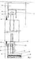
- - Figure 1 shows a sectional view of the supporting guides for the shutting wings;
- - Figures 2 and 3 are perspective views showing one of the carriages associated with the shutting wings, and said one carriage when in place on the bottom guide, respective ly;
- - Figure 4 is a rear view of a shutting wing;
- - Figure 5 shows, in a part-view, an end element of the shut ting system according to the invention;
- - Figure 6 is a detail view showing part of a wing according to the invention;
- - Figure 7 is a perspective view of a shutting system in accordance with the invention.
- Referring now to figure 7, there is shown a shutting system according to the invention, which comprises a plurality of folding wings 1, the top ends of which are mounted on hinge means that are designed to slide on upper and lower guide means 2 and 3 to be described later, while the ends of the wings terminate in end-elements 4.
- The wings comprise (fig. 4) a wing frame that is formed by stiles 5 interconnected by horizontal pieces 6 forming together a peripheral framing that is closed at the front by a panel 7.
- The bottom guide means comprises, on the other hand, a floor-fastened crosspiece or
sleeper 20 having fitted there to asection bar 21 or the like, which is so shaped as to form both asupport track 22 for thewheels 15 of thecarriage 13 to run thereon, and an oppositely arranged track 22' for the running thereon of the carriage wheels 15'. - The bottom track is also provided with a
front bumper skirt 23 carrying at its upperside antidust brushes 24. - The top and bottom guide means abut against protruding parts 25 (fig. 5) that are fitted to the side elements 4 at inward ly lying locations with respect to the edge of said elements.
- The lower carriages 13 and the upper rolls 14 are fitted by means of hinges to the bottom and top sides of each wing such that a free rotation of the two parts of the concerned wing is ensured.
- In use, when the door wings are opened, the tie means 8 are effective for supporting the weight of an outwardly project ing wing, thereby to avoid warping thereof and to have the forces more evenly distributed on the supporting hinges.
- On the other hand, the fact of providing for all of the hinge means to be slidable,lby the aid of the upper rolls 14 or the
lower carriages 13, permits to cause the wings, when opened, to slide by moving all of them to one side, thereby to clear the entire passage. - It should be apparent, moreover, that the special design of the components allow for shutting means of many different sizes to be manufactured without any difficulty; it is, in fact, sufficient to cut to the desired length the section bars that have to form the guide means and those that have to form the side shutting elements 4. Likewise, with regard to the wings, it is only necessary to vary the length of the stiles 5 and the panel 7, which can then be assembled immediately.
- Obviously, both the sizes and the selected materials may be different, depending on the requirements that are to be met in use.
Claims (7)
1. A bellows-type shutting means having sliding wings, characterized in that a plurality of folding wings (1) are mounted on a pair of guides by the aid of hinges that are arranged to slide on said guides.
2. A bellows-type shutting means having sliding wings, characterized in that the wings (1) are mounted, by means of hinges, on rolls (4 ) that can run on an upper guide, and on carriages (13') that can run on a lower guide.
3. The bellows-type shutting means according to the preceding claims, characterized in.that the carriages (13) are provided with wheels (15 and 15') having grooved profiles, said wheels being arranged in an offset relationship with one another.
4. The bellows-type shutting means according to the prece ding claims, characterized in that the lower guide is a section bar (21) that is so shaped as to form both a support ing track (22) for the wheels (15) of carriages (13) to run thereon, and an oppositely arranged track (22') for the running thereon of the carriage wheels (15').
5. The bellows-type shutting means according to claim 1, characterized in that the upper guide is a channel (17) that forms a track in which the rolls (14) can run, the rolls being mounted on a vertical axis.
6. A bellows-type shutting means having sliding wings, according to claim 1 and one or more of the preceding claims, characterized in that front bumper panels (23 and 18) are provided and serve as cover means for the lower and upper guides respectively, said cover panels (23 and 18) having antidust brushes (24 and 19) carried thereon; respectively.
7. A bellows-type shutting means having sliding wings, according to claim 1 and one or more of the preceding claims, characterized in that a diagonally arranged tie means (8) is provided inside each wing (7) and is so located as to work between the corner of the wing that is associated with the upper hinge and the lower corner opposed thereto, said tie means (8) being adjustable in tension by the aid of screw means (9).
Applications Claiming Priority (4)
| Application Number | Priority Date | Filing Date | Title |
|---|---|---|---|
| IT2291683U | 1983-09-09 | ||
| IT2291683U IT8322916V0 (en) | 1983-09-09 | 1983-09-09 | BELLOWS CLOSURE WITH SLIDING DOORS. |
| IT2367583U | 1983-11-28 | ||
| IT2367583U IT8323675V0 (en) | 1983-11-28 | 1983-11-28 | BELLOW CLOSURE, OPENABLE ON BOTH SIDES. |
Publications (2)
| Publication Number | Publication Date |
|---|---|
| EP0134759A2 true EP0134759A2 (en) | 1985-03-20 |
| EP0134759A3 EP0134759A3 (en) | 1985-08-28 |
Family
ID=26328289
Family Applications (1)
| Application Number | Title | Priority Date | Filing Date |
|---|---|---|---|
| EP84830160A Withdrawn EP0134759A3 (en) | 1983-09-09 | 1984-05-24 | A bellows-type shutting means that can be opened from either sides |
Country Status (1)
| Country | Link |
|---|---|
| EP (1) | EP0134759A3 (en) |
Cited By (4)
| Publication number | Priority date | Publication date | Assignee | Title |
|---|---|---|---|---|
| DE3720784A1 (en) * | 1987-06-24 | 1989-01-05 | Denk Fa | Sectional door |
| EP0338223A1 (en) * | 1988-04-18 | 1989-10-25 | Movi S.R.L. | A bellows-type door having sliding wings |
| EP0468223A2 (en) * | 1990-07-24 | 1992-01-29 | Karlheinz Bockisch | Folding door |
| US20110079762A1 (en) * | 2008-04-04 | 2011-04-07 | David Adderton | Barrier assembly for balconies |
Citations (7)
| Publication number | Priority date | Publication date | Assignee | Title |
|---|---|---|---|---|
| US1496904A (en) * | 1923-04-23 | 1924-06-10 | Richards Wilcox Mfg Co | Means for slidingly supporting folding doors |
| US1584664A (en) * | 1923-12-22 | 1926-05-11 | Alphonse A Sebastian | Window construction |
| GB328745A (en) * | 1929-03-21 | 1930-05-08 | Educational Supply Ass Ltd | Improvements in and relating to sliding and folding partitions, doors and windows |
| US1923961A (en) * | 1930-04-14 | 1933-08-22 | Albert E Wood | Apparatus for reenforcing doors |
| US3093424A (en) * | 1960-10-14 | 1963-06-11 | Pernetta Charles | Rectilinearly guided members |
| FR1443850A (en) * | 1965-08-21 | 1966-06-24 | Hinged and Hanging Door Closets Improvements | |
| US4133364A (en) * | 1977-12-30 | 1979-01-09 | Jay A. Smart Research, Ltd. | Diagonal bracing for lead post of folding partition |
-
1984
- 1984-05-24 EP EP84830160A patent/EP0134759A3/en not_active Withdrawn
Patent Citations (7)
| Publication number | Priority date | Publication date | Assignee | Title |
|---|---|---|---|---|
| US1496904A (en) * | 1923-04-23 | 1924-06-10 | Richards Wilcox Mfg Co | Means for slidingly supporting folding doors |
| US1584664A (en) * | 1923-12-22 | 1926-05-11 | Alphonse A Sebastian | Window construction |
| GB328745A (en) * | 1929-03-21 | 1930-05-08 | Educational Supply Ass Ltd | Improvements in and relating to sliding and folding partitions, doors and windows |
| US1923961A (en) * | 1930-04-14 | 1933-08-22 | Albert E Wood | Apparatus for reenforcing doors |
| US3093424A (en) * | 1960-10-14 | 1963-06-11 | Pernetta Charles | Rectilinearly guided members |
| FR1443850A (en) * | 1965-08-21 | 1966-06-24 | Hinged and Hanging Door Closets Improvements | |
| US4133364A (en) * | 1977-12-30 | 1979-01-09 | Jay A. Smart Research, Ltd. | Diagonal bracing for lead post of folding partition |
Cited By (5)
| Publication number | Priority date | Publication date | Assignee | Title |
|---|---|---|---|---|
| DE3720784A1 (en) * | 1987-06-24 | 1989-01-05 | Denk Fa | Sectional door |
| EP0338223A1 (en) * | 1988-04-18 | 1989-10-25 | Movi S.R.L. | A bellows-type door having sliding wings |
| EP0468223A2 (en) * | 1990-07-24 | 1992-01-29 | Karlheinz Bockisch | Folding door |
| EP0468223A3 (en) * | 1990-07-24 | 1992-04-29 | Karlheinz Bockisch | Folding door |
| US20110079762A1 (en) * | 2008-04-04 | 2011-04-07 | David Adderton | Barrier assembly for balconies |
Also Published As
| Publication number | Publication date |
|---|---|
| EP0134759A3 (en) | 1985-08-28 |
Similar Documents
| Publication | Publication Date | Title |
|---|---|---|
| US4378043A (en) | Pivoting screen panel for sectional garage door | |
| US4653566A (en) | Garage door screen system | |
| US4387760A (en) | Sliding folding door | |
| US3927709A (en) | Overhead garage door | |
| AU599328B2 (en) | An adjustable supporting structure for armored doors and an adjustable frame thereof | |
| US5522445A (en) | Accordion fold panel guide track | |
| US4532743A (en) | Sliding door assembly | |
| US3422878A (en) | Foldable door for wall openings | |
| DE3308452C2 (en) | Shower partition in the form of a flap door | |
| US5839228A (en) | Swing-up sliding door arrangement | |
| EP0134759A2 (en) | A bellows-type shutting means that can be opened from either sides | |
| US3926242A (en) | Doors | |
| US2495877A (en) | Storm sash | |
| DE7729730U1 (en) | WINDOW | |
| US2901036A (en) | Folding door assembly | |
| WO1990013725A1 (en) | Improvement in wall with a sliding door | |
| EP0370437A1 (en) | Door or window | |
| WO1996004834A1 (en) | Screen of the type having two or more overlapping sliding leaves | |
| US2900020A (en) | Telephone booth door assembly | |
| IE913549A1 (en) | A sliding entry door | |
| KR930006475Y1 (en) | Sliding shutter having opening and closing apparatus | |
| US1950012A (en) | Sliding window | |
| DE3329713A1 (en) | Folding door | |
| AU726943B3 (en) | Combination carrier and hinge for folding panels | |
| GB2243862A (en) | A gate and a guide therefore |
Legal Events
| Date | Code | Title | Description |
|---|---|---|---|
| PUAI | Public reference made under article 153(3) epc to a published international application that has entered the european phase |
Free format text: ORIGINAL CODE: 0009012 |
|
| AK | Designated contracting states |
Designated state(s): AT BE CH DE FR LI NL |
|
| PUAL | Search report despatched |
Free format text: ORIGINAL CODE: 0009013 |
|
| AK | Designated contracting states |
Designated state(s): AT BE CH DE FR LI NL |
|
| 17P | Request for examination filed |
Effective date: 19851216 |
|
| 17Q | First examination report despatched |
Effective date: 19870120 |
|
| STAA | Information on the status of an ep patent application or granted ep patent |
Free format text: STATUS: THE APPLICATION IS DEEMED TO BE WITHDRAWN |
|
| 18D | Application deemed to be withdrawn |
Effective date: 19870602 |
|
| RIN1 | Information on inventor provided before grant (corrected) |
Inventor name: VIGANO, NATALINO |